
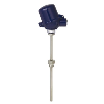
ترمومتر حراري ملولب
الوصف
تُصمَّم المزدوجات الحرارية لسلسلة الطراز هذه للتركيب اللولبي مباشرةً في العملية، بشكل أساسي في الخزانات وخطوط الأنابيب. هذه موازين الحرارة مناسبة للسوائل والغازات تحت أحمال ميكانيكية متوسطة وأحمال كيميائية عادية.
أنبوب الحماية مُلحم بالكامل ومُثبت بالبراغي في رأس التوصيل. يمكن إزالة عنصر القياس القابل للاستبدال دون إخراج مجسّ القياس بالكامل من المنشأة. يتيح ذلك إجراء الفحص أو مراقبة معدات القياس أو، عند الحاجة إلى الصيانة، إجراء الاستبدال بينما تكون المنشأة قيد التشغيل.
للموافقات الإضافية، راجع الصفحة 16
طراز TR10-C مع أنبوب حماية
يساعد اختيار الأطوال القياسية على تقصير أزمنة التسليم وعلى إمكانية تخزين قطع الغيار.
يمكن اختيار طول الإدخال، ووصل العملية، وتصميم أنبوب الحماية، ورأس التوصيل، ونوع وعدد الحساسات، ودقة القياس، كلٌّ على حدة بما يناسب التطبيق المعني. تتوفر مجموعة كبيرة من شهادات الحماية من الانفجار المختلفة الخاصة بـ TC10-C.
عند الطلب، يمكننا تركيب مرسلات تماثلية أو رقمية من نطاق WIKA في رأس التوصيل الخاص بـ TC10-C.
المزايا
- مدى المستشعر من -40 ... +1,200 °C [-40 ... +2,192 °F]
- مع أنبوب حماية مدمج
- عنصر قياس مزود بنابض ضغط (قابل للاستبدال)
- تتوفر نسخ مقاومة للانفجار لعدة أنواع من الموافقات
الأسئلة والأجوبة
ما هو نطاق القياس لهذا المزدوج الحراري؟
نطاقات الحساس تمتد من -40 °C حتى +1,200 °C حسب نوع الحساس، ونطاق درجة حرارة العملية هو -40 … +1200 °C.
ما هي دقة القياس؟
الدقة وفق Class 1 and Class 2 per IEC 60584-1، مع فئتي حساس Class 1 وClass 2.
ما هي وصلات العملية المتاحة؟
وصلات لولبية مثل G ¼ B وG ½ B وG ¾ B وG 1 B وM18 x 1.5 وM24 x 1.5 وM20 x 1.5 و½NPT و¾ NPT، بالإضافة إلى compression fitting واللحام (weld-on).
هل يمكن استخدامه في المناطق الخطرة؟
نعم، تتوفر نسخ معتمدة للحماية من الانفجار بأنواع عديدة، منها Ex i للغاز في المناطق 0 و1 و2 وللغبار في المناطق 20 و21 و22، وEx e وEx nA للغاز وEx t للغبار، بتصنيفات مثل II 1G Ex ia IIC T6...T1 Ga.
ما هي المواد المستخدمة لأنبوب الحماية؟
Alloy 600 (Inconel 600)، و316L، و1.4571، والفولاذ المقاوم للصدأ (Stainless steel).
ما هي درجة الحماية من الغبار والماء؟
درجة الحماية IP65، ونطاق درجة الحرارة المحيطة -40 … +80 °C.
ما هي إشارة الخرج وخيارات الإرسال؟
إشارة الخرج 4-20mA مع دعم HART، والتغذية loop-powered لخيارات المرسل، ويمكن عند الطلب تركيب مرسلات تماثلية أو رقمية من نطاق WIKA في رأس التوصيل.
ما الذي يميّز TC10-C عن غيره؟
عنصر القياس المثبّت بنابض قابل للاستبدال دون إخراج المجس من المنشأة، وأنبوب الحماية الملحوم بالكامل، وإمكانية اختيار طول الإدخال ووصلة العملية ونوع وعدد الحساسات كلٌّ على حدة، مع مستوى سلامة وظيفية SIL 2.
اجمع TC10-C لمهمتك
يُبنى رقم المادة تلقائيًا. عند الشك — تواصل مع مهندس؛ سنساعدك حسب معطيات الخط.
- اعتماد كهربائيWithout
- نوع الحماية من الاشتعالWithout
- المنطقةWithout
- نوع الثرمومتر الحراريType K
- عدد المزدوجات الحراريةSingle thermocouple
- فئة دقة المستشعرClass 2, IEC 60584
- حدود صلاحية دقة الفئة-40…+1200 °C
- الوصل الساخنUngrounded
- الرأس / الغطاءBSZ, Aluminum, ball shaped, flip-top
- دخول الكابلStandard cable gland for für A-/B-/J- heads
- حجم مقاس الخيط لمدخل الكابلM20 x 1.5
- مرسلWithout (terminal block)
- تفاصيل جهاز الإرسالWithout
- التوصيل بأنبوب الرقبةM24 x 1,5
- أنبوب الحمايةStraight, thread, form 2G DIN 43772
- قطر أنبوب الحماية—
- وصلة العملية—
- مادة أنبوب الحمايةStainless steel 1.4571
- طول الإدخال [A]—
- طول الرقبة [MH/N]130
- المتطلبات الميكانيكيةWithout
- تصميمات خاصة للغلاف الحراريWithout
- الشهاداتWithout
أكمل التهيئة
اختر جميع الخيارات لإرسال الطلب.
| الطراز | TC10-C |
| السلسلة | TC10 |
| النوع الفرعي | Thermocouple |
| نطاق درجة الحرارة | −40…+1200 °C · −40…+1000 °C · −40…+350 °C · −40…+750 °C · −40…+900 °C · −40…+800 °C · +0…+1260 °C · +0…+760 °C · +0…+870 °C · +0…+370 °C |
| فئة الدقة | Class 1 and Class 2 per IEC 60584-1 |
| مستوى السلامة الوظيفية (SIL) | SIL 2 |
| وصلة العملية | G ¼ BG ½ BG ¾ BG 1 BM18 x 1.5M24 x 1.5½NPTG1/2M20 x 1.51/2 NPT¾ NPTcompression fittingweld-on |
| درجة حرارة العملية | −40…+1200 °C |
| إشارة الخرج | 4-20mA · HART |
| التغذية | Loop-powered (for transmitter options) |
| وصلة كهربائية | M20 x 1.5, ½ NPT |
| مادة المجس | Alloy 600 (Inconel 600), 316L, 1.4571, Stainless steel |
| مادة جراب الحرارة | Alloy 600 (Inconel 600), 316L, 1.4571, Stainless steel |
| حرارة المحيط | −40…+80 °C |
| تصنيف IP | IP65 |
| الشهادات | CERoHSREACHEACNACENAMUR NE024 |
| حماية الانفجار | Ex i (gas) Zone 0, 1, 2Ex i (dust) Zone 20, 21, 22Ex e (gas) Zone 1, 2Ex t (dust) Zone 21, 22Ex nA (gas) Zone 2ExecIIC T1...T6GcExtbIIC T135°C DcII 1G Ex ia IIC T6...T1 GaII 2G Ex ia IIC T6...T1 GbII 1/2G Ex ia IIC T6...T1 Ga/GbII 1D Ex ia IIC T200X°C DaII 2D Ex ia IIC T200X°C DbII 1/2D Ex ia IIC TX°C Da/DbII 2G Ex eb ia IIC T6...T1 GbII 3G Ex ec ia IIC T6...T1 Gc XII 2D Ex tb IIC Tx°C DbII 3D Ex tc IIC TX°C Dc XEx ia IIC T6...T1 GaEx ia IIC T6...T1 GbEx ia IIC T6...T1 Ga/Gb0 Ex ia IIC T6...T1 Ga X1 Ex ia IIC T6...T1 Gb XEx ia IIC T65...T125°C Da XEx ib IIC T65...T125°C Db XEx ia IIC T65...T125°C Db/X2Ex ec IIC T6...T1 Gc XEx tc IIC TX°C Dc XExiaIIC T6...T3GaExiaIIC T6...T2Ga/GbExiaIIC T125...T65°C DaExiaIIC T125...T65°C Da/DbExiaIIC T1...T6GaExiaIIC T1...T6GbExiaIIC T1...T6Ga/GbExebIIC T1...T6GbExtbIIC T135°C DbExiaIIC T1~T6GaExiaIIC T1~T6GbExiaIIC T1~T6Ga/GbExiaD20T65/T95/T125ExiaD21T65/T95/T125ExiaD20/21T65/T95/T125ExiaIIC T4/T5/T6 |
| نوع المستشعر | Type K/J/E/N/T |
| فئة المستشعر | Class 1, Class 2 |
| جراب الحرارة | نعم |
| شكل جراب الحرارة | Form 2G |
| لغات ورقة البيانات | EN, DE |
| Measuring element | ||
|---|---|---|
| Type of measuring element | Thermocouple per IEC 60584-1 or ASTM E230 Types K, J, E, N,T | |
| Probe tip design (measuring location) | Ungrounded (measuring location ungrounded welded, standard) Grounded (measuring location grounded, welded to the bottom) | |
| Marking of the polarity | The colour code at the positive poles of the instrument decides the correlation of polarity and terminal | |
| Single thermocouple | ||
| Dual thermocouple | ||
| Validity limits of the class accuracy in accordance with IEC 60584-1 | ||
| Type K | Class 2 Class 1 | -40 ... +1,200 °C [-40 ... +2,192 °F] -40 ... +1,000 °C [-40 ... +1,832 °F] |
| Type J | Class 2 | -40 ...+750 °C [-40 ... +1,382 °F] |
| Type E | Class 2 Class 1 | -40 ...+900 °C [-40 ... +1,652 °F] -40 ...+800 °C [-40 ... +1,472 °F] |
| Type N | Class 2 Class 1 | -40 ... +1,200 °C [-40 ... +2,192 °F] -40 ... +1,000 °C [-40 ... +1,832 °F] |
| TypeT | Class 2 Class 1 | -40 ...+350 °C [-40 ...+662 °F] -40 ...+350 °C [-40 ...+662 °F] |
| Validity limits of the class accuracy in accordance with ASTM E230 | ||
| Type K | Standard Special | 0 ... 1,260 °C [32 ... 2,300 °F] 0 ... 1,260 °C [32 ... 2,300 °F] |
| Type J | Standard Special | 0 ... 760 °C [32 ... 1,400 °F] 0 ... 760 °C [32 ... 1,400 °F] |
| Type E | Standard | 0 ... 870 °C [32 ... 1,598 °F] |
| Special Standard | 0 ... 870 °C [32 ... 1,598 °F] 0 ... 1,260 °C [32 ... 2,300 °F] | |
| Type N | Special | 0 ... 1,260 °C [32 ... 2,300 °F] |
| TypeT | Standard Special | 0 ... 370 °C [32 ... 698 °F] 0 ... 370 °C [32 ... 698 °F] |
| Model | Material | Thread size of cable inlet | Ingress pro- tection (max.) 1) 2) IEC/EN 60529 | Cap | Surface | Connec- tion to neck tube | |
|---|---|---|---|---|---|---|---|
| BSZ, BSZ-K | BSZ | Aluminium | ■ M20 x 1.5 ■ ½NPT | IP65 | Spherical hinged cov - er with cylinder head screw | Blue, painted (RAL 5022) | M24 x 1.5 |
| BSZ-H, BSZ-HK BSZ-K | BSS Plastic | BSS-H ■ M20 x 1.5 ■ ½NPT | BVS IP65 | BVS (NuG) Spherical hinged cov - er with cylinder head screw | 1/4000 Black | 5/6000 M24 x 1.5 | |
| BSZ-H, BSZ-HK | BSZ-H | Aluminium | ■ M20 x 1.5 ■ ½NPT | IP65 | Raised hinged cover with cylinder head screw | Blue, painted (RAL 5022) | M24 x 1.5 |
| BSS BSZ-H (2 x cable outlet) | BSS-H Aluminium | BVS ■ 2 x M20 x 1.5 ■ 2x½NPT | BVS (NuG) IP65 | 5/6000 1/4000 Raised hinged cover with cylinder head screw | 7/8000 Blue, painted (RAL 5022) | 7/8000 DIH50 M24 x 1.5 | |
| BSZ-H / DIH10 3) | Aluminium | ■ M20 x 1.5 ■ ½NPT | IP65 | Raised hinged cover with cylinder head screw | Blue, painted (RAL 5022) | M24 x 1.5 | |
| BSZ-H /TND 4) | Aluminium | ■ M20 x 1.5 ■ ½NPT | IP65 | Raised hinged cover with cylinder head screw | Blue, painted (RAL 5022) | M24 x 1.5 | |
| BSZ-HK | Plastic | ■ M20 x 1.5 ■ ½NPT | IP65 | Raised hinged cover with cylinder head screw | Black | M24 x 1.5 | |
| BS | Aluminium | ■ M20 x 1.5 ■ ½NPT | IP65 | Flat cover with 2 screws | Blue, painted (RAL 5022) | M24 x 1.5 | |
| BS | BSZ, BSZ-K BSS | BSZ-H, BSZ-HK Aluminium | BSS ■ M20 x 1.5 ■ ½NPT | BSS-H IP65 | BVS Spherical hinged cover with clamping lever | BVS (NuG) Blue, painted (RAL 5022) | 1/4000 M24 x 1.5 |
| BSS | BSS-H BSS-H | BVS Aluminium | BVS (NuG) ■ M20 x 1.5 ■ ½NPT | 1/4000 IP65 | 7/8000 5/6000 Raised hinged cover with clamping lever | 7/8000 DIH50 andere Blue, painted (RAL 5022) | Anschlussgehäuse M24 x 1.5 |
| BSS-H | BVS BVS | BVS (NuG) Stainless steel | 1/4000 M20 x 1.5 | 5/6000 IP65 | 7/8000 DIH50 7/8000 Precision-cast screw- on lid | andere Anschlussgehäuse Natural finish, electropol- ished | KN4-P M24 x 1.5 |
| Model | Explosion protection | |||||
|---|---|---|---|---|---|---|
| Without | Ex i (gas) Zone 0, 1, 2 | Ex i (dust) Zone 20, 21, 22 | Ex e (gas) Zone 1, 2 | Ex t (dust) Zone 21, 22 | Ex nA (gas) Zone 2 | |
| BSZ | x | x | x | x 1) | x 1) | x 2) |
| BSZ-K | x | x | - | - | - | - |
| BSZ-H | x | x | x | x 1) | x 1) | x 2) |
| BSZ-H (2 x cable outlet) | x | x | x | x 1) | x 1) | x 2) |
| BSZ-H / DIH10 3) | x | x | - | - | - | - |
| BSZ-H /TND 4) | x | x | - | - | - | - |
| BSZ-HK | x | x | - | - | - | - |
| BS | x | x | x | - | - | - |
| Model | Explosion protection | |||||
|---|---|---|---|---|---|---|
| Without | Ex i (gas) Zone 0, 1, 2 | Ex i (dust) Zone 20, 21, 22 | Ex e (gas) Zone 1, 2 | Ex t (dust) Zone 21, 22 | Ex nA (gas) Zone 2 | |
| BSS | x | x | - | - | - | - |
| BSS-H | x | x | - | - | - | - |
| BVS | x | x | - | - | - | - |
عرض الكل (20)
| Model | Material | Thread size of cable inlet | Ingress protection (max.) 1) 2) IEC/EN 60529 | Cap | Surface | Connection to neck tube | |
|---|---|---|---|---|---|---|---|
| KN4-A | Aluminium | ■ ½NPT ■ M20 x 1.5 | IP65 | Screw-on lid | Blue, painted (RAL 5022) | M24 x 1.5 |
| Model | Explosion protection | |||||
|---|---|---|---|---|---|---|
| Without | Ex i (gas) Zone 0, 1, 2 | Ex i (dust) Zone 20, 21, 22 | Ex e (gas) Zone 1, 2 | Ex t (dust) Zone 21, 22 | Ex nA (gas) Zone 2 | |
| KN4-A | x | x | - | - | - | - |
| Cable inlet | Colour Max. ingress 1) | protection DIN EN IEC 60529 | Thread size of cable inlet | Min./Max. ambient temperature |
|---|---|---|---|---|
| Standard cable inlet 2) | Natural finish | IP65 | M20 x 1.5 | -40 ...+80 °C [-40 ...+176 °F] |
| Plastic cable gland (cable Ø6...10 mm) 2) | ■ Black ■ Grey | IP66 | ■ M20 x 1.5 ■ ½NPT | -40 ...+80 °C [-40 ...+176 °F] |
| Plastic cable gland (cable Ø 6 ... 10 mm), Ex e 2) | ■ Light blue ■ Black | IP66 | ■ M20 x 1.5 ■ ½NPT | ■ -20 ...+80 °C [-4 ...+176 °F] ■ -40 ...+70 °C [-40 ...+158 °F] |
| Nickel-plated brass cable gland (cable Ø 6 ... 12 mm) | Natural finish | IP66 | ■ M20 x 1.5 ■ ½NPT | -60 3) / -40 ...+80 °C [-76 / -40 ...+176 °F] |
| Nickel-plated brass cable gland (cable Ø 6 ... 12 mm), Ex e | Natural finish | IP66 | ■ M20 x 1.5 ■ ½NPT | -60 3) / -40 ...+80 °C [-76 / -40 ...+176 °F] |
| Stainless steel cable gland (cable Ø 7 ... 12 mm) | Natural finish | IP66 | ■ M20 x 1.5 ■ ½NPT | -60 3) / -40 ...+80 °C [-76 / -40 ...+176 °F] |
| Stainless steel cable gland (cable Ø 7 ... 12 mm), Ex e | Natural finish | IP66 | ■ M20 x 1.5 ■ ½NPT | -60 3) / -40 ...+80 °C [-76 / -40 ...+176 °F] |
| Plain threaded | - | IP00 | ■ M20 x 1.5 ■ ½NPT | - |
| 2 x plain threaded 4 ) | - | IP00 | ■ 2 x M20 x 1.5 ■ 2x½NPT | - |
| Built-in connector (male) M12 (4-pin) Built-in connector (female) M12 1 (4-pin) | - | IP65 | M20 x 1.5 | -40 ...+80 °C [-40 ...+176 °F] |
| Sealing plugs for shipping | Transparent | - | ■ M20 x 1.5 ■ ½NPT | -40 ...+80 °C [-40 ...+176 °F] |
| Cable inlet | Explosion protection | |||||
|---|---|---|---|---|---|---|
| With- out | Ex i (gas) Zone 0, 1, 2 | Ex i (dust) Zone 20, 21, 22 | Ex e (gas) Zone 1, 2 | Ex t (dust) Zone 21, 22 | Ex nA (gas) Zone 2 | |
| Standard cable inlet 1) 3) | x | x | - | - | - | - |
| Plastic cable gland 1) | x | x | - | - | - | - |
| Plastic cable gland (light blue), Ex e 1) | x | x | x | - | - | - |
| Plastic cable gland (black), Ex e 1) | x | x | x | x | x | x |
| Brass cable gland, nickel-plated | x | x | x | - | - | - |
| Brass cable gland, nickel-plated, Ex e | x | x | x | x | x | x |
| Stainless steel cable gland | x | x | x | - | - | - |
| Stainless steel cable gland, Ex e | x | x | x | x | x | x |
| Plain threaded | x | x | x 5) | x 5) | x 5) | x 5) |
| 2 x plain threaded 2) | x | x | x 5) | x 5) | x 5) | x 5) |
| Junction box M12 x 1 (4-pin) 3) | x | x 4) | x 4) | - | - | - |
| Sealing plugs for shipping | Not applicable, transport protection 5) |
| Version | Vibration-resistant mineral-insulated metal-sheathed cable (MIMS cable) | |
|---|---|---|
| Optimal heat transfer | Requirement | ■ Correct measuring insert length ■ Correct measuring insert diameter |
| Bore diameter of the protection tube | Max. 1 mm[0.039 in] larger than the measuring insert diameter | |
| Gap width | With gap widths > 0.5 mm[> 0.020 in] between protection tube and measuring insert: → Negative impact on heat transfer → Unfavourable response behaviour of the thermometer | |
| Insertion length | When fitting the measuring insert into a protection tube, it is very important to determine the correct insertion length (= protection tube length for tip thicknesses of ≤ 5.5 mm[≤ 0.217 in]). In order to ensure that the mea - suring insert is firmly pressed down onto the bottom of the protection tube, the insert must be spring-loaded (spring travel: max. 10 mm[0.394 in]). | |
| Spring travel | Max. 10 mm[0.394 in] |
| Measuring insert diameter Ø d in mm[in] | Code number per DIN 43735 | Tolerance inmm | Sheath material | |
|---|---|---|---|---|
| 3 [0.118] | Standard | 30 | 3 +0.05 -0.05 | ■ Alloy 600 (Inconel 600) ■ 316L ■ 1.4571 |
| 6 [0.236] | Standard | 60 | 6 0 -0.1 | |
| 8 [0.315] | Standard | 80 | 8 0 -0.1 | ■ Alloy 600 (Inconel 600) ■ 316L ■ 1.4571 |
| 8 [0.315] (6 [0.236] with sleeve) | Standard | - | 8 0 -0.1 | ■ Alloy 600 (Inconel 600) ■ 316L ■ 1.4571 |
| Transmitter models | Model T16 | Model T38 |
|---|---|---|
| Transmitter data sheet | TE 16.01 | TE 38.01 |
| Figure | ||
| Output signal | ||
| 4 ...20mA | x | x |
| HART ® protocol | - | x |
| Explosion protection | Ex version possible | |
| Mounting types | ||
| Mounting onto the measuring insert | With mounting on the measuring insert, the transmitter replaces the terminal block and is fixed directly to the terminal plate of the measuring insert. | |
| Mounted within the cover of the connection head | Mounting the transmitter in the cover of the connection head is preferable to mounting it on the measuring insert.With this mounting type, for one, a better thermal insulation is ensured, and in addition, exchange and mounting for servicing is simplified. |
| Possible transmitter mounting positions | Model T16 | Model T38 |
|---|---|---|
| BSZ | ○ | ○ |
| BSZ-K | ○ | ○ |
| BSZ-H | ● | ● |
| BSZ-H (2 x cable outlet) | ● | ● |
| BSZ-H / DIH10 | ○ | ○ |
| BSZ-H /TND | ○ | ○ |
| BSZ-HK | ● | ● |
| BS | ○ | - |
| BSS | ○ | ○ |
| BSS-H | ● | ● |
| BVS | ○ | ○ |
| KN4-A | ○ | ○ |
| Protection tube in accordance with DIN 43772 | Protection tube diameter | Process connection | Suitable for measuring insert diameter | Connection to head | Material 1) |
|---|---|---|---|---|---|
| Straight, form 2G, mounting thread | 9x1mm [0.35 ... 0.04 in] | G¼B,mounting thread G½B,mounting thread G¾B,mounting thread G1B, mounting thread M18 x 1.5, mounting thread M20 x 1.5, mounting thread M27 x 2, mounting thread ½NPT, mounting thread ¾NPT, mounting thread | 6 mm[0.24 in] | M24 x 1.5 (swiv - el connection, male nut) | 1.4571 |
| 11x2mm [0.43 ... 0.08 in] 12 x 2.5mm [0.47 ... 0.09 in] | G½B,mounting thread G¾B,mounting thread G1B, mounting thread M18 x 1.5, mounting thread M20 x 1.5, mounting thread M27 x 2, mounting thread ½NPT, mounting thread ¾NPT, mounting thread | 6 mm[0.24 in] | |||
| 14 x 2.5mm [0.55 ... 0.09 in] | G½B,mounting thread G¾B,mounting thread G1B, mounting thread M18 x 1.5, mounting thread M20 x 1.5, mounting thread M27 x 2, mounting thread ½NPT, mounting thread ¾NPT, mounting thread | 8 mm[0.32 in] (6 mm[0.24 in] with sleeve) | |||
| Tapered, form 3G, mounting thread | 12 x 2.5mm [0.47 ... 0.09 in], tapered to9mm [0.35 in] | G½B,mounting thread G¾B,mounting thread G1B, mounting thread M18 x 1.5, mounting thread M20 x 1.5, mounting thread M27 x 2, mounting thread ½NPT, mounting thread ¾NPT, mounting thread | 6 mm[0.24 in] | M24 x 1.5 (swiv - el connection, male nut) | 1.4571 |
| Protection tube in accordance with DIN 43772 | Protection tube diameter | Process connection | Suitable for measuring insert diameter | Connection to head | Material 1) |
|---|---|---|---|---|---|
| Straight, plain, form 2, with/without compression fitting | 9x1mm [0.35 ... 0.04 in] 11x2mm [0.43 ... 0.08 in] 12 x 2.5mm [0.47 ... 0.09 in] | G½Bcompression fitting (metal ferrule) Compression fitting½NPT (metal ferrule) Without threaded connection, plain | 6 mm[0.24 in] | M24 x 1.5 (swiv - el connection, male nut) | 1.4571 |
| Tapered, plain, form 3, with/without compression fitting | 12 x 2.5mm [0.47 ... 0.09 in], tapered to9mm [0.35 in] | G½Bcompression fitting (metal ferrule) Compression fitting½NPT (metal ferrule) Without threaded connection, plain | 6 mm[0.24 in] | M24 x 1.5 (swiv - el connection, male nut) | 1.4571 |
| Tapered protec- tion tube, not standardised | Protection tube diameter | Process connection | Suitable for measuring insert diameter | Connection to head | Material 1) |
|---|---|---|---|---|---|
| Tapered, weld- on solid tip, mounting thread | 9x1mm [0.35 ... 0.04 in], tapered to6mm [0.24 in] | G¼B,mounting thread G½B,mounting thread G¾B,mounting thread G1B, mounting thread M18 x 1.5, mounting thread M20 x 1.5, mounting thread M27 x 2, mounting thread ½NPT, mounting thread ¾NPT, mounting thread G½B,mounting thread G¾B,mounting thread | 3 mm[0.12 in] | M24 x 1.5 (swivel con - nection, male nut) | 1.4571 |
| 11x2mm [0.43 ... 0.08 in], tapered to6mm 12 x 2.5mm [0.47 ... 0.09 in], tapered to6mm [0.24 in] | G1B, mounting thread M14 x 1.5, mounting thread M18 x 1.5, mounting thread M20 x 1.5, mounting thread ½NPT, mounting thread | ||||
| Tapered, weld-on solid tip, plain, with/without compression fitting | 9x1mm [0.35 ... 0.04 in], tapered to6mm [0.24 in] 11x2mm [0.43 ... 0.08 in], tapered to6mm [0.24 in] | G½Bcompression fitting (metal ferrule) Compression fitting½NPT (metal ferrule) | |||
| 12 x 2.5mm [0.47 ... 0.09 in], taperedon6mm [0.24 in] | Without threaded connection, | ||||
| plain |
| Straight protec- tion tube, not standardised | Protection tube diameter | Process connection | Suitable for measuring insert diameter | Connection to head | Material |
|---|---|---|---|---|---|
| Straight, mounting thread | 6 mm[0.24 in] | G¼B,mounting thread G½B,mounting thread M18 x 1.5, mounting thread M20 x 1.5, mounting thread ½NPT, mounting thread | 3 mm[0.12 in] | M24 x 1.5 (swivel con - nection, male nut) | 1.4571 |
| Straight, hexagonal threaded connection, double threaded hex bushing | 9x1mm [0.35 ... 0.04 in] 12 x 2.5mm [0.47 ... 0.09 in] | G¼B,mounting thread G½B,mounting thread G¾B,mounting thread M18 x 1.5, mounting thread ½NPT, mounting thread | 6 mm[0.24 in] | M24 x 1.5 (non-rotat- able, fixed threaded connection) | 1.4571 |
| 6 mm[0.24 in] | G¼B,mounting thread G½B,mounting thread G¾B,mounting thread M18 x 1.5, mounting thread ½NPT, mounting thread | 3 mm[0.12 in] | |||
| Straight, plain, with/without compression fitting | 6x1mm [0.24 ... 0.04 in] | G½Bcompression fitting (metal ferrule) | 3 mm[0.12 in] | M24 x 1.5 (swivel con - nection, male nut) | 1.4571 |
| Compression fitting½NPT (metal ferrule) | |||||
| Without threaded connection, plain | |||||
| 9x1mm [0.35 ... 0.04 in] | G½Bcompression fitting (metal ferrule) | 6 mm[0.24 in] | 1.4571 (9 x 1 mm) | ||
| Compression fitting½NPT (metal ferrule) Without threaded connection, plain |
| Protection tube design | Standard insertion length | Min./Max. insertion length |
|---|---|---|
| Straight, mounting thread, form 2G DIN 43772 | 100, 160, 250, 400mm [3.94, 6.23, 9.84, 15.75 in] | 50 mm/ 4,000mm [1.97 in / 157.48 in] |
| Straight, hexagonal threaded connection (double threaded hex bushing) | 100, 160, 250, 400mm [3.94, 6.23, 9.84, 15.75 in] | 50 mm/ 4,000mm [1.97 in / 157.48 in] |
| Tapered, mounting thread, form 3G DIN 43772 | 160, 220, 280mm [6.23, 8.66, 11.02 in] | 110 mm/ 4,000mm [4.33 in / 157.48 in] |
| Straight, plain, with/without compression fitting, form 2 DIN 43772 | - | 50 mm/ 4,000mm [1.97 in / 157.48 in] |
| Tapered, plain, with/without compression fitting, form 3 DIN 43772 | - | 110 mm/ 4,000mm [4.33 in / 157.48 in] |
| Tapered, weld-on solid tip, mounting thread, not standardised design | 100, 160, 250, 400mm [3.94, 6.23, 9.84, 15.75 in] | 75 mm/ 4,000mm [2.95 in / 157.48 in] |
| Tapered, plain, weld-on solid tip, with/without compression fitting, not standardised design | - | 75 mm/ 4,000mm [2.95 in / 157.48 in] |
| Protection tube design | Standard neck length | Min./Max. neck length |
|---|---|---|
| Straight, mounting thread, form 2G DIN 43772 | 130 mm[5.12 in] | 30 mm/ 1,000mm [1.18 in / 39.37 in] |
| Tapered, mounting thread, form 3G DIN 43772 | 132 mm[5.19 in] | 30 mm/ 1,000mm [1.18 in / 39.37 in] |
| Straight, plain, with compression fitting, form 2 DIN 43772 | 50 mm[1.97 in] | 50 mm[1.97 in] |
| Straight, plain, without compression fitting, form 2 DIN 43772 | - | - |
| Tapered, plain, with compression fitting, form 3 DIN 43772 | 50 mm[1.97 in] | 50 mm[1.97 in] |
| Tapered, plain, without compression fitting, form 3 DIN 43772 | - | - |
| Tapered, weld-on solid tip, mounting thread, not standardised design | 130 mm[5.12 in] | 30 mm/ 1,000mm [1.18 in / 39.37 in] |
| Tapered, weld-on solid tip, with compression fitting, not standardised design | 50 mm[1.97 in] | 50 mm[1.97 in] |
| Tapered, weld-on solid tip, without process connection, not standardised design | - | - |
| Straight, hexagonal threaded connection, double threaded hex bushing | 13 mm[0.51 in] | - |
| Ambient and storage temperature | ■ -40 ...+80 °C [-40 ...+176 °F] ■ -60 1) ...+80 °C [-76 ...+176 °F] |
|---|---|
| Vibration resistance | The replaceable measuring insert is made of a MIMS cable (mineral-insulated met- al-shielded cable) that is not susceptible to vibration. Standard vibration resistance: 50 g The information on vibration resistance refers to the tip of the measuring insert. |
| First numeral | Degree of protection / Short de- scription | Test parameters |
|---|---|---|
| Degrees of protection against solid foreign bodies (defined by the 1st numeral) | ||
| 5 | Dust-protected | Per DIN EN IEC 60529 |
| 6 | Dust-tight | Per DIN EN IEC 60529 |
| Degrees of protection against water (defined by the 2nd numeral) | ||
| 4 | Protected against splash water | Per DIN EN IEC 60529 |
| 5 | Protected against water jets | Per DIN EN IEC 60529 |
| 6 | Protected against powerful water jets | Per DIN EN IEC 60529 |
لم تجد الإجابة في الوثائق؟ سيرد المهندس خلال يوم عمل.
اسأل المهندس →48 مادة قياسية من عائلة TC10
إذا كنت تعرف الرمز — اختر مباشرة. إذا لا — استخدم المُهيِّئ في الوضع «01».