
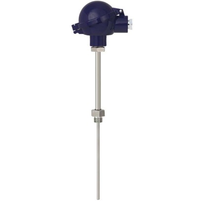
Термопара
Описание
Термопары этой серии могут быть комбинированы с большим количеством конструкций термогильз / защитных труб. Эксплуатация без термогильзы / защитной трубы рекомендуется только для некоторых применений.
Для термометров доступно большое разнообразие возможных комбинаций датчика, соединительной головки, длины погружения, длины шейки, присоединения к термогильзе / защитной трубе и т. д.; они подходят для любых размеров термогильзы / защитной трубы и для любых применений.
Для TC10-B доступно большое количество различных взрывозащищённых допусков.
По запросу мы можем установить в соединительную головку TC10-B аналоговые или цифровые преобразователи из ассортимента WIKA.
Для получения дополнительных допусков см. стр. 15
Рис. слева: модель TC10-B с соединительной головкой BSZ Рис. справа: модель TC10-B с соединительной головкой 1/4000
A
B
C
D
09
08
07
06
05
04
03
02
01
A
1
1
Особенности
- Диапазоны измерений чувствительного элемента от -40 ... +1,200 °C [-40 ... +2,192 °F]
- Со встроенной защитной гильзой из сварной трубы
- Пружинный измерительный вкладыш (сменный)
- Взрывозащищённые исполнения доступны для многих типов допусков (см. стр. 2 технической документации)
Вопросы и ответы
Какой диапазон температур измеряет термопара TC10-B?
В зависимости от типа датчика доступны диапазоны от −40 °C до +350, +750, +800, +870, +900, +1 000, +1 200 °C, а также от 0 °C до +370, +760, +870, +1 260 °C. Общий диапазон по данным производителя: −40 … +1 200 °C.
Какая точность у TC10-B?
Класс точности — по стандартам IEC 60584-1 или ASTM E230; классы датчика Class 1 и Class 2.
Можно ли использовать TC10-B во взрывоопасных зонах?
Да, доступно множество взрывозащищённых исполнений: ATEX, IECEx, EACEx, Ex Ukraine, INMETRO, CCC, NEPSI, KCs, PESO, включая Ex i (газ) для зон 0, 1, 2 и Ex i (пыль) для зон 20, 21, 22, а также исполнения Ex e, Ex t, Ex nA.
Чем TC10-B отличается от других моделей серии TC10?
TC10-B предназначена для установки в дополнительную термогильзу и имеет сменный пружинный измерительный вкладыш, что позволяет заменять датчик без демонтажа гильзы.
Какие присоединения к процессу доступны?
Резьбовые: G ¼ B, G ½ B, G ¾ B, M14 x 1.5, M18 x 1.5, M20 x 1.5, M24 x 1.5, M25, ½ NPT, ¾ NPT, 1 NPT, 1 1/2 NPT; также DIH50, KN4-A, KN4-P.
Подходит ли модель для пищевой промышленности?
Да, пищевая промышленность указана среди областей применения; доступны материалы зонда 316L и 1.4571, а также материал оболочки по заказу.
Можно ли встроить преобразователь сигнала?
Да, по запросу в соединительную головку TC10-B устанавливаются аналоговые или цифровые преобразователи WIKA; доступны выходные сигналы HART, 4 … 20 mA и PROFIBUS-PA.
Какая степень защиты корпуса?
Степень защиты IP65; температура окружающей среды при эксплуатации от −40 до +80 °C.
Соберите TC10-B под свою задачу
Артикул собирается автоматически. Если сомневаетесь — напишите инженеру; подскажем по параметрам линии.
- Стандарт взрывозащитыБез
- Маркировка взрывозащитыБез
- Маркировка взрывозащитыБез
- Градуировка термопарыТип K
- Количество измерительных спаевОдиночный спай
- Класс точности сенсораКласс 2, IEC 60584
- Рабочий диапазон термопары-40…+1200 °C
- Горячий спайНезаземленный (изолированный)
- Соединительная головка / корпусГоловка BSZ, алюминий, круглая форма, откидная крышка
- Кабельный вводСтандартный кабельный ввод для головок A-/B-/J-
- Резьба кабельного вводаM20 x 1.5
- ПреобразовательБез (с клеммным блоком)
- Информация о преобразователе0
- Присоединение к удлинительной шейкеM24 x 1,5
- Удлинительная шейкаD = 12 x 2.5 мм
- Резьба присоединения к процессуG 1/2 B
- Материал шейкиStainless steel
- Длина шейки [MH/N]150
- Глубина погружения [A]200
- Диаметр зонда—
- Материал зонда (измерительной вставки)Сплав 600
- СертификатыБез
Завершите конфигурацию
Выберите все параметры, чтобы отправить запрос.
| Модель | TC10-B |
| Серия | TC10 |
| Подтип | Thermocouple with replaceable measuring insert |
| Диапазон температуры | −40…+1200 °C · −40…+1000 °C · −40…+750 °C · −40…+350 °C · −40…+900 °C · −40…+800 °C · +0…+1260 °C · +0…+760 °C · +0…+870 °C · +0…+370 °C |
| Класс точности | Per IEC 60584-1 or ASTM E230 |
| Уровень функциональной безопасности (SIL) | SIL 2 |
| Технологическое присоединение | G ½ BG ¾ BG ¼ BM20M251/2 NPT3/4 NPT1 NPTM24 x 1.5½NPT¾NPT1 1/2 NPTDIH50KN4-AKN4-PM20 x 1.5M18 x 1.5M14 x 1.5 |
| Темп. процесса | −40…+1200 °C |
| Выходной сигнал | HART · 4-20mA · PROFIBUS-PA |
| Электр. соединение | M20 x 1.5, ½ NPT, ¾ NPT |
| Материал зонда | Alloy 600, 1.4571, 316L, MIMS, Sheath material per order |
| Темп. окружающей среды | −40…+80 °C |
| Степень защиты IP | IP65 |
| Сертификаты | RoHSCEREACHEACNAMURSIL3.12.2DAkkSATEXIECExEACExEx UkraineINMETROCCCNEPSIKCsPESO |
| Взрывозащита | Ex tb IIC TX °C DbEx tc IIC TX °C DcEx ia IIIC T1 ... T6 GaEx i (gas) Zone 0, 1, 2Ex i (dust) Zone 20, 21, 22Ex e (gas) Zone 1, 2Ex t (dust) Zone 21, 22Ex nA (gas) Zone 2ATEX Ex i (gas) Zone 0, 1, 2ATEX Ex i (dust) Zone 20, 21, 22ATEX Ex e (gas) Zone 1, 2ATEX Ex t (dust) Zone 21, 22ATEX Ex nA (gas) Zone 2IECEx Ex i (gas) Zone 0, 1, 2IECEx Ex i (dust) Zone 20, 21, 22IECEx Ex e (gas) Zone 1, 2IECEx Ex t (dust) Zone 21, 22IECEx Ex nA (gas) Zone 2EACEx Ex i (gas) Zone 0, 1, 2EACEx Ex i (dust) Zone 20, 21, 22EACEx Ex e (gas) Zone 1, 2EACEx Ex t (dust) Zone 21, 22EACEx Ex nA (gas) Zone 2Ex Ukraine Ex i (gas) Zone 0, 1, 2Ex Ukraine Ex i (dust) Zone 20, 21, 22INMETRO Ex i (gas) Zone 0, 1, 2INMETRO Ex i (dust) Zone 20, 21, 22CCC Ex i (gas) Zone 0, 1, 2CCC Ex i (dust) Zone 20, 21, 22CCC Ex e (gas) Zone 1, 2CCC Ex t (dust) Zone 21, 22NEPSI Ex i (gas) Zone 0, 1, 2NEPSI Ex i (dust) Zone 20, 21, 22KCs Ex i (gas) Zone 0, 1, 2PESO Ex i (gas) Zone 0, 1, 2II 1G Ex ia IIC T6 ... T1 GaII 2G Ex ia IIC T6 ... T1 GbII 1/2G Ex ia IIC T6 ... T1 Ga/GbII 1D Ex ia IIC T200X °C DaII 2D Ex ia IIC TX °C DbII 1/2D Ex ia IIC TX °C Da/DbII 2G Ex eb IIC T1 ... T6 GbII 3G Ex ec IIC T1 ... T6 Gc XII 2D Ex tb IIC TX °C DbII 3D Ex tc IIC TX °C Dc XEx ia IIC T6 ... T1 GaEx ia IIC T6 ... T1 GbEx ia IIC T6 ... T1 Ga/GbEx ia IIC T200X °C DaEx ia IIC TX °C DbEx ia IIC TX °C Da/DbEx eb IIC T1 ... T6 GbEx ec IIC T1 ... T6 GcEx nA IIC T1 ... T6 GcEx ia IIIC T3 ... T6 GaEx ia IIIC T3 ... T6 Ga/GbEx ia IIIC T125 ... T65 °C DaEx ia IIIC T125 ... T65 °C Da/DbEx ia IIIC T1 ... T6 GbEx ec IIIC T1 ... T6 GcEx ia IIIC T1 ~ T6 GaEx ia IIIC T1 ~ T6 GbEx ia IIIC T1 ~ T6 Ga/GbEx iaD 20 T65/T95/T125Ex ia IIIC T4/T5/T6Ex ib IIIC T4/T5/T60 Ex ia IIIC T6 ... T1 Ga X1 Ex ia IIIC T6 ... T1 Gb XEx ia IIIC T6 ... T125 °C Da XEx ib IIIC T6 ... T125 °C Db X1Ex eb IIIC T6...T1 Gb X2Ex ec IIIC T6...T1 Gc Xtb IBIIC T85 °C Db XEx tc IIIC T85 °C Dc X2Ex nA IIIC T6 ... T1 Gc XEx tb IIIC T85 °C Db X |
| Тип сенсора | Type K, Type J, Type E, Type N, Type T |
| Класс сенсора | Class 1, Class 2 |
| Диаметр зонда | 3 mm |
| Защитная гильза | Да |
| Языки datasheet | EN, DE |
| Approval | Explosion protection | ||||
|---|---|---|---|---|---|
| Ex i (gas) Zone 0, 1, 2 | Ex i (dust) Zone 20, 21, 22 | Ex e (gas) Zone 1, 2 | Ex t (dust) Zone 21, 22 | Ex nA (gas) Zone 2 | |
| ATEX | x | x | x | x | x |
| IECEx | x | x | x | x | x |
| ECASEx | - | - | x | x | x |
| EACEx | x | x | x | x | x |
| Ex Ukraine | x | x | - | - | - |
| INMETRO | x | x | - | - | - |
| CCC | x | x | x | x | - |
| NEPSI | x | x | - | - | - |
| KCs | x | - | - | - | - |
| PESO | x | - | - | - | - |
| Measuring element | |||
|---|---|---|---|
| Type of measuring element | Thermocouple per IEC 60584-1 or ASTM E230 Types K, J, E, N,T | ||
| Probe tip design (measuring location) | Ungrounded (measuring loca- tion ungrounded welded, standard) | Grounded (measuring location grounded, welded to the bottom) | |
| Thermocouple Measuring location | Thermocouple Measuring location | ||
| Sheath | |||
| Sheath | |||
| Marking of the polarity | The colour code at the positive poles of the instrument decides the correlation | ||
| Single thermocouple | of polarity and terminal | ||
| Type K | Class 2 | -40 ... +1,200 °C [-40 ... +2,192 °F] | |
| Class 1 | -40 ... +1,000 °C [-40 ... +1,832 °F] | ||
| Type J | Class 2 | ||
| -40 ...+750 °C [-40 ... +1,382 °F] | |||
| Type E | Class 2 | ||
| Class 1 | -40 ...+750 °C [-40 ... +1,382 °F] -40 ...+900 °C [-40 ... +1,652 °F] | ||
| Class 1 | -40 ...+800 °C [-40 ... +1,472 °F] | ||
| Type N | Class 2 | -40 ... +1,000 °C [-40 ... +1,832 °F] | |
| Class 1 | -40 ...+350 °C [-40 ...+662 °F] | ||
| TypeT Type K | Standard | 0 ... 1,260 °C [32 ... 2,300 °F] | |
| limits of the class accuracy in accordance | |||
| Validity | ASTM E230 | ||
| Special | |||
| 0 ... 1,260 °C [32 ... 2,300 °F] | |||
| Type J | |||
| Standard Special | 0 ... 760 °C [32 ... 1,400 °F] 0 ... 760 °C [32 ... 1,400 °F] | ||
| Type E | Standard | 0 ... 870 °C [32 ... 1,598 °F] | |
| Special | 0 ... 870 °C [32 ... 1,598 °F] | ||
| Type N | Standard | 0 ... 1,260 °C [32 ... 2,300 °F] | |
| Special | 0 ... 1,260 °C [32 ... 2,300 °F] | ||
| TypeT | Standard | 0 ... 370 °C [32 ... 698 °F] | |
| Special | 0 ... 370 °C [32 ... 698 °F] |
| Model | Material | Thread size of cable inlet | Ingress pro- tection (max.) 1) 2) IEC/EN 60529 | Cap | Surface | Connec- tion to neck tube | |
|---|---|---|---|---|---|---|---|
| BSZ, BSZ-K | BSZ | Aluminium | ■ M20 x 1.5 ■ ½NPT | IP65 | Spherical hinged cov- er with cylinder head screw | Blue, painted (RAL 5022) | ■ M24 x 1.5 ■ ½NPT |
| BSZ-H, BSZ-HK BSZ-K | BSS Plastic | BSS-H ■ M20 x 1.5 ■ ½NPT | BVS IP65 | BVS (NuG) Spherical hinged cov- er with cylinder head screw | 1/4000 Black | 5/6000 M24 x 1.5 | |
| BSZ-H, BSZ-HK | BSZ-H | Aluminium | ■ M20 x 1.5 ■ ½NPT | IP65 | Raised hinged cover with cylinder head screw | Blue, painted (RAL 5022) | ■ M24 x 1.5 ■ ½NPT |
| BSS BSZ-H (2 x cable outlet) | BSS-H Aluminium | BVS ■ 2 x M20 x 1.5 ■ 2x½NPT | BVS (NuG) IP65 | 5/6000 1/4000 Raised hinged cover with cylinder head screw | 7/8000 Blue, painted (RAL 5022) | 7/8000 DIH50 M24 x 1.5 | |
| BSZ-H / DIH10 3) | Aluminium | ■ M20 x 1.5 ■ ½NPT | IP65 | Raised hinged cover with cylinder head screw | Blue, painted (RAL 5022) | ■ M24 x 1.5 ■ ½NPT | |
| BSZ-H /TND 4) | Aluminium | ■ M20 x 1.5 ■ ½NPT | IP65 | Raised hinged cover with cylinder head screw | Blue, painted (RAL 5022) | ■ M24 x 1.5 ■ ½NPT | |
| BSZ-HK | Plastic | ■ M20 x 1.5 ■ ½NPT | IP65 | Raised hinged cover with cylinder head screw | Black | M24 x 1.5 | |
| BS | Aluminium | ■ M20 x 1.5 ■ ½NPT | IP65 | Flat cover with 2 screws | Blue, painted (RAL 5022) | ■ M24 x 1.5 ■ ½NPT | |
| BS | BSZ, BSZ-K BSS | BSZ-H, BSZ-HK Aluminium | BSS ■ M20 x 1.5 ■ ½NPT | BSS-H IP65 | BVS Spherical hinged cover with clamping lever | BVS (NuG) Blue, painted (RAL 5022) | 1/4000 ■ M24 x 1.5 ■ ½NPT |
| BSS | BSS-H BSS-H | BVS Aluminium | BVS (NuG) ■ M20 x 1.5 ■ ½NPT | 1/4000 IP65 | 7/8000 5/6000 Raised hinged cover with clamping lever | 7/8000 DIH50 andere Blue, painted (RAL 5022) | Anschlussgehäuse ■ M24 x 1.5 ■ ½NPT |
| BSS-H | BVS BVS | BVS (NuG) Stainless steel | 1/4000 M20 x 1.5 | 5/6000 IP65 | 7/8000 DIH50 7/8000 Precision-cast screw- on lid | andere Anschlussgehäuse Natural finish, electropo- lished | KN4-P M24 x 1.5 |
| Model | Explosion protection | |||||
|---|---|---|---|---|---|---|
| Without | Ex i (gas) Zone 0, 1, 2 | Ex i (dust) Zone 20, 21, 22 | Ex e (gas) Zone 1, 2 | Ex t (dust) Zone 21, 22 | Ex nA (gas) Zone 2 | |
| BSZ | x | x | x | x 1) | x 1) | x 2) |
| BSZ-K | x | x | - | - | - | - |
| BSZ-H | x | x | x | x 1) | x 1) | x 2) |
| BSZ-H (2 x cable outlet) | x | x | x | x 1) | x 1) | x 2) |
| BSZ-H / DIH10 3) | x | x | - | - | - | - |
| BSZ-H /TND 4) | x | x | - | - | - | - |
| BSZ-HK | x | x | - | - | - | - |
| BS | x | x | x | - | - | - |
Смотреть все (20)
| Model | Explosion protection | |||||
|---|---|---|---|---|---|---|
| Without | Ex i (gas) Zone 0, 1, 2 | Ex i (dust) Zone 20, 21, 22 | Ex e (gas) Zone 1, 2 | Ex t (dust) Zone 21, 22 | Ex nA (gas) Zone 2 | |
| BSS | x | x | - | - | - | - |
| BSS-H | x | x | - | - | - | - |
| BVS | x | x | - | - | - | - |
| Model | Material | Thread size of cable inlet | Ingress protection (max.) 1) 2) IEC/EN 60529 | Cap | Surface | Connection to neck tube | |
|---|---|---|---|---|---|---|---|
| KN4-P | KN4-A | Aluminium | ■ ½NPT ■ M20 x 1.5 | IP65 | Screw-on lid | Blue, painted (RAL 5022) | ■ M24 x 1.5 ■ ½NPT |
| KN4-P 3) | Polypropylene | ½NPT | IP65 | Screw-on lid | White | ½NPT | |
| 1/4000 | BVC 1/4000 | Aluminium | ■ ½NPT ■ ¾NPT ■ M20 x 1.5 | IP66 | Screw-on lid | Blue, painted (RAL 5022) | ½NPT |
| 5/6000 1/4000 | 7/8000 Stainless steel | 7/8000 DIH50 andere ■ ½NPT ■ ¾NPT ■ M20 x 1.5 | KN4-P Anschlussgehäuse IP66 | BVC Screw-on lid | Natural finish | ½NPT | |
| 7/8000 | 7/8000 | Aluminium | ■ ½NPT ■ ¾NPT ■ M20 x 1.5 | IP66 | Screw-on lid | Blue, painted (RAL 5022) | ½NPT |
| 7/8000 DIH50 7/8000 | andere Anschlussgehäuse Stainless steel | KN4-P BVC ■ ½NPT ■ ¾NPT ■ M20 x 1.5 | IP66 | Screw-on lid | Natural finish | ½NPT | |
| 7/8000 / DIH50 4) | Aluminium | ■ ½NPT ■ ¾NPT ■ M20 x 1.5 | IP66 | Screw-on lid | Blue, painted (RAL 5022) | ½NPT | |
| 7/8000 DIH50 | andere Anschlussgehäuse 7/8000 / DIH50 4) | KN4-P Stainless steel | BVC ■ ½NPT ■ ¾NPT ■ M20 x 1.5 | IP66 | Screw-on lid | Natural finish | ½NPT |
| PIH-L | Aluminium | ■ ½NPT/ closed ■ M20 x 1.5 / closed ■ 2x½NPT | IP66 | Screw-on lid, flat | Blue upper body, painted (RAL 5022) | ■ 1/2 NPT ■ M20 x 1.5 | |
| ■ 2 x M20 x 1.5 | Grey lower body, painted (RAL 7032) | ||||||
| PIH-H | Aluminium | ■ 1/2 NPT ■ M20 x 1.5 ■ 2x½NPT ■ 2 x M20 x 1.5 | IP66 | Screw-on lid, high | Blue upper body, painted (RAL 5022) | ■ 1/2 NPT ■ M20 x 1.5 | |
| Grey lower body, painted (RAL 7032) | |||||||
| PIH-W /TND 5) | Aluminium | ■ ½NPT ■ M20 x 1.5 ■ 2x½NPT ■ 2 x M20 x 1.5 | IP66 | Screw-on lid, high | Blue upper body, painted (RAL 5022) Grey lower body, painted (RAL 7032) | ■ ½NPT ■ M20 x 1.5 |
| Model | Explosion protection | |||||
|---|---|---|---|---|---|---|
| Without | Ex i (gas) Zone 0, 1, 2 | Ex i (dust) Zone 20, 21, 22 | Ex e (gas) Zone 1, 2 | Ex t (dust) Zone 21, 22 | Ex nA (gas) Zone 2 | |
| KN4-A | x | x | - | - | - | - |
| KN4-P 1) | x | - | - | - | - | - |
| 1/4000 | x | x | x | x | x | x |
| 7/8000 | x | x | x | x | x | x |
| 7/8000 / DIH50 2) | x | x | x | - | - | - |
| PIH-L / PIH-H | x | x | x | x | x | x |
| PIH-W /TND 3) | x | x | x | x | x | x |
| Cable inlet | Colour | Ingress protection (max.) IEC/EN 60529 1) | Thread size of cable inlet | Min./Max. ambi- ent temperature | |
|---|---|---|---|---|---|
| Standard cable inlet 2) Natural finish | IP65 | ■ M20 x 1.5 ■ ½NPT | -40 ...+80 °C [-40 ...+176 °F] | ||
| Plastic cable gland (cable Ø6...10 mm) 2) | ■ Black ■ Grey | IP66 | ■ M20 x 1.5 ■ ½NPT | -40 ...+80 °C [-40 ...+176 °F] | |
| Cable gland plastic (cable Ø 6 ... 10 mm), Ex e 2) | ■ Light blue ■ Black | IP66 | ■ M20 x 1.5 ■ ½NPT | ■ -20 ...+80 °C [-4 ...+176 °F] ■ -40 ...+70 °C [-40 ...+158 °F] | |
| Nickel-plated brass cable gland (cable Ø 6 ... 12 mm) | Natural finish | IP66 | ■ M20 x 1.5 ■ ½NPT | -60 3) / -40 ...+80 °C [-76 / -40 ...+176 °F] | |
| Nickel-plated brass cable gland (cable Ø6...12 mm), Ex e | Natural finish | IP66 | ■ M20 x 1.5 ■ ½NPT | -60 3) / -40 ...+80 °C [-76 / -40 ...+176 °F] | |
| Stainless steel cable gland (cable Ø 7 ... 12 mm) | Natural finish | IP66 | ■ M20 x 1.5 ■ ½NPT | -60 3) / -40 ...+80 °C [-76 / -40 ...+176 °F] | |
| Stainless steel cable gland (cable Ø 7 ... 12 mm), Ex e | Natural finish | IP66 | ■ M20 x 1.5 ■ ½NPT | -60 3) / -40 ...+80 °C [-76 / -40 ...+176 °F] | |
| Plain threaded | - | IP00 | ■ M20 x 1.5 ■ ½NPT | - | |
| 2 x plain threaded 5) | - | IP00 | ■ 2 x M20 x 1.5 ■ 2x½NPT | - | |
| Built-in connector (male) M12 x 1 (4-pin) Built-in connector (female) M12 x 1 (4-pin) | - | IP65 | M20 x 1.5 | -40 ...+80 °C [-40 ...+176 °F] | |
| Sealing plugs for shipping | Transparent | - | ■ M20 x 1.5 ■ ½NPT | -40 ...+80 °C [-40 ...+176 °F] |
| Cable inlet | Explosion protection | |||||
|---|---|---|---|---|---|---|
| With- out | Ex i (gas) Zone 0, 1, 2 | Ex i (dust) Zone 20, 21, 22 | Ex e (gas) Zone 1, 2 | Ex t (dust) Zone 21, 22 | Ex nA (gas) Zone 2 | |
| Standard cable inlet 1) 3) | x | x | - | - | - | - |
| Plastic cable gland 1) | x | x | - | - | - | - |
| Plastic cable gland (light blue), Ex e 1) | x | x | x | - | - | - |
| Plastic cable gland (black), Ex e 1) | x | x | x | x | x | x |
| Brass cable gland, nickel-plated | x | x | x | - | - | - |
| Brass cable gland, nickel-plated, Ex e | x | x | x | x | x | x |
| Stainless steel cable gland | x | x | x | - | - | - |
| Stainless steel cable gland, Ex e | x | x | x | x | x | x |
| Plain threaded | x | x | x 5) | x 5) | x 5) | x 5) |
| 2 x plain threaded 2) | x | x | x 5) | x 5) | x 5) | x 5) |
| Junction box M12 x 1 (4-pin) 3) | x | x 4) | x 4) | - | - | - |
| Sealing plugs for shipping | Not applicable, transport protection 5) |
| Versions | Vibration-resistant mineral-insulated metal-sheathed cable (MIMS cable) | |
|---|---|---|
| Optimal heat transfer | Requirement | ■ Correct measuring insert length ■ Correct measuring insert diameter |
| Bore diameter of the thermowell / protection tube | Max. 1 mm[0.039 in] larger than the measuring insert diameter | |
| Gap width | With gap widths > 0.5 mm[> 0.020 in] between thermowell / protection tube and measuring insert: →Negative impact on heat transfer →Unfavourable response behaviour of the thermometer | |
| Insertion length | When mounting the measuring insert into a thermowell, it is very important to determine the correct insertion length (= thermowell length for tip thicknesses of ≤ 5.5 mm[≤ 0.217 in]). In order to ensure that the meas - uring insert is firmly pressed down onto the bottom of the thermowell / protection tube, the insert must be spring-loaded (spring travel: max. 10 mm[0.394 in]). | |
| Spring travel | Max. 10 mm[0.394 in] |
| Measuring insert diameter Ø d in mm[in] | Code number per DIN 43735 | Tolerance inmm | Sheath material | |
|---|---|---|---|---|
| 3 [0.118] | Standard | 30 | 3 ±0.05 | ■ Alloy 600 ■ 1.4571 |
| 6 [0.236] | Standard | 60 | 6 0 -0.1 | ■ 316L |
| 8 [0.315] (6 [0.2366] with sleeve) | Standard | - | 8 0 -0.1 | ■ Alloy 600 ■ 1.4571 |
| 8 [0.315] | Standard | 80 | 8 0 -0.1 | ■ Alloy 600 ■ 1.4571 ■ 316L |
| Transmitter models | T16 | T38 |
|---|---|---|
| Transmitter data sheet | TE 16.01 | TE 38.01 |
| Figure | ||
| Output | ||
| 4 ...20mA | x | x |
| HART ® protocol | - | x |
| Input | ■ Type K ■ Type J ■ Type E ■ Type N ■ TypeT | ■ Type K ■ Type J ■ Type E ■ Type N ■ TypeT |
| Explosion protection | Ex version possible | |
| Mounting types | ||
| Mounting onto the measuring insert | With mounting on the measuring insert, the transmitter replaces the terminal block and is fixed directly to the terminal plate of the measuring insert. | |
| Mounted within the cover of the connection head | Mounting the transmitter in the cover of the connection head is preferable to mounting it on the measuring insert.With this mounting type, for one, a better thermal decoupling is ensured, and in addition, exchange and mounting for servicing is simplified. |
| Possible mounting positions for trans- mitters | Model T16 | Model T38 |
|---|---|---|
| BS | ○ | - |
| BSZ | ○ | ○ |
| BSZ-H | ● | ● |
| BSZ-H (2 x cable outlet) | ● | ● |
| BSZ-H / DIH10 | ○ | ○ |
| BSS | ○ | ○ |
| BSS-H | ● | ● |
| BVS | ○ | ○ |
| BSZ-K | ○ | ○ |
| BSZ-HK | ● | ● |
| KN4-A | ○ | ○ |
| KN4-P | ○ | ○ |
| 1/4000 | ○ | ○ |
| 7/8000 | ○ | ○ |
| 7/8000 / DIH50 | ○ | ○ |
| PIH-L / PIH-H | ○ | ○ |
| Neck tube design | Diameter | Thread to the thermowell / protection tube | Connection to head | Materials 1) |
|---|---|---|---|---|
| Neck tube per DIN 43772 | ■ 12 x 1.5mm [0.472 x 0.059 in] ■ 12 x 2.5mm [0.472 x 0.098 in] | ■ G½B ■ G¾B ■ G¼B ■ M20 x 1.5 ■ M18 x 1.5 ■ M14 x 1.5 ■ ½NPT ■ ¾NPT ■ G½Bcompression fitting (metal ferrule) ■ G¾Bcompression fitting (metal ferrule) ■ M18 x 1.5 compression fitting (metal ferrule) ■ M20 x 1.5 compression fitting (metal ferrule) ■ G½Bunion nut ■ G¾Bunion nut ■ M20 x 1.5 union nut ■ G½Bmale nut ■ G¾Bmalenut ■ M20 x 1.5 male nut ■ Without threaded connection, plain | M24 x 1.5 (swivel connection, male nut) | 1.4571 |
| Neck tube per DIN 43772 | 14 x 2.5mm [0.551 x 0.098 in] | ■ G½B ■ G¾B ■ G¼B ■ M20 x 1.5 ■ M18 x 1.5 ■ M14 x 1.5 ■ ½NPT ■ ¾NPT ■ G½Bunion nut ■ G¾Bunion nut ■ M20 x 1.5 union nut ■ G½Bmale nut ■ G¾Bmalenut | ||
| Neck tube with counter nut to head | 14 x 2.5mm [0.551 x 0.098 in] | ■ ½NPT ■ ¾NPT ■ G½B ■ G¾B ■ G¼B ■ M14 x 1.5 ■ M18 x 1.5 ■ M20 x 1.5 | M20 x 1.5 (with counter nut) | 1.4571 |
| Double threaded hex bushing (with hexagon spanner flats) | - | ■ G½B ■ G¾B ■ G¼B ■ ½NPT ■ ¾NPT ■ M14 x 1.5 ■ M18 x 1.5 ■ M20 x 1.5 | M24 x 1.5,½NPT | 1.4571 |
| 'Nipple-union-nipple' neck tube 2) | ~ 22 mm[~ 0.9 in] | ½NPT | ½NPT | 316 |
| Double threaded hex bushing (tube section) | ~ 22 mm[~ 0.9 in] | ½NPT | ½NPT | 316 |
| Neck tube design | Neck length | Min./Max. neck length |
|---|---|---|
| Neck tube per DIN 43772 | 150 mm[~ 6 in] | ■ 30 mm[~ 1.2 in] ■ 500 mm[~ 20 in] |
| Neck tube per DIN 43772, plain | 150 mm[~ 6 in] | ■ 75 mm[~ 3 in] ■ 900 mm[~ 35 in] |
| Neck tube with counter nut to head | 150 mm[~ 6 in] | ■ 75 mm[~ 3 in] ■ 250 mm[~ 10 in] |
| Double threaded hex bushing (with hexagonal spanner flats) | ||
| M24 x 1.5 to connection head, parallel thread to thermowell | 13 mm[0.512 in] | - |
| ½NPTto connection head, parallel thread to thermowell | ~ 25 mm[1 in] | - |
| M24 x 1.5 to connection head, tapered thread to thermowell | ~ 25 mm[1 in] | - |
| ½NPTto connection head, tapered thread to thermowell | ~ 25 mm[1 in] | - |
| 'Nipple-union-nipple' neck tube | ~ 150 mm[6 in] | ■ ~ 75 mm[3 in] ■ ~ 250 mm[10 in] |
| Double threaded hex bushing (tube section) | ~ 50 mm[2 in] | ■ ~ 50 mm[2 in] ■ ~ 250 mm[10 in] |
| First numeral | Degree of protection / Short description | Test parameters |
|---|---|---|
| Degrees of protection against solid foreign bodies (defined by the 1st numeral) | ||
| 5 | Dust-protected | Per IEC/EN 60529 |
| 6 | Dust-tight | Per IEC/EN 60529 |
| Degrees of protection against water (defined by the 2nd numeral) | ||
| 4 | Protected against splash water | Per IEC/EN 60529 |
| 5 | Protected against water jets | Per IEC/EN 60529 |
| 6 | Protected against powerful water jets | Per IEC/EN 60529 |
| Representation | Model | Data sheet |
|---|---|---|
| TW10 | TW95.10 | |
| TW15 | TW95.15 | |
| TW20 | TW95.20 | |
| TW25 | TW95.25 | |
| TW30 | TW95.30 | |
| TW45 | TW95.45 | |
| TW50 | TW95.50 | |
| TW55 | TW95.55 |
| Logo | Description | Country |
|---|---|---|
| EU declaration of conformity EMCDirective 1) EN 61326 emission (group 1, class A) and immunity | European Union |
| Logo | Description | Country | ||
|---|---|---|---|---|
| EU declaration of conformity | ||||
| ATEX directive Hazardous areas | European | |||
| Union | ||||
| - Ex i | Zone 0 gas | II 1G Ex ia IIC T6 ...T1 Ga | ||
| Zone 1 gas | II 2G Ex ia IIC T6 ...T1 Gb | |||
| Zone 1 mounting to zone 0 gas | II 1/2G Ex ia IIC T6 ...T1 Ga/Gb | |||
| Zone 20 dust | II 1D Ex ia IIICT 200 X °C Da | |||
| Zone 21 dust | II 2D Ex ia IIICTX °C Db | |||
| Zone 21 mounting to zone 20 dust | II 1/2D Ex ia IIICTX °C Da/Db | |||
| - Ex e 1) | Zone 1 gas | II 2G Ex eb IIC T1 ...T6 Gb 3) | ||
| Zone 2 gas | II 3G Ex ec IIC T1 ...T6 Gc X | |||
| 3) | ||||
| Zone 21 dust | II 2D Ex tb IIICTX °C Db II 3D Ex tc IIICTX °C Dc X | |||
| 1) | Zone 22 dust Zone 21 dust | II 2D Ex tb IIICTX °C Db 3) | ||
| - Ex t | Zone 22 dust | II 3D Ex tc IIICTX °C Dc X | ||
| IECEx | International | |||
| Hazardous areas | ||||
| - Ex i | Zone 0 gas | Ex ia IIC T6 ...T1 Ga | ||
| Zone 1 gas | Ex ia IIC T6 ...T1 Gb | |||
| Zone 1 mounting to zone 0 gas | Ex ia IIC T6 ...T1 Ga/Gb | |||
| Zone 20 dust | Ex ia IIICT 200 X °C Da | |||
| Zone 21 dust | II 2D Ex ia IIICTX °C Db | |||
| Zone 21 mounting to zone 20 dust | II 1/2D Ex ia IIICTX °C Da/Db | |||
| - Ex e 2) | Zone 1 gas | Ex eb IIC T1 ...T6 Gb 3) | ||
| Zone 2 gas | Ex ec IIC T1 ...T6 Gc | |||
| Zone 21 dust | Ex tb IIICTX °C Db 3) | |||
| Zone 22 dust | Ex tc IIICTX °C Dc | |||
| - Ex t 2) Zone | Zone 21 dust 22 dust | Ex tb IIICTX °C Db 3) Ex tc IIICTX °C Dc | ||
| - | ECASEx | Emirates | ||
| Hazardous areas | United Arab | |||
| - Ex e 2) | Zone 1 gas | Ex eb IIC T1 ...T6 Gb 3) | ||
| Zone 2 gas | Ex ec IIC T1 ...T6 Gc | |||
| Zone 21 dust | Ex tb IIICTX °C Db 3) | |||
| Zone 22 dust | Ex tc IIICTX °C Dc | |||
| - Ex n 2) | Zone 2 gas | Ex nA IIC T1 ...T6 Gc | ||
| - Ex t 2) | Zone 21 dust | Ex tb IIICTX °C Db 3) | ||
| Zone 22 dust | Ex tc IIICTX °C Dc | |||
| Ex Ukraine areas | Ukraine | |||
| Hazardous - Ex i | Zone 0 gas | II 1G Ex ia IIC T1 ...T6 Ga | ||
| Zone 1 gas | II 2G Ex ia IIC T1 ...T6 Gb | |||
| Zone 1 mounting to zone 0 gas | II 1/2G Ex ia IIC T1 ...T6 Ga/Gb | |||
| Zone 20 dust | II 1D Ex ia IIIC T65°C Da | |||
| Zone 21 dust | II 2D Ex ia IIIC T65°C Db | |||
| Zone 21 mounting to zone 20 dust | II 1/2D Ex ia IIIC T65°C Da/Db | |||
| Zone 2 gas | II 3G Ex ec IIC T1 ...T6 Gc | |||
| Zone 22 dust | II 3D Ex tc IIICTX °C Dc X |
| Logo Description | Country | ||
|---|---|---|---|
| INMETRO | Brazil | ||
| Zone 21 mounting to zone 20 dust Ex ia IIIC T125 ...T65 °C Da/Db CCC 3) Hazardous areas | China | ||
| NEPSI 4) Hazardous areas | China | ||
| KCs Hazardous areas | South Korea | ||
| - | PESO Hazardous areas | India | |
| EACEx Hazardous areas | Eurasian Economic Community | ||
| Zone Zone - Ex e 2) Zone Zone Zone Zone - Ex n 2) Zone 2 gas 2Ex nA IIC T6 ...T1 Gc X - Ex t 2) Zone 21 dust Ex tb IIIC T85 °C Db X 3) Zone 22 dust Ex tc IIIC T85 °C Dc X | Ukraine | ||
| - | PAC Ukraine Metrology, measurement technology | ||
| PAC Kazakhstan Metrology, measurement technology | Kazakhstan | ||
| - | MchS Permission for | Kazakhstan | |
| PAC Uzbekistan Metrology, measurement technology | Uzbekistan |
Не нашли ответа в документации? Инженер ответит в течение рабочего дня.
Спросить инженера →3 стандартных артикулов семейства TC10
Если знаете код — выберите напрямую. Если нет — пользуйтесь конфигуратором в режиме «01».