
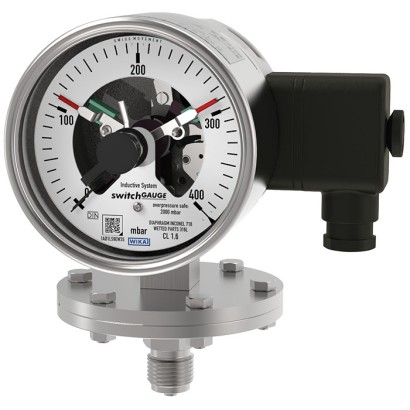
Диафрагменный манометр с контактами переключателя
Описание
Везде, где технологическое давление должно индицироваться на месте и при этом требуется переключение цепей, применяется модель PGS43 switchGAUGE.
Контакты переключателя (электрические контакты переключателя) замыкают или размыкают электрическую цепь управления в зависимости от положения стрелки показывающего измерительного прибора. Контакты переключателя регулируются по всей шкале (см. DIN 16085) и устанавливаются преимущественно под циферблатом, хотя частично — и на верхней стороне циферблата. Стрелка прибора (стрелка фактического значения) перемещается свободно по всей шкале, независимо от заданной установки.
Заданная стрелка может быть отрегулирована с помощью съемного регулировочного ключа в окне.
Особенности
- Высокая надёжность и длительный срок службы
- Широкий выбор специальных материалов
- До 4 переключающих контактов на прибор
- Также доступна с жидкостным заполнением для высоких динамических нагрузок по давлению или вибраций
- Приборы с индуктивными контактами для применения во взрывоопасных зонах
- Приборы с контактами для применений в ПЛК
Вопросы и ответы
Какой класс точности у прибора?
Класс точности 1.6 согласно EN 837-3.
Какие диапазоны измерения доступны?
От 0 … 25 мбар до 0 … 1000 мбар, от 0 … 0,6 бар до 0 … 25 бар, вакуумметрические и мановакуумметрические диапазоны (например, −1 … 24 бар), а также шкалы в psi и inHg.
Какую перегрузку выдерживает манометр?
До 10-кратного значения полной шкалы, максимум 40 бар.
Какие варианты присоединения к процессу есть?
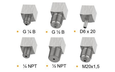
Резьба M20 x 1.5, G 1/2 B, 1/2 NPT, а также открытые присоединительные фланцы 1" class 150 RF, 2" class 150 RF, 1" class 300 RF, DN 25 PN 40 и DN 50 PN 40.
Из каких материалов могут быть изготовлены смачиваемые части?
Нержавеющая сталь 316L, сплав NiCr (Inconel), PTFE, Hastelloy, Monel, тантал и золото — что позволяет применять прибор для агрессивных, высоковязких и загрязнённых сред.
Подходит ли прибор для взрывоопасных зон?
Да, доступны исполнения с индуктивными контактами со взрывозащитой ATEX/IECEx: газ II 2G Ex ia IIC T6/T5/T4 Gb, пыль II 2D Ex ia IIIB T135°C Db, а также одобрения EAC, NEPSI и ряда других стран.
Какая степень защиты корпуса?
IP65.
Сколько контактов можно установить и какие функции они выполняют?
До 4 переключающих контактов на один прибор; доступны функции «нормально открытый», «нормально закрытый» и «переключающий».
Соберите PGS43.1X0 под свою задачу
Артикул собирается автоматически. Если сомневаетесь — напишите инженеру; подскажем по параметрам линии.
- Номинальный размер100
- Переключательконтакт с магнитным поджатием, тип 821
- Действие первого контактазамыкающий (1)
- Действие второго контактабез
- ВзрывозащитаБез
- Электрическое присоединениеразъём сбоку
- Конструкция контактовБез
- Единицы шкалымбар
- Диапазон шкалы—
- Единицы 2-й шкалы или спец. шкалыбез
- Допустимая перегрузка5 х верхний предел измерений, макс. 40 бар
- Присоединение к процессу—
- Материал мембранной пружинынержавеющая сталь
- Материал нижней части мембраныНержавеющая сталь
- Расположение присоединениярадиальное
- Гидрозаполнение корпуса—
- Корпус—
- Дроссельбез
- Особенности конструкциибез
Завершите конфигурацию
Выберите все параметры, чтобы отправить запрос.
| Модель | PGS43.100 |
| Серия | PGS43 |
| Подтип | Diaphragm pressure gauge with switch contacts |
| Диапазон давления | 0…25 mbar · 0…40 mbar · 0…60 mbar · 0…100 mbar · 0…160 mbar · 0…250 mbar · 0…400 mbar · 0…600 mbar · 0…1000 mbar · 0…0.6 bar · 0…1 bar · 0…1.6 bar · 0…2.5 bar · 0…4 bar · 0…6 bar · 0…10 bar · 0…16 bar · 0…25 bar · -0.6…0 bar · -1…0 bar · -1…0.6 bar · -1…1 bar · -1…1.5 bar · -1…2 bar · -1…3 bar · -1…5 bar · -1…9 bar · -1…10 bar · -1…15 bar · -1…24 bar · 0…10 psi · 0…15 psi · 0…30 psi · 0…60 psi · 0…100 psi · 0…150 psi · 0…160 psi · 0…200 psi · 0…250 psi · 0…300 psi · 0…400 psi · -25…0 mbar · -40…0 mbar · -60…0 mbar · -100…0 mbar · -160…0 mbar · -250…0 mbar · -400…0 mbar · -600…0 mbar · -1000…0 mbar · -5…20 mbar · -10…15 mbar · -15…25 mbar · -20…40 mbar · -30…30 mbar · -40…60 mbar · -50…200 mbar · -60…100 mbar · -100…150 mbar · -125…125 mbar · -150…250 mbar · -250…750 mbar · -400…600 mbar · -500…500 mbar · -600…400 mbar · -750…250 mbar · -800…200 mbar · -30…15 inHg · -30…60 inHg · -30…100 inHg · -30…160 inHg · -30…200 inHg · -30…300 inHg · -15…0 inHg · -30…0 inHg |
| Класс точности | 1.6 |
| Стандарт точности | EN 837-3 |
| Технологическое присоединение | M20 x 1.5Open connecting flange 1" class 150, RFOpen connecting flange 2" class 150, RFOpen connecting flange 1" class 300, RFOpen connecting flange DN 25 PN 40Open connecting flange DN 50 PN 40G ½ B½ NPTG 1/2 B1/2 NPT |
| Темп. процесса | −20…+100 °C |
| Выходной сигнал | Magnetic snap-action contact · Inductive contact · Electronic contact · Reed switch |
| Электр. соединение | Cable socket M20x1.5 |
| Функция переключения | Normally open, Normally closed, Change-over |
| Переключающие контакты | 4 |
| Материал корпуса | Stainless steel 1.4301 (304), Stainless steel 1.4571 (316 Ti) |
| Материал смачиваемых частей | Stainless steel 316L, NiCr alloy (Inconel), PTFE, Hastelloy, Monel, Tantalum, Gold |
| Материал уплотнения | FPM/FKM |
| Темп. окружающей среды | −20…+70 °C |
| Степень защиты IP | IP65 |
| Сертификаты | CERoHSCRNEN 837-3DIN 16085 |
| Взрывозащита | II 2G Ex ia IIC T6/T5/T4 GbII 2D Ex ia IIIB T135°C DbEx ia IIC T6/T5/T4 GbEx ia IIIB T135°C DbATEX directive: Gas II 2G Ex ia IIC T6/T5/T4 Gb, Dust II 2D Ex ia IIIB T135℃ DbIECEx: Gas Ex ia IIC T6/T5/T4 Gb, Dust Ex ia IIIB T135℃ DbEACEx UkraineNEPSIPAC KazakhstanMChSPAC UkrainePAC Uzbekistan |
| Диаметр шкалы | 100 mm |
| Языки datasheet | EN |
| Scale range | Overload safety 1) | Vacuum-resist- ant to -1 bar |
|---|---|---|
| mbar | ||
| 0 ... 25 | ■ 125 ■ 250 | Selectable |
| 0 ... 40 | ■ 200 ■ 400 | Selectable |
| 0 ... 60 | ■ 300 ■ 600 | Selectable |
| 0 ... 100 | ■ 500 ■ 1,000 | Selectable |
| 0 ... 160 | ■ 800 ■ 1,600 | Selectable |
| 0 ... 250 | ■ 1,250 ■ 2,500 | Selectable |
| 0 ... 400 | ■ 2,000 ■ 4,000 | Selectable |
| 0 ... 600 | ■ 3,000 ■ 6,000 | Selectable |
| 0 ... 1,000 | ■ 5,000 ■ 10,000 | Selectable |
| bar | ||
| 0 ... 0.6 | ■ 3 ■ 6 | Selectable |
| 0 ... 1 | ■ 5 ■ 10 | Selectable |
| 0 ... 1.6 | ■ 8 ■ 16 | Selectable |
| 0 ... 2.5 | ■ 12.5 ■ 25 | Selectable |
| 0 ... 4 | ■ 20 ■ 40 | Yes |
| 0 ... 6 | ■ 30 ■ 40 | Yes |
| 0 ... 10 | 40 | Yes |
| 0 ... 16 | 40 | Yes |
| 0 ... 25 | 40 | Yes |
| mbar | bar |
|---|---|
| -25 ... 0 | -0.6 ... 0 |
| -40 ... 0 | -1 ... 0 |
| -60 ... 0 | psi |
| -100 ... 0 | -15 inHg ... 0 |
| -160 ... 0 | -30 inHg ... 0 |
| -250 ... 0 | |
| -400 ... 0 | |
| -600 ... 0 | |
| -1,000 ... 0 |
| Scale range | Overload safety 1) | Vacuum-resist- ant to -1 bar | |
|---|---|---|---|
| psi | |||
| 0 ... 10 | ■ 50 ■ 100 | Selectable | |
| 0 ... 15 | ■ 75 ■ 150 | Selectable | |
| 0 ... 30 | ■ 150 ■ 300 | Selectable | |
| 0 ... 60 | ■ 300 ■ 600 | Yes | |
| 0 ... 100 | ■ 500 ■ 1,000 | Yes | |
| 0 ... 150 | ■ 750 ■ 1,500 | Yes | |
| 0 ... 160 | ■ 800 ■ 1,600 | Yes | |
| 0 ... 200 | ■ 1,000 ■ 2,000 | Yes | |
| 0 ... 250 | ■ 1,250 ■ 2,500 | Yes | |
| 0 ... 300 | ■ 1,500 ■ 3,000 | Yes | |
| 0 ... 400 | ■ 2,000 ■ 4,000 | Yes | |
| +/- scale ranges 2) | |||
| Scale range | |||
| mbar | bar | ||
| -5 ...+20 | -1 ... +0.6 | ||
| -10 ...+15 | -1 ...+1 | ||
| -15 ...+25 | -1 ... +1.5 | ||
| -20 ...+40 | -1 ...+2 | ||
| -30 ...+30 | -1 ...+3 | ||
| -40 ...+60 | -1 ...+5 | ||
| -50 ...+200 | -1 ...+9 | ||
| -60 ...+100 | -1 ...+10 | ||
| -100 ...+150 | -1 ...+15 | ||
| -125 ...+125 | -1 ...+24 | ||
| -150 ...+250 | psi | ||
| -250 ...+750 | -30 inHg ...+15 | ||
| -400 ...+600 | -30 inHg ...+60 | ||
| -500 ...+500 | -30 inHg ...+100 | ||
| -600 ...+400 | -30 inHg ...+160 | ||
| -750 ...+250 | -30 inHg ...+200 | ||
| -800 ...+200 | -30 inHg ...+300 |
| Unit | ■ bar ■ psi ■ mbar ■ kg/cm² ■ MPa ■ kPa |
|---|---|
| Other units on request | |
| Overload safety | ■ 5 x full scale value, max. 40 bar ■ 10 x full scale value, max. 40 bar |
| Vacuum resistance | ■ Without ■ Vacuum-resistant to -1 bar |
| Dial | |
| Scale layout | ■ Single scale ■ Dual scale |
| Scale colour | Single scale Black |
| Dual scale Black/Red | |
| Material | Aluminium |
| Customer-specific version | Other scales, e.g. with red mark, circular arcs or circular sectors, on request →Alternatively, adhesive label set for red and green circular arcs; see data sheet AC08.03 |
| Instrument pointer | Aluminium, black |
| Set pointer | Aluminium, red |
Смотреть все (20)
| Process connection | |
|---|---|
| Standard | ■ EN 837 ■ ANSI / ASME B1.20.1 ■ ASME B16.5 ■ EN 1092-1, form B |
| Size 1) | |
| EN 837 | ■ G½B ■ M20 x 1.5 |
| ANSI / ASME B1.20.1 | ■ ½NPT |
| ASME B16.5 | ■ Open connecting flange 1" class 150, RF ■ Open connecting flange 2" class 150, RF ■ Open connecting flange 1" class 300, RF |
| EN 1092-1, form B | ■ Open connecting flange DN 25 PN 40 ■ Open connecting flange DN 50 PN 40 |
| Materials (wetted) | |
| Diaphragm element | ■ Stainless steel 316L, for span ≤ 0.25 bar ■ NiCr alloy (Inconel), for span > 0.25 bar |
| Process connection with lower measuring flange | Stainless steel 316L |
| Coating / Lining 2) 3) | ■ Without ■ PTFE ■ Hastelloy ■ Monel ■ Tantalum ■ Gold (only for diaphragm element) |
| Other materials on request | |
| Seal 4) | FPM/FKM |
| Output signal | |
|---|---|
| Type of contact | ■ Magnetic snap-action contact, model 821 (→ See page 7) ■ Inductive contact, model 831 (→ See page 8) ■ Electronic contact, model 830 E (→ See page 9) ■ Reed switch, model 851 (→ See page 10) |
| Switching technology | |
| Magnetic snap-action contact, model 821 | ■ No control unit and no supply voltage required ■ Direct switching up to 250 V, 1 A |
| Inductive contact, model 831 | ■ Suitable for use in hazardous areas with corresponding control unit (model 904.xx) ■ Long service life due to non-contact sensor ■ Low influence on the indication accuracy ■ Fail-safe switching at high switching frequency ■ Insensitive to corrosion ■ Also available in safety version |
| Electronic contact, model 830 E | ■ For direct triggering of a programmable logic controller (PLC) ■ Long service life due to non-contact sensor ■ Low influence on the indication accuracy ■ Fail-safe switching at high switching frequency ■ Insensitive to corrosion |
| Reed switch, model 851 | ■ No control unit and no supply voltage required ■ Direct switching up to 250 V, 1 A ■ For direct triggering of a programmable logic controller (PLC) ■ Free from wear as without contact |
| Contact setting | ■ Contact(s) adjustable, adjustment key attached to cable socket ■ Contact(s) fixed, without adjustment lock 1) ■ Adjustment lock sealable (tamper-proof) ■ Adjustment lock sealed (tamper-proof) 1) ■ Captive adjustment key with the adjustment lock connected |
| Type of contact | Magnetic snap-action contact |
|---|---|
| Switching technology | ■ No control unit and no supply voltage required ■ Direct switching up to 250 V, 1 A |
| Number of switch contacts | |
| Span ≥ 25 mbar ...< 40 mbar 1) | Max. 2 switch contacts |
| Span ≥ 40 mbar | Max. 4 switch contacts |
| Switching function | ■ Separate circuits with ≥ 2 switches ■ Cable break monitoring with parallel resistance (47 kΩ or 100 kΩ) |
| The switching function of each switch is indicated by index 1, 2 or 3 | |
| Model 821.1 | Normally open (clockwise pointer motion) |
| Model 821.2 | Normally closed (clockwise pointer motion) |
| Model 821.3 | Change-over; one contact breaks and one contact makes simultaneously when pointer reaches set point |
| Switch point setting | Set pointers of the contact pressure gauges are freely adjustable over the full scale range |
| Setting range (recommended) | 25 ... 75 %of span (0 ... 100 %onrequest) |
| Distance between switch points | Recommended minimum distance between 2 contacts: 20 %of span |
| Switch hysteresis | 2 ... 5 %(typical) |
| Switching current | 0.02 ... 0.3 A (resistive load) Permissible switch-on and switch-off current: ≤ 0.5 A |
| Switching voltage | AC/DC 24 ...250V |
| Switching power 2) | |
| Unfilled instruments | ≤ 30 W, ≤ 50VA |
| Filled instruments | ≤ 20 W, ≤ 20VA |
| Contact material | Silver-nickel, gold-plated |
| Switching voltage | Unfilled instruments | Filled instruments | ||||
|---|---|---|---|---|---|---|
| Resistive load | Inductive load | Resistive load | Inductive load | |||
| Direct current | Alternating current | cos ϕ>0.7 | Direct current | Alternating current | cos ϕ>0.7 | |
| DC 220 V / AC 230 V | 100mA | 120mA | 65mA | 65mA | 90mA | 40mA |
| DC 110 V / AC 110 V | 200mA | 240mA | 130mA | 130mA | 180mA | 85mA |
| DC 48 V / AC 48 V | 300mA | 450mA | 200mA | 190mA | 330mA | 130mA |
| DC 24 V / AC 24 V | 400mA | 600mA | 250mA | 250mA | 450mA | 150mA |
| Type of contact | Inductive contact |
|---|---|
| Switching technology | ■ Suitable for use in hazardous areas with corresponding control unit (model 904.xx) ■ Long service life due to non-contact sensor ■ Low influence on the indication accuracy ■ Fail-safe switching at high switching frequency ■ Insensitive to corrosion ■ Also available in safety version |
| Number of switch contacts | |
| Span ≥ 25 mbar 1) | Max. 3 switch contacts |
| Switching function | Contact versions: ■ 831-N ■ 831-SN, safety version 2) ■ 831-S1N, safety version 2) , inverted signal The switching function of each switch is indicated by index 1 or 2 |
| Model 831.1 | Normally open (clockwise pointer motion) |
| Model 831.2 | Normally closed (clockwise pointer motion) |
| Switch point setting | Set pointers of the contact pressure gauges are freely adjustable over the full scale range |
| Setting range (recommended) | 10 ... 90 %of span (0 ... 100 %onrequest) |
| Distance between switch points | Up to 2 contacts can be set to an identical set point. For a version with 3 contacts this is not possible.The left (no. 1) or right (no. 3) contact may not be set to the same set point as the other 2 contacts.The required displacement is approx. 30°, optionally to the right or to the left. |
| Switching current | Depending on the control unit used (→ See data sheet AC 08.04) |
| Switching voltage | Depending on the control unit used (→ See data sheet AC 08.04) |
| Switching power | Depending on the control unit used (→ See data sheet AC 08.04) |
| Permissible temperature ranges in hazardous areas | |
| T6 | -20 ...+60 °C |
| T5 ...T1 | -20 ...+70 °C |
| T135°C | -20 ...+70 °C |
| Model | Version | Ex version |
|---|---|---|
| 904.28 KFA6 - SR2 - Ex1.W | 1 contact | Yes |
| 904.29 KFA6 - SR2 - Ex2.W | 2 contacts | Yes |
| 904.30 KHA6 - SH - Ex1 | 1 contact | Yes - Safety version |
| 904.33 KFD2 - SH - Ex1 | 1 contact | Yes - Safety version |
| 904.25 MSR 010-I | 1 contact | No |
| 904.26 MSR 020-I | 2 contacts | No |
| 904.27 MSR 011-I | Two-point control | No |
| Type of contact | Electronic contact (PNP transistor) |
|---|---|
| Switching technology | ■ For direct triggering of a programmable logic controller (PLC) ■ Long service life due to non-contact sensor ■ Low influence on the indication accuracy ■ Fail-safe switching at high switching frequency ■ Insensitive to corrosion |
| Number of switch contacts | |
| Span ≥ 25 mbar 1) | Max. 3 switch contacts |
| Switching function | Contact versions: ■ 2-wire system ■ 3-wire system |
| The switching function of each switch is indicated by index 1 or 2 | |
| Model 830 E.1 | Normally open (clockwise pointer motion) |
| Model 830 E.2 | Normally closed (clockwise pointer motion) |
| Setting range (recommended) | 10 ... 90 %of span (0 ... 100 %onrequest) |
| Distance between switch points | Up to 2 contacts can be set to an identical set point. For a version with 3 contacts this is not possible.The left (no. 1) or right (no. 3) contact may not be set to the same set point as the other 2 contacts.The required displacement is approx. 30°, optionally to the right or to the left. |
| Switching current | ≤ 100mA |
| Switching voltage | DC 10 ...30V |
| Type of contact 1) 2) | Bistable reed switch |
|---|---|
| Switching technology | ■ No control unit and no supply voltage required ■ Direct switching up to 250 V, 1 A ■ For direct triggering of a programmable logic controller (PLC) ■ Free from wear as without contact |
| Number of switch contacts | |
| NS 100 [4"] | Max. 2 switch contacts |
| NS 160 [6"] 3) | 1 switch contact |
| Switching function | ■ Separate circuits with ≥ 2 switches ■ Cable break monitoring with parallel resistance (47 kΩ or 100 kΩ) |
| The switching function of each switch is indicated by index 1, 2 or 3 | |
| Model 851.1 | Normally open (clockwise pointer motion) |
| Model 851.2 | Normally closed (clockwise pointer motion) |
| Model 851.3 | Change-over; one contact breaks and one contact makes simultaneously when pointer reaches set point |
| Switch point setting | Set pointers of the contact pressure gauges are freely adjustable over the full scale range |
| Setting range (recommended) | 10 ... 90 %of span |
| Distance between switch points | When using two contacts, these cannot be set to the same point. Depending on the switch- ing function, a minimum clearance of 15 ... 30° is required. |
| Switch hysteresis | 3 ...5% |
| Switching current | ≤ AC/DC 1 A |
| Switching voltage | ≤ AC/DC 250V |
| Switching power | ≤ 60 W, 60VA |
| Contact material | Rhodium |
| Transport current | AC/DC 2 A |
| Inductive load cosϕ | 1 |
| Contact resistance (static) | 100mΩ |
| Insulation resistance | 109Ω |
| Breakdown voltage | DC 1,000V |
| Switching time incl. contact chatter | 4.5 ms |
| Connection type | ■ Cable socket, black PerVDE 0110 insulation group C/250V Cable gland M20 x 1.5 ■ Connector (instead of cable socket) |
|---|---|
| Wire cross-section | 6 screw terminals + PE for 2.5 mm² |
| Cable diameter | →See dimensions |
| Pin assignment | Connection details are given on the product label of the instrument. Connection termi- nals and ground terminals are appropriately marked. |
| Material | PA 6 (polyamide) |
| Medium temperature range | ■ +100 °C [+212 °F] maximum ■ +200 °C [+392 °F] maximum |
|---|---|
| Ambient temperature range | -20 ...+60 °C [-4 ... 140 °F] |
| Storage temperature range | -20 ...+60 °C [-4 ... 140 °F] |
| Pressure limitation | |
| Steady | Full scale value |
| Fluctuating | 0.9 x full scale value |
| Ingress protection per IEC/EN 60529 | ■ IP54 ■ IP65 1) ■ IP66 2) (ingress protection of the case) |
| Logo | Description | Region |
|---|---|---|
| EU | declaration of conformity | European Union |
| EMCdirective | ||
| Low voltage directive | directive | |
| RoHS - | CRN Safety (e.g. electr. safety, overpressure, ...) | Canada |
| Logo | Description | Region |
|---|---|---|
| EU declaration of conformity | European Union | |
| ATEX directive 1) Hazardous areas IECEx 1) | International | |
| EAC EMCdirective | Eurasian Economic Community | |
| Ex Ukraine Hazardous areas 1) | Ukraine | |
| NEPSI Hazardous areas 1) | China | |
| PAC Kazakhstan Metrology, measurement technology | Kazakhstan | |
| - | MChS Permission for commissioning | Kazakhstan |
| PAC Ukraine Metrology, measurement technology | Ukraine | |
| PAC Uzbekistan Metrology, measurement technology | Uzbekistan |
| Certificates | ■ 2.2 test report per EN 10204 (e.g. state-of-the-art manufacturing, indication accuracy) ■ 3.1 inspection certificate per EN 10204 (e.g. indication accuracy) |
|---|---|
| Recommended calibration interval | 1 year (dependent on conditions of use) |
| Process connection G | Scale range | Dimensions inmm | ||||||
|---|---|---|---|---|---|---|---|---|
| Ø d | h | S2 | S3 | S4 | S5 | S6 | ||
| G½B | ≤ 250 mbar | 160 | 119 | Ø6 | 20 | 3 | 17 | Ø17.5 |
| G½B | > 250 mbar | 100 | 117 | Ø6 | 20 | 3 | 17 | Ø17.5 |
| ½NPT | ≤ 250 mbar | 160 | 118 | - | 19 | - | - | - |
| ½NPT | > 250 mbar | 100 | 116 | - | 19 | - | - | - |
| Type of contact | Dimensions inmm | |
|---|---|---|
| X | Y | |
| Single or double contact | 88 | 55 |
| Double (change-over) contact | 113 | 80 |
| Triple contact | 96 | 63 |
| Quadruple contact | 113 | 80 |
| Process connection G | Scale range | Dimensions inmm | ||||||
|---|---|---|---|---|---|---|---|---|
| Ø d | h | S2 | S3 | S4 | S5 | S6 | ||
| G½B | ≤ 250 mbar | 160 | 119 | Ø6 | 20 | 3 | 17 | Ø17.5 |
| G½B | > 250 mbar | 100 | 117 | Ø6 | 20 | 3 | 17 | Ø17.5 |
| ½NPT | ≤ 250 mbar | 160 | 118 | - | 19 | - | - | - |
| ½NPT | > 250 mbar | 100 | 116 | - | 19 | - | - | - |
Не нашли ответа в документации? Инженер ответит в течение рабочего дня.
Спросить инженера →149 стандартных артикулов семейства PGS43
Если знаете код — выберите напрямую. Если нет — пользуйтесь конфигуратором в режиме «01».