
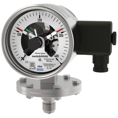
מד לחץ דיאפרגמה עם מגעי מתג
תיאור
בכל מקום שבו יש צורך להציג מקומית את לחץ התהליך, ובו-בזמן נדרשת החלפה של מעגלים, דגם PGS43 switchGAUGE מוצא את ייעודו.
מגעי מתג (מגעי מתג חשמליים) יוצרים או מנתקים מעגל בקרה חשמלי בהתאם למיקום המחוג של מכשיר המדידה המציין. מגעי המתג ניתנים לכיוון על פני כל טווח סקאלת המדידה (ראה DIN 16085), והם מותקנים בעיקר מתחת לשעון החוגה, אם כי גם בחלקם מעליו. מחוג המכשיר (מחוג הערך בפועל) נע בחופשיות על פני כל טווח הסקאלה, ללא תלות בכיוון.
ניתן לכוון את המחוג המכוון באמצעות מפתח כיוון נשלף דרך החלון.
תכונות מיוחדות
- אמינות גבוהה וחיי שירות ארוכים
- מבחר רחב של חומרים מיוחדים
- עד 4 מגעי מיתוג לכל מכשיר
- זמין גם עם מילוי נוזל לעומסי לחץ דינמיים גבוהים או לרעידות
- מכשירים עם מגעים אינדוקטיביים לשימוש באזורים מסוכנים
- מכשירים עם מגעים ליישומי PLC
שאלות ותשובות
מהו טווח המדידה של ה-PGS43?
המכשיר מוצע בטווחים מ-0 … 25 mbar ועד 0 … 25 bar, כולל טווחי ואקום (-1 … 0 bar) וטווחים משולבים כמו -1 … 24 bar, וכן טווחים ביחידות psi ו-inHg.
מהי דיוק המדידה?
מחלקת דיוק 1.6 לפי התקן EN 837-3.
כמה עומס יתר המכשיר עמיד לו?
ה-PGS43 עמיד לעומס יתר של עד פי 10 מהטווח המלא, עד מקסימום 40 bar.
אילו אפשרויות חיבור לתהליך קיימות?
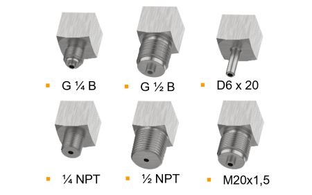
M20 x 1.5, G 1/2 B, 1/2 NPT, וכן flanges פתוחים: 1" class 150 RF, 2" class 150 RF, 1" class 300 RF, DN 25 PN 40 ו-DN 50 PN 40.
האם המכשיר מתאים למדיה אגרסיביים?
כן — הוא מיועד למדיה גזיים ונוזליים אגרסיביים, צמיגיים במיוחד או מזוהמים, עם חלקים רטובים מ-Stainless steel 316L, NiCr alloy (Inconel), PTFE, Hastelloy, Monel, Tantalum או Gold.
מהם גבולות הטמפרטורה?
טמפרטורת סביבה: -20 … +70 °C; טמפרטורת מדיום: -20 … +100 °C.
האם ניתן להשתמש במכשיר באזורים מסוכנים (Ex)?
כן — קיימים דגמים עם מגעים אינדוקטיביים עם אישורי ATEX ו-IECEx: II 2G Ex ia IIC T6/T5/T4 Gb לגז ו-II 2D Ex ia IIIB T135°C Db לאבק, וכן EAC, NEPSI ואישורים נוספים.
מה מבדיל את ה-PGS43 ממדי לחץ אחרים עם מגעים?
זהו מד דיאפרגמה (ולא מד בורדון), ולכן הוא מתאים לטווחים נמוכים החל מ-0 … 25 mbar ולמדיה צמיגיים או מזוהמים, תוך עמידות גבוהה בעומס יתר של פי 10, עם עד 4 מגעי מיתוג לכל מכשיר.
הרכיבו PGS43.1X0 לפי המשימה
המק״ט נבנה אוטומטית. בספק — פנו למהנדס; נסייע לפי פרמטרי הקו.
- Nominal size100
- switchmagnetic snap action switch, model 821
- first switch operationmakes (1)
- second switch operationwithout
- Explosion protectionwithout
- Electrical connectionplug sidewise
- Contact designwithout
- Unit of outer Scalembar
- Scale range—
- 2nd Scale or Special Scalewithout
- Overpressure safety5 x Full scale value, max 40 bar
- Process connection—
- Diaphragm Materialstainless steel
- Lower Body MaterialStainless-Steel
- Connection locationlower mount
- Liquid Damping (case filling)—
- Case—
- Restrictorwithout
- Special design featureswithout
סיימו את התצורה
בחרו את כל האפשרויות כדי לשלוח בקשה.
| דגם | PGS43.100 |
| סדרה | PGS43 |
| תת-קטגוריה | Diaphragm pressure gauge with switch contacts |
| טווח לחץ | 0…25 mbar · 0…40 mbar · 0…60 mbar · 0…100 mbar · 0…160 mbar · 0…250 mbar · 0…400 mbar · 0…600 mbar · 0…1000 mbar · 0…0.6 bar · 0…1 bar · 0…1.6 bar · 0…2.5 bar · 0…4 bar · 0…6 bar · 0…10 bar · 0…16 bar · 0…25 bar · -0.6…0 bar · -1…0 bar · -1…0.6 bar · -1…1 bar · -1…1.5 bar · -1…2 bar · -1…3 bar · -1…5 bar · -1…9 bar · -1…10 bar · -1…15 bar · -1…24 bar · 0…10 psi · 0…15 psi · 0…30 psi · 0…60 psi · 0…100 psi · 0…150 psi · 0…160 psi · 0…200 psi · 0…250 psi · 0…300 psi · 0…400 psi · -25…0 mbar · -40…0 mbar · -60…0 mbar · -100…0 mbar · -160…0 mbar · -250…0 mbar · -400…0 mbar · -600…0 mbar · -1000…0 mbar · -5…20 mbar · -10…15 mbar · -15…25 mbar · -20…40 mbar · -30…30 mbar · -40…60 mbar · -50…200 mbar · -60…100 mbar · -100…150 mbar · -125…125 mbar · -150…250 mbar · -250…750 mbar · -400…600 mbar · -500…500 mbar · -600…400 mbar · -750…250 mbar · -800…200 mbar · -30…15 inHg · -30…60 inHg · -30…100 inHg · -30…160 inHg · -30…200 inHg · -30…300 inHg · -15…0 inHg · -30…0 inHg |
| מחלקת דיוק | 1.6 |
| תקן דיוק | EN 837-3 |
| חיבור תהליך | M20 x 1.5Open connecting flange 1" class 150, RFOpen connecting flange 2" class 150, RFOpen connecting flange 1" class 300, RFOpen connecting flange DN 25 PN 40Open connecting flange DN 50 PN 40G ½ B½ NPTG 1/2 B1/2 NPT |
| טמפ׳ תהליך | −20…+100 °C |
| אות יציאה | Magnetic snap-action contact · Inductive contact · Electronic contact · Reed switch |
| חיבור חשמלי | Cable socket M20x1.5 |
| פונקציית מתג | Normally open, Normally closed, Change-over |
| מגעי מתג | 4 |
| חומר מארז | Stainless steel 1.4301 (304), Stainless steel 1.4571 (316 Ti) |
| חומר חלקים רטובים | Stainless steel 316L, NiCr alloy (Inconel), PTFE, Hastelloy, Monel, Tantalum, Gold |
| חומר אטם | FPM/FKM |
| טמפ׳ סביבה | −20…+70 °C |
| דרגת הגנה IP | IP65 |
| תקנים | CERoHSCRNEN 837-3DIN 16085 |
| הגנת התפוצצות | II 2G Ex ia IIC T6/T5/T4 GbII 2D Ex ia IIIB T135°C DbEx ia IIC T6/T5/T4 GbEx ia IIIB T135°C DbATEX directive: Gas II 2G Ex ia IIC T6/T5/T4 Gb, Dust II 2D Ex ia IIIB T135℃ DbIECEx: Gas Ex ia IIC T6/T5/T4 Gb, Dust Ex ia IIIB T135℃ DbEACEx UkraineNEPSIPAC KazakhstanMChSPAC UkrainePAC Uzbekistan |
| קוטר חוגה | 100 mm |
| שפות גיליון נתונים | EN |
| Scale range | Overload safety 1) | Vacuum-resist- ant to -1 bar |
|---|---|---|
| mbar | ||
| 0 ... 25 | ■ 125 ■ 250 | Selectable |
| 0 ... 40 | ■ 200 ■ 400 | Selectable |
| 0 ... 60 | ■ 300 ■ 600 | Selectable |
| 0 ... 100 | ■ 500 ■ 1,000 | Selectable |
| 0 ... 160 | ■ 800 ■ 1,600 | Selectable |
| 0 ... 250 | ■ 1,250 ■ 2,500 | Selectable |
| 0 ... 400 | ■ 2,000 ■ 4,000 | Selectable |
| 0 ... 600 | ■ 3,000 ■ 6,000 | Selectable |
| 0 ... 1,000 | ■ 5,000 ■ 10,000 | Selectable |
| bar | ||
| 0 ... 0.6 | ■ 3 ■ 6 | Selectable |
| 0 ... 1 | ■ 5 ■ 10 | Selectable |
| 0 ... 1.6 | ■ 8 ■ 16 | Selectable |
| 0 ... 2.5 | ■ 12.5 ■ 25 | Selectable |
| 0 ... 4 | ■ 20 ■ 40 | Yes |
| 0 ... 6 | ■ 30 ■ 40 | Yes |
| 0 ... 10 | 40 | Yes |
| 0 ... 16 | 40 | Yes |
| 0 ... 25 | 40 | Yes |
| mbar | bar |
|---|---|
| -25 ... 0 | -0.6 ... 0 |
| -40 ... 0 | -1 ... 0 |
| -60 ... 0 | psi |
| -100 ... 0 | -15 inHg ... 0 |
| -160 ... 0 | -30 inHg ... 0 |
| -250 ... 0 | |
| -400 ... 0 | |
| -600 ... 0 | |
| -1,000 ... 0 |
| Scale range | Overload safety 1) | Vacuum-resist- ant to -1 bar | |
|---|---|---|---|
| psi | |||
| 0 ... 10 | ■ 50 ■ 100 | Selectable | |
| 0 ... 15 | ■ 75 ■ 150 | Selectable | |
| 0 ... 30 | ■ 150 ■ 300 | Selectable | |
| 0 ... 60 | ■ 300 ■ 600 | Yes | |
| 0 ... 100 | ■ 500 ■ 1,000 | Yes | |
| 0 ... 150 | ■ 750 ■ 1,500 | Yes | |
| 0 ... 160 | ■ 800 ■ 1,600 | Yes | |
| 0 ... 200 | ■ 1,000 ■ 2,000 | Yes | |
| 0 ... 250 | ■ 1,250 ■ 2,500 | Yes | |
| 0 ... 300 | ■ 1,500 ■ 3,000 | Yes | |
| 0 ... 400 | ■ 2,000 ■ 4,000 | Yes | |
| +/- scale ranges 2) | |||
| Scale range | |||
| mbar | bar | ||
| -5 ...+20 | -1 ... +0.6 | ||
| -10 ...+15 | -1 ...+1 | ||
| -15 ...+25 | -1 ... +1.5 | ||
| -20 ...+40 | -1 ...+2 | ||
| -30 ...+30 | -1 ...+3 | ||
| -40 ...+60 | -1 ...+5 | ||
| -50 ...+200 | -1 ...+9 | ||
| -60 ...+100 | -1 ...+10 | ||
| -100 ...+150 | -1 ...+15 | ||
| -125 ...+125 | -1 ...+24 | ||
| -150 ...+250 | psi | ||
| -250 ...+750 | -30 inHg ...+15 | ||
| -400 ...+600 | -30 inHg ...+60 | ||
| -500 ...+500 | -30 inHg ...+100 | ||
| -600 ...+400 | -30 inHg ...+160 | ||
| -750 ...+250 | -30 inHg ...+200 | ||
| -800 ...+200 | -30 inHg ...+300 |
| Unit | ■ bar ■ psi ■ mbar ■ kg/cm² ■ MPa ■ kPa |
|---|---|
| Other units on request | |
| Overload safety | ■ 5 x full scale value, max. 40 bar ■ 10 x full scale value, max. 40 bar |
| Vacuum resistance | ■ Without ■ Vacuum-resistant to -1 bar |
| Dial | |
| Scale layout | ■ Single scale ■ Dual scale |
| Scale colour | Single scale Black |
| Dual scale Black/Red | |
| Material | Aluminium |
| Customer-specific version | Other scales, e.g. with red mark, circular arcs or circular sectors, on request →Alternatively, adhesive label set for red and green circular arcs; see data sheet AC08.03 |
| Instrument pointer | Aluminium, black |
| Set pointer | Aluminium, red |
הצגת הכול (20)
| Process connection | |
|---|---|
| Standard | ■ EN 837 ■ ANSI / ASME B1.20.1 ■ ASME B16.5 ■ EN 1092-1, form B |
| Size 1) | |
| EN 837 | ■ G½B ■ M20 x 1.5 |
| ANSI / ASME B1.20.1 | ■ ½NPT |
| ASME B16.5 | ■ Open connecting flange 1" class 150, RF ■ Open connecting flange 2" class 150, RF ■ Open connecting flange 1" class 300, RF |
| EN 1092-1, form B | ■ Open connecting flange DN 25 PN 40 ■ Open connecting flange DN 50 PN 40 |
| Materials (wetted) | |
| Diaphragm element | ■ Stainless steel 316L, for span ≤ 0.25 bar ■ NiCr alloy (Inconel), for span > 0.25 bar |
| Process connection with lower measuring flange | Stainless steel 316L |
| Coating / Lining 2) 3) | ■ Without ■ PTFE ■ Hastelloy ■ Monel ■ Tantalum ■ Gold (only for diaphragm element) |
| Other materials on request | |
| Seal 4) | FPM/FKM |
| Output signal | |
|---|---|
| Type of contact | ■ Magnetic snap-action contact, model 821 (→ See page 7) ■ Inductive contact, model 831 (→ See page 8) ■ Electronic contact, model 830 E (→ See page 9) ■ Reed switch, model 851 (→ See page 10) |
| Switching technology | |
| Magnetic snap-action contact, model 821 | ■ No control unit and no supply voltage required ■ Direct switching up to 250 V, 1 A |
| Inductive contact, model 831 | ■ Suitable for use in hazardous areas with corresponding control unit (model 904.xx) ■ Long service life due to non-contact sensor ■ Low influence on the indication accuracy ■ Fail-safe switching at high switching frequency ■ Insensitive to corrosion ■ Also available in safety version |
| Electronic contact, model 830 E | ■ For direct triggering of a programmable logic controller (PLC) ■ Long service life due to non-contact sensor ■ Low influence on the indication accuracy ■ Fail-safe switching at high switching frequency ■ Insensitive to corrosion |
| Reed switch, model 851 | ■ No control unit and no supply voltage required ■ Direct switching up to 250 V, 1 A ■ For direct triggering of a programmable logic controller (PLC) ■ Free from wear as without contact |
| Contact setting | ■ Contact(s) adjustable, adjustment key attached to cable socket ■ Contact(s) fixed, without adjustment lock 1) ■ Adjustment lock sealable (tamper-proof) ■ Adjustment lock sealed (tamper-proof) 1) ■ Captive adjustment key with the adjustment lock connected |
| Type of contact | Magnetic snap-action contact |
|---|---|
| Switching technology | ■ No control unit and no supply voltage required ■ Direct switching up to 250 V, 1 A |
| Number of switch contacts | |
| Span ≥ 25 mbar ...< 40 mbar 1) | Max. 2 switch contacts |
| Span ≥ 40 mbar | Max. 4 switch contacts |
| Switching function | ■ Separate circuits with ≥ 2 switches ■ Cable break monitoring with parallel resistance (47 kΩ or 100 kΩ) |
| The switching function of each switch is indicated by index 1, 2 or 3 | |
| Model 821.1 | Normally open (clockwise pointer motion) |
| Model 821.2 | Normally closed (clockwise pointer motion) |
| Model 821.3 | Change-over; one contact breaks and one contact makes simultaneously when pointer reaches set point |
| Switch point setting | Set pointers of the contact pressure gauges are freely adjustable over the full scale range |
| Setting range (recommended) | 25 ... 75 %of span (0 ... 100 %onrequest) |
| Distance between switch points | Recommended minimum distance between 2 contacts: 20 %of span |
| Switch hysteresis | 2 ... 5 %(typical) |
| Switching current | 0.02 ... 0.3 A (resistive load) Permissible switch-on and switch-off current: ≤ 0.5 A |
| Switching voltage | AC/DC 24 ...250V |
| Switching power 2) | |
| Unfilled instruments | ≤ 30 W, ≤ 50VA |
| Filled instruments | ≤ 20 W, ≤ 20VA |
| Contact material | Silver-nickel, gold-plated |
| Switching voltage | Unfilled instruments | Filled instruments | ||||
|---|---|---|---|---|---|---|
| Resistive load | Inductive load | Resistive load | Inductive load | |||
| Direct current | Alternating current | cos ϕ>0.7 | Direct current | Alternating current | cos ϕ>0.7 | |
| DC 220 V / AC 230 V | 100mA | 120mA | 65mA | 65mA | 90mA | 40mA |
| DC 110 V / AC 110 V | 200mA | 240mA | 130mA | 130mA | 180mA | 85mA |
| DC 48 V / AC 48 V | 300mA | 450mA | 200mA | 190mA | 330mA | 130mA |
| DC 24 V / AC 24 V | 400mA | 600mA | 250mA | 250mA | 450mA | 150mA |
| Type of contact | Inductive contact |
|---|---|
| Switching technology | ■ Suitable for use in hazardous areas with corresponding control unit (model 904.xx) ■ Long service life due to non-contact sensor ■ Low influence on the indication accuracy ■ Fail-safe switching at high switching frequency ■ Insensitive to corrosion ■ Also available in safety version |
| Number of switch contacts | |
| Span ≥ 25 mbar 1) | Max. 3 switch contacts |
| Switching function | Contact versions: ■ 831-N ■ 831-SN, safety version 2) ■ 831-S1N, safety version 2) , inverted signal The switching function of each switch is indicated by index 1 or 2 |
| Model 831.1 | Normally open (clockwise pointer motion) |
| Model 831.2 | Normally closed (clockwise pointer motion) |
| Switch point setting | Set pointers of the contact pressure gauges are freely adjustable over the full scale range |
| Setting range (recommended) | 10 ... 90 %of span (0 ... 100 %onrequest) |
| Distance between switch points | Up to 2 contacts can be set to an identical set point. For a version with 3 contacts this is not possible.The left (no. 1) or right (no. 3) contact may not be set to the same set point as the other 2 contacts.The required displacement is approx. 30°, optionally to the right or to the left. |
| Switching current | Depending on the control unit used (→ See data sheet AC 08.04) |
| Switching voltage | Depending on the control unit used (→ See data sheet AC 08.04) |
| Switching power | Depending on the control unit used (→ See data sheet AC 08.04) |
| Permissible temperature ranges in hazardous areas | |
| T6 | -20 ...+60 °C |
| T5 ...T1 | -20 ...+70 °C |
| T135°C | -20 ...+70 °C |
| Model | Version | Ex version |
|---|---|---|
| 904.28 KFA6 - SR2 - Ex1.W | 1 contact | Yes |
| 904.29 KFA6 - SR2 - Ex2.W | 2 contacts | Yes |
| 904.30 KHA6 - SH - Ex1 | 1 contact | Yes - Safety version |
| 904.33 KFD2 - SH - Ex1 | 1 contact | Yes - Safety version |
| 904.25 MSR 010-I | 1 contact | No |
| 904.26 MSR 020-I | 2 contacts | No |
| 904.27 MSR 011-I | Two-point control | No |
| Type of contact | Electronic contact (PNP transistor) |
|---|---|
| Switching technology | ■ For direct triggering of a programmable logic controller (PLC) ■ Long service life due to non-contact sensor ■ Low influence on the indication accuracy ■ Fail-safe switching at high switching frequency ■ Insensitive to corrosion |
| Number of switch contacts | |
| Span ≥ 25 mbar 1) | Max. 3 switch contacts |
| Switching function | Contact versions: ■ 2-wire system ■ 3-wire system |
| The switching function of each switch is indicated by index 1 or 2 | |
| Model 830 E.1 | Normally open (clockwise pointer motion) |
| Model 830 E.2 | Normally closed (clockwise pointer motion) |
| Setting range (recommended) | 10 ... 90 %of span (0 ... 100 %onrequest) |
| Distance between switch points | Up to 2 contacts can be set to an identical set point. For a version with 3 contacts this is not possible.The left (no. 1) or right (no. 3) contact may not be set to the same set point as the other 2 contacts.The required displacement is approx. 30°, optionally to the right or to the left. |
| Switching current | ≤ 100mA |
| Switching voltage | DC 10 ...30V |
| Type of contact 1) 2) | Bistable reed switch |
|---|---|
| Switching technology | ■ No control unit and no supply voltage required ■ Direct switching up to 250 V, 1 A ■ For direct triggering of a programmable logic controller (PLC) ■ Free from wear as without contact |
| Number of switch contacts | |
| NS 100 [4"] | Max. 2 switch contacts |
| NS 160 [6"] 3) | 1 switch contact |
| Switching function | ■ Separate circuits with ≥ 2 switches ■ Cable break monitoring with parallel resistance (47 kΩ or 100 kΩ) |
| The switching function of each switch is indicated by index 1, 2 or 3 | |
| Model 851.1 | Normally open (clockwise pointer motion) |
| Model 851.2 | Normally closed (clockwise pointer motion) |
| Model 851.3 | Change-over; one contact breaks and one contact makes simultaneously when pointer reaches set point |
| Switch point setting | Set pointers of the contact pressure gauges are freely adjustable over the full scale range |
| Setting range (recommended) | 10 ... 90 %of span |
| Distance between switch points | When using two contacts, these cannot be set to the same point. Depending on the switch- ing function, a minimum clearance of 15 ... 30° is required. |
| Switch hysteresis | 3 ...5% |
| Switching current | ≤ AC/DC 1 A |
| Switching voltage | ≤ AC/DC 250V |
| Switching power | ≤ 60 W, 60VA |
| Contact material | Rhodium |
| Transport current | AC/DC 2 A |
| Inductive load cosϕ | 1 |
| Contact resistance (static) | 100mΩ |
| Insulation resistance | 109Ω |
| Breakdown voltage | DC 1,000V |
| Switching time incl. contact chatter | 4.5 ms |
| Connection type | ■ Cable socket, black PerVDE 0110 insulation group C/250V Cable gland M20 x 1.5 ■ Connector (instead of cable socket) |
|---|---|
| Wire cross-section | 6 screw terminals + PE for 2.5 mm² |
| Cable diameter | →See dimensions |
| Pin assignment | Connection details are given on the product label of the instrument. Connection termi- nals and ground terminals are appropriately marked. |
| Material | PA 6 (polyamide) |
| Medium temperature range | ■ +100 °C [+212 °F] maximum ■ +200 °C [+392 °F] maximum |
|---|---|
| Ambient temperature range | -20 ...+60 °C [-4 ... 140 °F] |
| Storage temperature range | -20 ...+60 °C [-4 ... 140 °F] |
| Pressure limitation | |
| Steady | Full scale value |
| Fluctuating | 0.9 x full scale value |
| Ingress protection per IEC/EN 60529 | ■ IP54 ■ IP65 1) ■ IP66 2) (ingress protection of the case) |
| Logo | Description | Region |
|---|---|---|
| EU | declaration of conformity | European Union |
| EMCdirective | ||
| Low voltage directive | directive | |
| RoHS - | CRN Safety (e.g. electr. safety, overpressure, ...) | Canada |
| Logo | Description | Region |
|---|---|---|
| EU declaration of conformity | European Union | |
| ATEX directive 1) Hazardous areas IECEx 1) | International | |
| EAC EMCdirective | Eurasian Economic Community | |
| Ex Ukraine Hazardous areas 1) | Ukraine | |
| NEPSI Hazardous areas 1) | China | |
| PAC Kazakhstan Metrology, measurement technology | Kazakhstan | |
| - | MChS Permission for commissioning | Kazakhstan |
| PAC Ukraine Metrology, measurement technology | Ukraine | |
| PAC Uzbekistan Metrology, measurement technology | Uzbekistan |
| Certificates | ■ 2.2 test report per EN 10204 (e.g. state-of-the-art manufacturing, indication accuracy) ■ 3.1 inspection certificate per EN 10204 (e.g. indication accuracy) |
|---|---|
| Recommended calibration interval | 1 year (dependent on conditions of use) |
| Process connection G | Scale range | Dimensions inmm | ||||||
|---|---|---|---|---|---|---|---|---|
| Ø d | h | S2 | S3 | S4 | S5 | S6 | ||
| G½B | ≤ 250 mbar | 160 | 119 | Ø6 | 20 | 3 | 17 | Ø17.5 |
| G½B | > 250 mbar | 100 | 117 | Ø6 | 20 | 3 | 17 | Ø17.5 |
| ½NPT | ≤ 250 mbar | 160 | 118 | - | 19 | - | - | - |
| ½NPT | > 250 mbar | 100 | 116 | - | 19 | - | - | - |
| Type of contact | Dimensions inmm | |
|---|---|---|
| X | Y | |
| Single or double contact | 88 | 55 |
| Double (change-over) contact | 113 | 80 |
| Triple contact | 96 | 63 |
| Quadruple contact | 113 | 80 |
| Process connection G | Scale range | Dimensions inmm | ||||||
|---|---|---|---|---|---|---|---|---|
| Ø d | h | S2 | S3 | S4 | S5 | S6 | ||
| G½B | ≤ 250 mbar | 160 | 119 | Ø6 | 20 | 3 | 17 | Ø17.5 |
| G½B | > 250 mbar | 100 | 117 | Ø6 | 20 | 3 | 17 | Ø17.5 |
| ½NPT | ≤ 250 mbar | 160 | 118 | - | 19 | - | - | - |
| ½NPT | > 250 mbar | 100 | 116 | - | 19 | - | - | - |
לא מצאתם תשובה בתיעוד? מהנדס יענה במהלך יום עסקים.
שאלו מהנדס →149 מק״טים סטנדרטיים של משפחת PGS43
אם ידוע הקוד — בחרו ישירות. אם לא — השתמשו בתצורה במצב «01».