
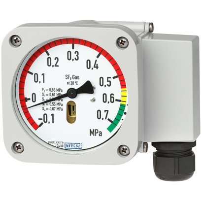
Газовый плотномер с эталонной камерой
Описание
Газовый плотномер GDM-RC-100 предназначен для контроля плотности газа SF₆ в высоковольтном оборудовании. Принцип работы основан на сравнении с приваренным эталонным газовым объёмом, что обеспечивает точную изохорную, температурно-компенсированную индикацию и коммутацию во всём диапазоне температур. Прибор выбирается там, где требуется местная индикация плотности на циферблате 100 мм и сигнализация при достижении заданных предельных значений.
Особенности
- Точный изохорный режим, температурно-компенсированное переключение и отображение во всём диапазоне температур
- Полная локальная индикация плотности и диапазона вакуума на циферблате 100 мм
- Повышенная безопасность установки благодаря самодиагностике
- Подготовлен для любых альтернативных газов
- Очень высокая долговременная стабильность благодаря приваренному опорному газовому объёму
Вопросы и ответы
Какой диапазон давления измеряет прибор?
Доступны диапазоны 0 … 12,5 bar, −1 … 5 bar, −1 … 9 bar и −1 … 11,5 bar.
Какова точность измерения?
Класс точности составляет ±70 mbar до ±200 mbar в зависимости от диапазона и температуры.
Какое присоединение к процессу предусмотрено?
Резьба G ½ B, в том числе исполнение G ½ B по EN 837.
Для какого газа предназначен плотномер?
Прибор предназначен для контроля плотности газа SF₆ в высоковольтном оборудовании и подготовлен для работы с любыми альтернативными газами.
В каком температурном диапазоне работает прибор?
Диапазон температуры окружающей среды составляет −40 … +80 °C, при этом индикация и коммутация температурно-компенсированы по всей шкале.
Какая степень защиты корпуса?
Корпус имеет степень защиты IP65/IP67.
Есть ли взрывозащищённое исполнение или уровень SIL?
По предоставленным данным взрывозащищённое исполнение не указано; из сертификатов заявлены RoHS, EAC и CE.
Чем модель с эталонной камерой отличается от других контроллеров плотности?
Приваренный эталонный газовый объём обеспечивает очень высокую долговременную стабильность и точную изохорную температурную компенсацию без внешних датчиков температуры, а также полную местную индикацию плотности и диапазона вакуума на циферблате 100 мм.
| Модель | GDM-RC-100 |
| Серия | GDM-RC |
| Подтип | With reference chamber |
| Диапазон давления | 0…12.5 bar · -1…5 bar · -1…9 bar · -1…11.5 bar |
| Опорная температура плотности | 20 °C |
| Класс точности | ±70 mbar to ±200 mbar depending on range and temperature |
| Технологическое присоединение | G ½ BG ½ B per EN 837 |
| Выходной сигнал | Potential-free change-over contacts |
| Переключающие контакты | 4 |
| Материал смачиваемых частей | Stainless steel |
| Темп. окружающей среды | −40…+80 °C |
| Степень защиты IP | IP65/IP67 |
| Вес | 1.25 kg |
| Сертификаты | RoHSEACCE |
| Температурная компенсация | Да |
| Языки datasheet | EN, DE |
| Nominal size of the optical indication | 100 mm[3.94 in] |
|---|---|
| Window | Laminated safety glass |
| Case and cover | Aluminium die-casting, powder-coated |
| Type of measuring element | Bellows measuring system with reference chamber |
|---|
| -1 ...+5 bar at 20 °C [-14.50 ... +72.51 psi at 68 °F] | ■ ±70 mbar [±1.01 psi] at calibration pressure at 20 °C [68 °F], gaseous phase ■ ±100 mbar [±1.45 psi] at calibration pressure at -30 …+50 °C | |
|---|---|---|
| -1 ...+9 bar at 20 °C [-14.50 ... +130.53 psi at 68 °F] | ■ ±100 mbar [±1.45 psi] at calibration pressure at 20 °C [68 °F], gaseous phase ■ ±150 mbar [±2.17 psi] at calibration pressure at -30 …+50 °C [-22 ...+122 °F], gaseous phase | |
| -1 ... +11.5 bar at 20 °C [-14.50 ... +166.79 psi at 68 °F] | ■ ±150 mbar [±2.17 psi] at calibration pressure at 20 °C [68 °F], gaseous phase ■ ±200 mbar [±2.90 psi] at calibration pressure at -30 …+50 °C [-22 ...+122 °F], gaseous phase | |
| Accuracies of the switch point | ||
| -1 ...+5 bar at 20 °C [-14.50 ... +72.51 psi at 68 °F] | ■ ±70 mbar [±1.01 psi] at calibration pressure at 20 °C [68 °F], gaseous phase ■ ±100 mbar [±1.45 psi] at calibration pressure at -30 …+50 °C [-22 ...+122 °F], gaseous phase | |
| -1 ...+9 bar at 20 °C [-14.50 ... +130.53 psi at 68 °F] | ■ ±100 mbar [±1.45 psi] at calibration pressure at 20 °C [68 °F], gaseous phase ■ ±150 mbar [±2.17 psi] at calibration pressure at -30 …+50 °C [-22 ...+122 °F], gaseous phase | |
| -1 ... +11.5 bar at 20 °C [-14.50 ... +166.79 psi at 68 °F] | ■ ±150 mbar [±2.17 psi] at calibration pressure at 20 °C [68 °F], gaseous phase ■ ±200 mbar [±2.90 psi] at calibration pressure at -30 …+50 °C [-22 ...+122 °F], gaseous phase | |
| Switch hysteresis | Measuring range | Hysteresis level |
| -1 ...+5 bar at 20 °C [-14.50 ... +72.51 psi at 68 °F] | Typically < 90 mbar 1) [< 1.30 psi] | |
| -1 ... +7.5 bar at 20 °C [-14.50 ... +108.77 psi at 68 °F] | Typically < 150 mbar 1) [< 2.17psi] | |
| -1 ... +11.5 bar at 20 °C [-14.50 ... +166.79 psi at 68 °F] | Typically < 220 mbar 1) [< 3.19psi] | |
| Lower switch hysteresis on request | ||
| Reference conditions | ||
| Storage temperature | -50 ...+80 °C [-58 ...+176 °F] | |
| Relative humidity, condensation | ≤ 95 %r.h. (non-condensing) |
| Measuring range | |
|---|---|
| Measuring range | 0 ... 12.5 bar abs. at 20 °C [0 ... 181.29 psi abs. at 68 °F] SF₆ gas |
| Pressure limitation | |
| Minimum bursting strength | > 36 bar [522 psi] |
| Maximum overpressure | 1.43 times the measuring range |
| Dial | |
| Scale range | End of measuring range ■ 1.3 bar or 1.8 bar [18.85 psi or 26.10 psi] above the first switch point below the filling pressure ■ Numbering: Ends at 900 mbar [13.05 psi] above the first switch point below the filling pressure |
| Scale graduation | ■ Single scale (divided into sections of different colours) ■ Double scale (divided into sections of different colours) ■ Triple scale (divided into sections of different colours) |
| Scale colour | Custom |
| Pointer stop pin | Without |
| Material | Aluminium |
| Pointer | Aluminium, black |
Смотреть все (15)
| Connection type | 12-pin TTI plug-in terminal | ||
|---|---|---|---|
| Wire cross-section | ■ Min. 0.5 mm² ■ Max.2.5mm 2 | ||
| Grounding | Grounding in cable socket available | ||
| Switch model | Potential-free change-over contacts | ||
| Number | ■ 1 switch contact ■ 2 switch contacts ■ 3 switch contacts ■ 4 switch contacts Up to 4 switch contacts possible as change-over contact | ||
| Switching directions | ■ Falling density ■ Rising density | ||
| Switch points | In accordance with customer specification, maximum difference of lowest to highest contact: 4 bar [58.01 psi] | ||
| Electrical characteristics | Switching voltage [V] | Resistive load [A] | Inductive load [A] |
| ≤ DC 30 | 5 1) | 3 1) | |
| ≤ DC 50 | 1 | 1 | |
| ≤ DC 75 | 0.75 | 0.75 | |
| ≤ DC 125 | 0.5 | 0.04 | |
| ≤ DC 250 | 0.25 | 0.03 | |
| ≤ AC 125 | 5 1) | 2 1) | |
| ≤ AC 250 | 5 1) | 2 1) |
| Minimum switching voltage and current | 20 V, 10mA |
|---|---|
| Calibration pressure | First switch point below filling pressure |
| Switching function | Change-over contact |
| Circuits | Galvanically isolated |
| Maximum number of cycles | 10,000 mechanical and electrical |
| Insulation resistance of contact | > 100MΩ |
| Material (wetted) | Stainless steel |
|---|---|
| Material (in contact with the environment) | ■ Stainless steel ■ Aluminium die-casting with powder coating |
| Place of use | Indoor/Outdoor |
|---|---|
| Altitude | Up to 2,000 m[6,562 ft] above sea level |
| Medium temperature range / limit | -40 ...+80 °C [-40 ...+176 °F], gaseous phase |
| Operating temperature | -40 ...+80 °C [-40 ...+176 °F], gaseous phase |
| Ambient temperature range / limit | -40 ...+80 °C [-40 ...+176 °F], gaseous phase |
| Storage temperature range | -50 ...+80 °C [-58 ...+176 °F] |
| Relative humidity, condensation | ≤ 95 %r.h. (non-condensing) |
| Helium leak test | < 1*10 -8 mbar*l/s |
| Shock resistance | ■ 50 g/11 ms no contact bouncing at a distance of 200 mbar from the switch point ■ 150 g: no damage in all axes and directions |
| Ingress protection of the complete instrument | ■ IP65 ■ IP67 |
| Permissible pollution degree | 2 (per EN 61010-1) |
| Weight in kg | < 1.25 kg [2.75 lb] |
| Product label | Lasered onto the reference chamber, maximum resistance to weathering |
|---|
| Model | Material | Thread | Sealing range | Tightening torque | Order number |
|---|---|---|---|---|---|
| Switch contacts | Plastic | M25 x 1.5 | 5 ...13mm [0.19 ... 0.51 in] | 8Nm | 2196018 |
| Plastic | M25 x 1.5 | 8 ...17mm [0.31 ... 0.66 in] | 8Nm | 64419018 | |
| Metal | M25 x 1.5 | 9…17mm [0.35 ... 0.66 in] | 10Nm | 64419009 | |
| Metal | M25 x 1.5 | 7…12mm [0.27 ... 0.47 in] | 10Nm | 64423057 |
| Description | Region |
|---|---|
| EU declaration of conformity | European Union |
| LowVoltage Directive | |
| EAC LowVoltage Directive | Eurasian Economic Community |
| Logo | Description |
|---|---|
| - | China RoHS directive |
| Certificates | ■ 2.2 test report per EN 10204 (e.g. state-of-the-art manufacturing, material proof, indication accuracy) ■ 3.1 inspection certificate per EN 10204 (e.g. material proof for wetted metal parts, indication accuracy, calibration certificate) |
|---|---|
| Calibration | Factory calibration certificate |
| Recommended calibration interval | At least every 6 years in accordance with Regulation (EU) No. 517/2014 on fluorinated greenhouse gases |
| Model | Description | Order number |
|---|---|---|
| Optional accessories | ||
| Recalibration valve | Model GLTC-CV ■ Enables easy recalibration of the gas density monitor without dismounting ■ Welded permanently to the instrument or available as loose valve for retrofitting | - |
| Connection cable for switch- ing outputs | ■ Terminal without wiring ■ Connector mounted on the instrument side, cable with loose ends ■ Various cable lengths on request | - |
| Description | Order number |
|---|---|
| Adapter from test connection (M26 x 1.5) to quick coupling | 14146937 |
| Protective cap for test connection (M26 x 1.5) | 14193772 |
| Calibration system for SF₆ gas density measuring instruments, model BCS-10 SeeWIKA data sheet SP 60.08 | - |
| Calibration system for SF₆ gas density measuring instruments, model ACS-10 SeeWIKA data sheet SP 60.15 | - |
Не нашли ответа в документации? Инженер ответит в течение рабочего дня.
Спросить инженера →