
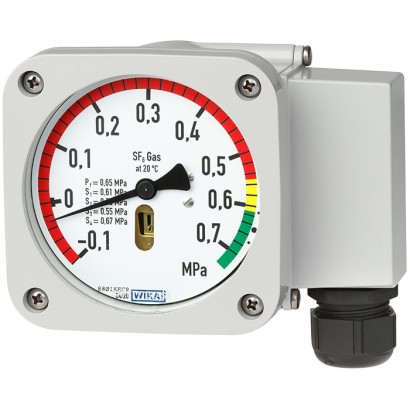
מוניטור צפיפות גז עם תא ייחוס
תיאור
מוניטור הצפיפות GDM-RC-100 מיועד לניטור צפיפות גז SF₆ בציוד מתח גבוה, באמצעות תא ייחוס מרותך המבטיח פיצוי טמפרטורה מדויק. ההתקן מספק אינדיקציה מקומית של הצפיפות והריק על שעון בקוטר 100 מ״מ, ומפעיל התראה כאשר מושגים ערכי סף מוגדרים. הוא נבחר למתקני מתח גבוה שבהם ניטור צפיפות הגז הוא פרמטר תפעולי קריטי.
תכונות מיוחדות
- איזוכור מדויק, החלפה ותצוגה עם פיצוי טמפרטורה בכל טווח הטמפרטורות
- תצוגה מקומית מלאה של טווח הצפיפות והריק בחוגה של 100 מ"מ
- בטיחות מוגברת של המתקן באמצעות אבחון עצמי
- מוכן לכל גז חלופי
- יציבות ארוכת טווח גבוהה מאוד באמצעות נפח גז ייחוס מרותך
שאלות ותשובות
מהו טווח הלחץ של ה-GDM-RC-100?
ההתקן זמין בטווחים 0 … 12.5 bar, -1 … 5 bar, -1 … 9 bar ו--1 … 11.5 bar.
מהי הדיוק של המוניטור?
מחלקת הדיוק היא ±70 mbar עד ±200 mbar, בהתאם לטווח ולטמפרטורה.
אילו חיבורי תהליך זמינים?
G ½ B, וכן G ½ B לפי EN 837.
מהם חומרי החלקים במגע עם המדיום?
החלקים במגע עם המדיום עשויים פלדת אל-חלד.
מהו טווח הטמפרטורה הסביבתי ודרגת ההגנה?
טווח הטמפרטורה הסביבתי הוא -40 … +80 °C, ודרגת ההגנה היא IP65/IP67.
כמה מגעי מיתוג יש להתקן ומה סוג הפלט?
להתקן 4 מגעי מיתוג, בצורת מגעי החלפה ללא פוטנציאל.
מה מייחד את ה-GDM-RC-100 מדגמים אחרים?
הוא כולל תא ייחוס מרותך המספק פיצוי טמפרטורה מדויק מסוג איזוכור ויציבות ארוכת טווח גבוהה, יחד עם אבחון עצמי ותמיכה בגזים חלופיים.
אילו אישורים יש להתקן?
ההתקן מאושר RoHS, EAC ו-CE.
| דגם | GDM-RC-100 |
| סדרה | GDM-RC |
| תת-קטגוריה | With reference chamber |
| טווח לחץ | 0…12.5 bar · -1…5 bar · -1…9 bar · -1…11.5 bar |
| טמפרטורת ייחוס לצפיפות | 20 °C |
| מחלקת דיוק | ±70 mbar to ±200 mbar depending on range and temperature |
| חיבור תהליך | G ½ BG ½ B per EN 837 |
| אות יציאה | Potential-free change-over contacts |
| מגעי מתג | 4 |
| חומר חלקים רטובים | Stainless steel |
| טמפ׳ סביבה | −40…+80 °C |
| דרגת הגנה IP | IP65/IP67 |
| משקל | 1.25 kg |
| תקנים | RoHSEACCE |
| פיצוי טמפרטורה | כן |
| שפות גיליון נתונים | EN, DE |
| Nominal size of the optical indication | 100 mm[3.94 in] |
|---|---|
| Window | Laminated safety glass |
| Case and cover | Aluminium die-casting, powder-coated |
| Type of measuring element | Bellows measuring system with reference chamber |
|---|
| -1 ...+5 bar at 20 °C [-14.50 ... +72.51 psi at 68 °F] | ■ ±70 mbar [±1.01 psi] at calibration pressure at 20 °C [68 °F], gaseous phase ■ ±100 mbar [±1.45 psi] at calibration pressure at -30 …+50 °C | |
|---|---|---|
| -1 ...+9 bar at 20 °C [-14.50 ... +130.53 psi at 68 °F] | ■ ±100 mbar [±1.45 psi] at calibration pressure at 20 °C [68 °F], gaseous phase ■ ±150 mbar [±2.17 psi] at calibration pressure at -30 …+50 °C [-22 ...+122 °F], gaseous phase | |
| -1 ... +11.5 bar at 20 °C [-14.50 ... +166.79 psi at 68 °F] | ■ ±150 mbar [±2.17 psi] at calibration pressure at 20 °C [68 °F], gaseous phase ■ ±200 mbar [±2.90 psi] at calibration pressure at -30 …+50 °C [-22 ...+122 °F], gaseous phase | |
| Accuracies of the switch point | ||
| -1 ...+5 bar at 20 °C [-14.50 ... +72.51 psi at 68 °F] | ■ ±70 mbar [±1.01 psi] at calibration pressure at 20 °C [68 °F], gaseous phase ■ ±100 mbar [±1.45 psi] at calibration pressure at -30 …+50 °C [-22 ...+122 °F], gaseous phase | |
| -1 ...+9 bar at 20 °C [-14.50 ... +130.53 psi at 68 °F] | ■ ±100 mbar [±1.45 psi] at calibration pressure at 20 °C [68 °F], gaseous phase ■ ±150 mbar [±2.17 psi] at calibration pressure at -30 …+50 °C [-22 ...+122 °F], gaseous phase | |
| -1 ... +11.5 bar at 20 °C [-14.50 ... +166.79 psi at 68 °F] | ■ ±150 mbar [±2.17 psi] at calibration pressure at 20 °C [68 °F], gaseous phase ■ ±200 mbar [±2.90 psi] at calibration pressure at -30 …+50 °C [-22 ...+122 °F], gaseous phase | |
| Switch hysteresis | Measuring range | Hysteresis level |
| -1 ...+5 bar at 20 °C [-14.50 ... +72.51 psi at 68 °F] | Typically < 90 mbar 1) [< 1.30 psi] | |
| -1 ... +7.5 bar at 20 °C [-14.50 ... +108.77 psi at 68 °F] | Typically < 150 mbar 1) [< 2.17psi] | |
| -1 ... +11.5 bar at 20 °C [-14.50 ... +166.79 psi at 68 °F] | Typically < 220 mbar 1) [< 3.19psi] | |
| Lower switch hysteresis on request | ||
| Reference conditions | ||
| Storage temperature | -50 ...+80 °C [-58 ...+176 °F] | |
| Relative humidity, condensation | ≤ 95 %r.h. (non-condensing) |
| Measuring range | |
|---|---|
| Measuring range | 0 ... 12.5 bar abs. at 20 °C [0 ... 181.29 psi abs. at 68 °F] SF₆ gas |
| Pressure limitation | |
| Minimum bursting strength | > 36 bar [522 psi] |
| Maximum overpressure | 1.43 times the measuring range |
| Dial | |
| Scale range | End of measuring range ■ 1.3 bar or 1.8 bar [18.85 psi or 26.10 psi] above the first switch point below the filling pressure ■ Numbering: Ends at 900 mbar [13.05 psi] above the first switch point below the filling pressure |
| Scale graduation | ■ Single scale (divided into sections of different colours) ■ Double scale (divided into sections of different colours) ■ Triple scale (divided into sections of different colours) |
| Scale colour | Custom |
| Pointer stop pin | Without |
| Material | Aluminium |
| Pointer | Aluminium, black |
הצגת הכול (15)
| Connection type | 12-pin TTI plug-in terminal | ||
|---|---|---|---|
| Wire cross-section | ■ Min. 0.5 mm² ■ Max.2.5mm 2 | ||
| Grounding | Grounding in cable socket available | ||
| Switch model | Potential-free change-over contacts | ||
| Number | ■ 1 switch contact ■ 2 switch contacts ■ 3 switch contacts ■ 4 switch contacts Up to 4 switch contacts possible as change-over contact | ||
| Switching directions | ■ Falling density ■ Rising density | ||
| Switch points | In accordance with customer specification, maximum difference of lowest to highest contact: 4 bar [58.01 psi] | ||
| Electrical characteristics | Switching voltage [V] | Resistive load [A] | Inductive load [A] |
| ≤ DC 30 | 5 1) | 3 1) | |
| ≤ DC 50 | 1 | 1 | |
| ≤ DC 75 | 0.75 | 0.75 | |
| ≤ DC 125 | 0.5 | 0.04 | |
| ≤ DC 250 | 0.25 | 0.03 | |
| ≤ AC 125 | 5 1) | 2 1) | |
| ≤ AC 250 | 5 1) | 2 1) |
| Minimum switching voltage and current | 20 V, 10mA |
|---|---|
| Calibration pressure | First switch point below filling pressure |
| Switching function | Change-over contact |
| Circuits | Galvanically isolated |
| Maximum number of cycles | 10,000 mechanical and electrical |
| Insulation resistance of contact | > 100MΩ |
| Material (wetted) | Stainless steel |
|---|---|
| Material (in contact with the environment) | ■ Stainless steel ■ Aluminium die-casting with powder coating |
| Place of use | Indoor/Outdoor |
|---|---|
| Altitude | Up to 2,000 m[6,562 ft] above sea level |
| Medium temperature range / limit | -40 ...+80 °C [-40 ...+176 °F], gaseous phase |
| Operating temperature | -40 ...+80 °C [-40 ...+176 °F], gaseous phase |
| Ambient temperature range / limit | -40 ...+80 °C [-40 ...+176 °F], gaseous phase |
| Storage temperature range | -50 ...+80 °C [-58 ...+176 °F] |
| Relative humidity, condensation | ≤ 95 %r.h. (non-condensing) |
| Helium leak test | < 1*10 -8 mbar*l/s |
| Shock resistance | ■ 50 g/11 ms no contact bouncing at a distance of 200 mbar from the switch point ■ 150 g: no damage in all axes and directions |
| Ingress protection of the complete instrument | ■ IP65 ■ IP67 |
| Permissible pollution degree | 2 (per EN 61010-1) |
| Weight in kg | < 1.25 kg [2.75 lb] |
| Product label | Lasered onto the reference chamber, maximum resistance to weathering |
|---|
| Model | Material | Thread | Sealing range | Tightening torque | Order number |
|---|---|---|---|---|---|
| Switch contacts | Plastic | M25 x 1.5 | 5 ...13mm [0.19 ... 0.51 in] | 8Nm | 2196018 |
| Plastic | M25 x 1.5 | 8 ...17mm [0.31 ... 0.66 in] | 8Nm | 64419018 | |
| Metal | M25 x 1.5 | 9…17mm [0.35 ... 0.66 in] | 10Nm | 64419009 | |
| Metal | M25 x 1.5 | 7…12mm [0.27 ... 0.47 in] | 10Nm | 64423057 |
| Description | Region |
|---|---|
| EU declaration of conformity | European Union |
| LowVoltage Directive | |
| EAC LowVoltage Directive | Eurasian Economic Community |
| Logo | Description |
|---|---|
| - | China RoHS directive |
| Certificates | ■ 2.2 test report per EN 10204 (e.g. state-of-the-art manufacturing, material proof, indication accuracy) ■ 3.1 inspection certificate per EN 10204 (e.g. material proof for wetted metal parts, indication accuracy, calibration certificate) |
|---|---|
| Calibration | Factory calibration certificate |
| Recommended calibration interval | At least every 6 years in accordance with Regulation (EU) No. 517/2014 on fluorinated greenhouse gases |
| Model | Description | Order number |
|---|---|---|
| Optional accessories | ||
| Recalibration valve | Model GLTC-CV ■ Enables easy recalibration of the gas density monitor without dismounting ■ Welded permanently to the instrument or available as loose valve for retrofitting | - |
| Connection cable for switch- ing outputs | ■ Terminal without wiring ■ Connector mounted on the instrument side, cable with loose ends ■ Various cable lengths on request | - |
| Description | Order number |
|---|---|
| Adapter from test connection (M26 x 1.5) to quick coupling | 14146937 |
| Protective cap for test connection (M26 x 1.5) | 14193772 |
| Calibration system for SF₆ gas density measuring instruments, model BCS-10 SeeWIKA data sheet SP 60.08 | - |
| Calibration system for SF₆ gas density measuring instruments, model ACS-10 SeeWIKA data sheet SP 60.15 | - |
לא מצאתם תשובה בתיעוד? מהנדס יענה במהלך יום עסקים.
שאלו מהנדס →