
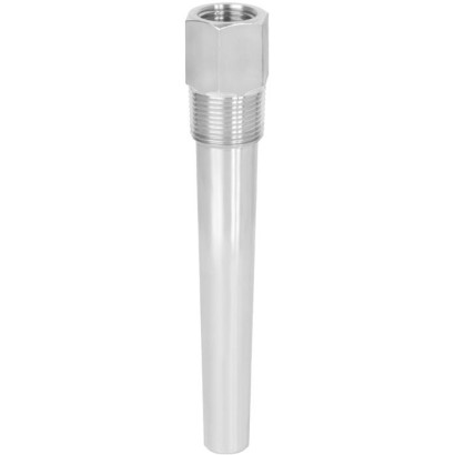
שרוול תרמי מוברג
תיאור
כל שרוול תרמי/צינור הגנה הוא רכיב חשוב בכל נקודת מדידת טמפרטורה. הוא משמש להפרדת התהליך מהסביבה, ובכך מגן על הסביבה ועל אנשי התפעול, ומונע ממדיות אגרסיביות, לחצים גבוהים וזרימות גבוהות לפגוע בגוף חיישן הטמפרטורה עצמו; בכך הוא מאפשר להחליף את המדחום במהלך העבודה.
בהתבסס על אפשרויות היישום כמעט בלתי מוגבלות, קיימים מספר רב של וריאנטים, כגון תכנוני שרוולים תרמיים או חומרי ייצור. סוג חיבור התהליך ושיטת הייצור הבסיסית הם קריטריוני בידול תכנוניים חשובים. בידול בסיסי ניתן לבצע בין שרוולים תרמיים/צינורות הגנה עם הברגה לבין כאלה המיועדים לריתוך, וכן בין אלה עם חיבורי אוגן.
תכונות מיוחדות
- תקן בינלאומי
- עיצובים אפשריים של בית מדחום: חרוטי, ישר או מדורג
שאלות ותשובות
מה מטרת שרוול הטבילה התרמי?
השרוול מפריד בין התהליך לסביבה, מגן על גוף חיישן הטמפרטורה מפני מדיות אגרסיביות, לחץ וזרימה גבוהים, ומאפשר החלפת המדחום בזמן פעולה.
אילו חיבורי תהליך זמינים ל-TW15?
קיימים חיבורים מוברגים בתקנים בינלאומיים, בהם ½ NPT male thread, ¾ NPT male thread, 1 NPT male thread, G ½ B, G ¾ B, M20 x 1.5, M27 x 2, ½ BSPT, ¾ BSPT, ½ BSPP ו-¾ BSPP.
מאילו חומרים ניתן לייצר את השרוול?
Stainless steel 316/316L, Stainless steel 304/304L, A105, Stainless steel 1.4571, Alloy C4, Alloy C276, Alloy 400, Titanium grade 2, וכן חומרים לפי תקני ASTM — מה שמאפשר התאמה לעומסים כימיים גבוהים.
אילו צורות שרוול זמינות?
ניתן להזמין את השרוול בעיצוב חרוטי (tapered), ישר (straight) או מדורג (stepped).
אילו תעודות איכות זמינות?
ניתן לקבל דו"ח בדיקה 2.2 או תעודת בדיקה 3.1.
מה מבדיל את TW15 מדגמים אחרים?
TW15 הוא שרוול תרמי מוברג עם עיצוב ראש של משושה, משטחי מפתח משופעים או עגול עם משושה, המיועד במיוחד לעומסים כימיים ולעומסי תהליך גבוהים בתעשייה הכימית והפטרוכימית.
מהו קוטר החדירה של השרוול?
קוטר החדירה הוא 6.6 מ"מ.
| דגם | TW15 |
| תת-קטגוריה | Threaded thermowell |
| חיבור תהליך | 1 NPT male threadM27 x 21 BSPWG ½ BM20 x 1.5½ NPT male thread¾ NPT male threadG ¾ B½ BSPT¾ BSPT½ BSPP¾ BSPPM20 x 1,51/2 NPT male thread3/4 NPT male threadG 1/2 female thread1/2 BSPT3/4 BSPT1/2 BSPP |
| חומר תרמופור | Stainless steel 316/316L, Stainless steel 304/304L, A105, Stainless steel 1.4571, Alloy C4, Alloy C276, Alloy 400, Titanium grade 2, Materials per ASTM specifications |
| משקל | 0.2 kg |
| תקנים | 2.2 test report3.1 inspection certificate |
| קוטר גשש | 6.6 mm |
| תרמופור | כן |
| צורת תרמופור | tapered, straight, stepped |
| שפות גיליון נתונים | EN |
| Thermowell form | ■ Tapered ■ Straight ■ Stepped |
|---|---|
| Version | |
| DesignTW15-H | Hexagon |
| DesignTW15-R | Milled wrench flats |
| DesignTW15-M | Round with hexagon |
| Material (wetted) | ■ Stainless steel 316/316L ■ Stainless steel 304/304L ■ A105 ■ Stainless steel 1.4571 ■ Alloy C4 ■ Alloy C276 ■ Alloy 400 ■ Titanium grade 2 ■ Materials per ASTM specifications → Other materials on request |
| Process connection | ||
|---|---|---|
| Type of process connection | ■ ½NPTmale thread ■ ¾NPTmale thread ■ 1 NPT male thread | |
| → Other threads on request | ||
| Connection to thermometer | ■ ½NPTfemale thread ■ G½female thread | |
| → Other threads on request | ||
| Bore size | ■ Ø6.6 mm[0.26 in] ■ Ø8.5 mm[0.36 in] | |
| → Other bore sizes on request | ||
| Insertion length U | ■ 50 mm[1.97] ■ 75 mm[2.95] ■ 100 mm[2.5 in] ■ 150 mm[5.9 in] ■ 200 mm[7.87 in] ■ 350 mm[13.78 in] ■ 400 mm[15.75 in] | ■ 6 in [152 mm] ■ 7 in [178 mm] ■ 10 in [254 mm] ■ 13 in [330 mm] ■ 16 in [406 mm] |
| → Weitere Einbaulängen auf Anfrage | ||
| Min. insertion length | Depending on the selected version | |
| Max. insertion length 1) | 800 mm[31.5 in] | |
| Connection length H | 45 mm[1.75 in] | |
| Min. Connection length | Depending on the selected version | |
| Max. Connection length | 250 mm[10 in] | |
| Tip thickness | 6.4 mm[0.25 in] | |
| → Other tip thicknesses on request | ||
| Suitable stem length l 1 (dial thermometer) | ||
| Connection design S, 4, 4.1, 5, 6.1, 6.2, 6.3 and 7 | Parallel thread | l 1 = U + H - 10 mm[0.4 in] |
| Tapered thread | l 1 = U + H - 2 mm[0.08 in] | |
| Connection design 2 | l 1 = U + H - 30 mm[1.2 in] |
| Max. process temperature, process pressure | Depending on: ■ Thermowell design - Dimensions - Material ■ Process conditions - Flow rate - Medium density |
|---|---|
| Wake frequency calculation | The calculation in accordance with ASME PTC 19.3 TW-2016 of individual thermowells minimises the risk of dynamic damage that can be caused by the vortex shedding of a Kármán vortex street (Vortex Induced Vibration; VIV). In addition, the static loads due to lateral flow and the process pressure are calculated depending on the temperature. The calculation can be carried out independently using an online tool or as aWIKA engineered service (subject to charges). → For further information seeTechnical information IN 00.15'Wake frequency calculation'. |
| Process connec- tion | Head design | Dimensions in mm[in] | Weight in kg [lbs] | ||||||||
|---|---|---|---|---|---|---|---|---|---|---|---|
| Hexagon or round with hexagon | Round with wrench flats | ||||||||||
| Metric | Imperial | Metric | Imperial | N | Ø Q | ØV | Ø B | H | U=2½in | U=7½in | |
| ½NPT | HEX 27 | HEX1.125 | Ø34mm with SW28 | Ø1.375 in with SW1⅛in | ■ ½NPT ■ G½ ■ M20 x 1,5 | 16 [0.625] | 13 [0.512] | ■ 6.6 [0.260] ■ 8.5 [0.355] | 45 [1.772] | 0.20 [0.441] | 0.36 [0.794] |
| ¾NPT | HEX 27 | HEX1.125 | ■ ½NPT ■ G½ ■ M20 x 1,5 | 22 [0.866] | 16 [0.625] | ■ 6.6 [0.260] ■ 8.5 [0.355] | 45 [1.772] | 0.31 [0.683] | 0.56 [1.235] | ||
| 1 NPT | HEX 36 | HEX1.375 | ■ ½NPT ■ G½ ■ M20 x 1,5 | 27 [1.063] | 19 [0.750] | ■ 6.6 [0.260] ■ 8.5 [0.355] | 45 [1.772] | 0.50 [1.102] | 0.84 [1.852] | ||
| G ½ B | HEX 27 | HEX1,125 | - | - | ■ ½NPT ■ G½ ■ M20 x 1,5 | 16 [0.625] | 13 [0.512] | ■ 6.6 [0.260] ■ 8.5 [0.355] | 45 [1.772] | 0.20 [0.441] | 0.36 [0.794] |
| G¾B | HEX 32 | HEX1,259 | - | - | ■ ½NPT ■ G½ ■ M20 x 1,5 | 22 [0.866] | 16 [0.625] | ■ 6.6 [0.260] ■ 8.5 [0.355] | 45 [1.772] | 0,35 [0.772] | 0,6 [1.323] |
| M20 x 1,5 | HEX 27 | HEX1,125 | - | - | ■ ½NPT ■ G½ ■ M20 x 1,5 | 16 [0.625] | 13 [0.512] | ■ 6.6 [0.260] ■ 8.5 [0.355] | 45 [1.772] | 0,20 [0.441] | 0,36 [0.794] |
| M27 x 2 | HEX 32 | HEX1,259 | - | - | ■ ½NPT ■ G½ ■ M20 x 1,5 | 22 [0.866] | 16 [0.625] | ■ 6.6 [0.260] ■ 8.5 [0.355] | 45 [1.772] | 0,35 [0.772] | 0,6 [1.323] |
| ½BSPT | HEX 27 | HEX1,125 | - | - | ■ ½NPT ■ G½ ■ M20 x 1,5 | 16 [0.625] | 13 [0.512] | ■ 6.6 [0.260] ■ 8.5 [0.355] | 45 [1.772] | 0,20 [0.441] | 0,36 [0.794] |
| ¾BSPT | HEX 32 | HEX1,259 | - | - | ■ ½NPT ■ G½ ■ M20 x 1,5 | 22 [0.866] | 16 [0.625] | ■ 6.6 [0.260] ■ 8.5 [0.355] | 45 [1.772] | 0,35 [0.772] | 0,6 [1.323] |
| 1 BSPW | HEX 36 | HEX1,375 | - | - | ■ ½NPT ■ G½ ■ M20 x 1,5 | 27 [1.063] | 19 [0.750] | ■ 6.6 [0.260] ■ 8.5 [0.355] | 45 [1.772] | 0,50 [1.102] | 0,84 [1.852] |
| ½BSPP | HEX 27 | HEX1,125 | - | - | ■ ½NPT ■ G½ ■ M20 x 1,5 | 16 [0.625] | 13 [0.512] | ■ 6.6 [0.260] ■ 8.5 [0.355] | 45 [1.772] | 0,20 [0.441] | 0,36 [0.794] |
| ¾BSPP | HEX 36 | HEX1,375 | - | - | ■ ½NPT ■ G½ ■ M20 x 1,5 | 22 [0.866] | 16 [0.625] | ■ 6.6 [0.260] ■ 8.5 [0.355] | 45 [1.772] | 0,50 [1.102] | 0,84 [1.852] |
לא מצאתם תשובה בתיעוד? מהנדס יענה במהלך יום עסקים.
שאלו מהנדס →1 מק״טים סטנדרטיים של משפחת TW15
אם ידוע הקוד — בחרו ישירות. אם לא — השתמשו בתצורה במצב «01».