
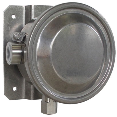
מתג לחץ עם צינור בורדון
תיאור
מתגי הלחץ האיכותיים הללו פותחו במיוחד עבור יישומים בעלי חשיבות בטיחותית קריטית. האיכות הגבוהה של המוצרים והייצור בהתאם ל-ISO 9001 מבטיחים ניטור אמין של המפעל שלך. במהלך הייצור, המתגים עוברים עקיבה באמצעות תוכנת בקרת איכות בכל שלב ולאחר מכן נבדקים ב-100 %. כל חומרי המגע עם התווך הם, כברירת מחדל, מפלדת אל-חלד.
כדי להבטיח פעולה גמישה ככל האפשר, מתגי הלחץ מצוידים במיקרו-מתגים (microswitches), המאפשרים מיתוג של עומס חשמלי עד AC 250 V, 20 A ישירות. עבור הספקי מיתוג נמוכים יותר, כגון עבור יישומי PLC, ניתן לבחור במיקרו-מתגים אטומי ארגון (argon gas-filled) עם מגעים מצופים זהב.
לאישורים נוספים, ראה עמוד 5
תכונות מיוחדות
- תיבת מפסק עמידה מ-316L, IP66, NEMA 4X
- טווחי הגדרה מ- 0 ... 2.5 bar ועד 0 ... 1,000 bar, טווחי ואקום
- בטיחות פנימית Ex ia זמינה
- חזרתיות נקודת המיתוג < 0.5 %
- נקודת מיתוג אחת או שתיים בלתי תלויות, הספק מיתוג גבוה עד AC 250 V, 20 A, ללא צורך במתח אספקה
שאלות ותשובות
מהו טווח הלחץ של ה-BWX?
הטווחים נעים מ-0 … 2.5 bar ועד 0 … 1,000 bar, ובנוסף טווחי ואקום מ- -1.0 … 1.5 bar ועד -1.0 … 15.0 bar.
מהי הדיוק של מתג הלחץ?
מחלקת הדיוק היא ≤ 0.5 % of span, בהתאם לתקן IEC 61298-2:2008. חזרתיות נקודת המיתוג היא < 0.5 %.
מהם אפשרויות חיבור התהליך?
החיבורים כוללים בין השאר ¼NPT, female thread, ½NPT, female thread via adapter, ½NPT, male thread via adapter, G¼, female thread via adapter, G½A, male thread via adapter ו-G¼A, male thread via adapter.
אילו חומרי חלקים במגע עם התווך זמינים?
Stainless steel AISI 316L, 17-4PH® (1.4542), Monel® 400 ו-Inconel 718 (2.4668) — מה שמאפשר שימוש גם עם תווכים תוקפניים.
מהם טווחי הטמפרטורה?
טמפרטורת הסביבה: -60 … +85 °C. טמפרטורת התווך: -40 … +85 °C.
האם יש אישור לאזורים מסוכנים?
כן — בטיחות מהותית Ex ia עם אישורי ATEX ו-IECEx, לרבות Ex ia IIC T6/T4 Ga, Ex ia IIIC T85°C/T135°C Da IP66 ו-Ex ia I Ma. המתג מוסמג גם SIL 2-qualified ו-SIL 3-qualified.
מה מבדיל את ה-BWX מדגמים סמוכים?
הוא מיועד במיוחד ליישומים בעלי חשיבות בטיחותית קריטית: בית נירוסתה 316L עם IP66/NEMA 4X, מיתוג ישיר של עומס עד AC 250 V, 20 A ללא מתח אספקה, ואפשרות לשתי נקודות מיתוג בלתי תלויות.
| דגם | BWX |
| תת-קטגוריה | Pressure Switch |
| טווח לחץ | -1…1.5 bar · -1…5 bar · -1…15 bar · 0…2.5 bar · 0…6 bar · 0…16 bar · 0…40 bar · 0…100 bar · 0…160 bar · 0…250 bar · 0…400 bar · 0…600 bar · 0…1000 bar |
| מחלקת דיוק | ≤ 0.5 % of span |
| תקן דיוק | IEC 61298-2:2008 |
| רמת בטיחות תפקודית (SIL) | SIL 2-qualified, SIL 3-qualified |
| חיבור תהליך | ¼NPT, female thread½NPT, female thread via adapter½NPT, male thread via adapterG¼, female thread via adapterG½A, male thread via adapterG¼A, male thread via adapter1/4 NPT, female thread1/2 NPT, female thread via adapter1/2 NPT, male thread via adapterG 1/4, female thread via adapterG 1/2 A, male thread via adapterG 1/4 A, male thread via adapter |
| טמפ׳ תהליך | −40…+85 °C |
| חיבור חשמלי | ½NPT female thread, M20 x 1.5 female thread, ¾NPT, G½, G¾, M20 x 1.5, cable gland non-armoured nickel-plated brass, cable gland non-armoured stainless steel (AISI 304), cable gland armoured nickel-plated brass, cable gland armoured stainless steel (AISI 304), MIL connector 7-pin DTL 5015 |
| פונקציית מתג | 1 x SPDT, 2 x SPDT, 1 x DPDT |
| מגעי מתג | 2 |
| חומר מארז | Stainless steel 316L |
| חומר חלקים רטובים | Stainless steel AISI 316L, Stainless steel 17-4PH (1.4542), Monel 400, 17-4PH® (1.4542), Monel® 400, Inconel 718 (2.4668) |
| טמפ׳ סביבה | −60…+85 °C |
| דרגת הגנה IP | IP66 |
| משקל | 2 kg |
| תקנים | RoHSUKCAEACPEDATEXIECExCCCKCECASCE |
| הגנת התפוצצות | Ex ia I MaEx ia IIIC T85°C/T135°C Da IP66Ex ia IIC T6/T4Ex ia IIC T6/T4 Ga |
| שפות גיליון נתונים | EN |
| Basic information | |
|---|---|
| Version | Bourdon tube pressure switch |
| Special design feature | ■ Version for hazardous areas (Ex ia) ■ For oxygen, oil- and grease-free ■ Per NACE 1) MR0175 / ISO 15156, use in H₂S-containing environments in oil and gas production ■ Per NACE 1) MR0103 / ISO 17945, metals resistant to sulphide stress cracking ■ Version for hydrogen (H 2 ) applications ■ Drying of wetted parts ■ Offshore version ■ Tropical version (suitable for environments with increased air humidity) ■ Version for ammonia applications ■ Geothermal version ■ Low-temperature version to -60 °C ■ Assembled as a diaphragm seal system |
| Contact version | →See table 'Contact version' |
| Function | ■ 1 x SPDT (single pole double throw) ■ 2 x SPDT (single pole double throw) ■ 1 x DPDT (double pole double throw) The DPDT function is realised with 2 simultaneously triggering SPDT microswitches, within 0.2 %of span. |
| Dead band | ■ 1 or 2 contacts with fixed dead band ■ 1 or 2 contacts with adjustable dead band ■ 1 contact with fixed dead band and 1 contact with adjustable dead band |
| Dielectric strength | Safety class I (IEC 61298-2: 2008) |
| Switch enclosure | |
| Design | Case cover with bayonet lock, protection against unauthorised access by lead sealing possible. Laser-engraved product label from stainless steel. |
| Material | Stainless steel 316L |
| Mounting 2) | ■ Direct mounting ■ Wall bracket from stainless steel AISI 304 ■ Mounting bracket for 2" pipe mounting from stainless steel AISI 304 |
| Contact version | Electrical rating (resistive load) | Suitable for Ex ia option | ||
|---|---|---|---|---|
| AC | DC | |||
| With fixed dead band | ||||
| UN | 1 x SPDT, silver | 250 V, 15 A | 24 V, 2 A, 125 V, 0.5 A, 220 V, 0.25 A | No |
| US | 1 x SPDT, silver, hermetically sealed, argon gas filling 1) | 250 V, 15 A | 24 V, 2 A, 220 V, 0.5 A | Yes |
| UO | 1 x SPDT, gold-plated, hermetically sealed, argon gas filling 1) | 125 V, 1 A | 24 V, 0.5 A | Yes |
| UG | 1 x SPDT, gold-plated | 125 V, 1 A | 24 V, 0.5 A | Yes |
| DN | 2 x SPDT or 1 x DPDT, silver | 250 V, 15 A | 24 V, 2 A, 125 V, 0.5 A, 220 V, 0.25 A | No |
| DS | 2 x SPDT or 1 x DPDT, silver, hermetically sealed, argon gas filling 1) | 250 V, 15 A | 24 V, 2 A, 220 V, 0.5 A | Yes |
| DO | 2 x SPDT, or 1 x DPDT gold-plated, hermetically sealed, argon gas filling 1) | 125 V, 1 A | 24 V, 0.5 A | Yes |
| DG | 2 x SPDT or 1 x DPDT, gold-plated | 125 V, 1 A | 24 V, 0.5 A | Yes |
| With adjustable dead band | ||||
| UR | 1 x SPDT, silver | 250 V, 20 A | 24 V, 2 A, 220 V, 0.5 A | Yes 2) |
| RR 3) | 2 x SPDT or 1 x DPDT, silver | 250 V, 15 A | 24 V, 2 A, 220 V, 0.5 A | Yes 2) |
| Set point repeatability | ≤ 0.5 %of span of setting range |
|---|---|
| Dead band | →See table 'Setting range' |
| Setting range (=working range) | Proof pressure | Fixed dead band | Adjustable dead band | |
|---|---|---|---|---|
| in bar | in bar | 1 contact UN, US, UO, UG in bar | 2 contacts DN, DS, DO, DG in bar | 1 contact UR in bar |
| -1 ... +1.5 | 4.5 | ≤ 0.15 | ≤ 0.30 | 0.35 ... 1.10 |
| -1 ... +5 | 12 | ≤ 0.20 | ≤ 0.30 | 0.55 ... 1.70 |
| -1 ... +15 | 30 | ≤ 0.30 | ≤ 0.40 | 1.40 ... 3.10 |
| 0 ... 2.5 | 4.5 | ≤ 0.15 | ≤ 0.30 | 0.35 ... 1.10 |
| 0 ... 6 | 12 | ≤ 0.20 | ≤ 0.30 | 0.55 ... 1.70 |
| 0 ... 16 | 30 | ≤ 0.30 | ≤ 0.40 | 1.40 ... 3.10 |
| 0 ... 40 | 75 | ≤ 0.60 | ≤ 0.70 | 2.10 ... 6.00 |
| 0 ... 100 | 160 | ≤ 2 | ≤ 2 | 6 ... 17 |
| 0 ... 160 | 210 | ≤ 3 | ≤ 3 | 13 ... 35 |
| 0 ... 250 | 330 | ≤ 5 | ≤ 5 | 21 ... 65 |
| 0 ... 400 | 480 | ≤ 8 | ≤ 8 | 26 ... 93 |
| 0 ... 600 | 720 | ≤ 12 | ≤ 12 | 40 ... 115 |
| 0 ... 1,000 1) | 1,200 | ≤ 20 | ≤ 30 | 75 ... 190 |
הצגת הכול (14)
| Process connection | |
|---|---|
| Standard | ■ ANSI/ASME B1.20.1 ■ DIN EN ISO 228 |
| Size | |
| ANSI/ASME B1.20.1 | ■ ¼NPT, female thread ■ ½NPT, female thread via adapter ■ ½NPT, male thread via adapter |
| DIN EN ISO 228 | ■ G¼, female thread via adapter ■ G½A,male thread via adapter ■ G¼A,male thread via adapter |
| Material (wetted) | |
| Sensor element | Depending on the selected version |
| Process connection | →See table 'Wetted parts' |
| Version | Bourdon tube | Process connection |
|---|---|---|
| Standard | Stainless steel AISI 316L | |
| Setting range: 0 ... 1,000 bar | Stainless steel 17-4PH (1.4542) | Stainless steel AISI 316L |
| NACE Setting range: 0 ... 40 to 0 ... 400 bar | Monel 400 | Stainless steel AISI 316L |
| Monel Setting range: 0 ... 40 to 0 ... 400 bar | Monel 400 |
| Connection type | ■ Female thread½NPT ■ Female thread M20 x 1.5 ■ Female thread ¾NPT, G½, G¾, M20 x 1.5 ■ Cable gland non-armoured, nickel-plated brass ■ Cable gland non-armoured, stainless steel (AISI 304) ■ Cable gland armoured, nickel-plated brass ■ Cable gland armoured, stainless steel (AISI 304) ■ MIL connector, 7-pin, DTL 5015 |
|---|---|
| Wire cross-section | Use 0.5 ... 1.5 mm² (20 ... 16 AWG) for internal terminal block (also suitable for cable lugs). For the grounding cable connection to the protective conductor use max. 4 mm² for the internal and external screw. |
| Pin assignment | Connection details are given on the product label of the instrument. Connection terminals and the ground terminal are appropriately marked. |
| Medium temperature range | -40 ...+85 °C |
|---|---|
| Ambient temperature range | T6/T85°C T a -60 ...+60 |
| T4/T135°C T a -60 ...+85 | |
| Non-Ex versions ■ -40 ...+85 °C | |
| Ingress protection of the complete instrument | IP66 per EN/IEC 60529 (NEMA 4X) |
| Weight | Approx. 2.0 kg |
| Logo | Description | Region |
|---|---|---|
| EU declaration of conformity | European Union | |
| Pressure equipment directive PED, annex 1, category IV, safety accessories, module B + D | ||
| Low voltage directive | ||
| RoHS directive |
| Logo | Description | Region |
|---|---|---|
| EU declaration of conformity | European Union | |
| ATEX directive 1) IM1 II1GD | ||
| IECEx 1) Ex ia I Ma Ex ia IIC T6/T4 2) Ga Ex ia IIIC T85°C/T135°C 2) Da IP66 | International | |
| UKCA | United Kingdom | |
| Pressure equipment (safety) regulations | ||
| Electrical equipment designed for use within certain voltage limits in support of the electrical equipment (safety) regulations | ||
| Restriction of hazardous substances (RoHS) regulations | ||
| Equipment and protective systems intended for use in potentially explosive atmospheres regulations 1) | ||
| EAC | Eurasian Economic Community | |
| Low voltage directive (applies only for non-Ex versions) | ||
| Hazardous areas 1) | ||
| Ex Ukraine Hazardous areas 1) | Ukraine | |
| CCC Hazardous areas 1) | China | |
| KCs Hazardous areas 1) | South Korea | |
| - | ECAS Hazardous areas 1) | United Arab Emirates |
| Logo | Description |
|---|---|
| SIL3 IEC 61508 / IEC 61511 | SIL 3-capable (option) Functional safety per IEC 61508 Contains performance level calculation per ISO 13849-1 |
| Certificates | ■ 2.2 test report per EN 10204 (e.g. state-of-the-art manufacturing, indication accuracy) ■ 3.1 inspection certificate per EN 10204 (e.g. indication accuracy) |
|---|---|
| Recommended calibration interval | 1 year (dependent on conditions of use) |
| Voltage | Ui = DC 30V |
|---|---|
| Current | Ii = 100mA |
| Power | P i = 750mW |
| Effective internal capacitance | Ci = 0 μF |
| Effective internal inductance | Li=0mH |
| Model | Description | |
|---|---|---|
| 910.15 | Syphons →See data sheet AC 09.06 | |
| 910.13 | Overpressure protector →See data sheet AC 09.04 | |
| IV10, IV11 | Needle valve and multiport valve →See data sheet AC 09.22 | |
| IV20, IV21 | Block-and-bleed valve →See data sheet AC 09.19 | |
| IVM | Monoflange, process and instrument version →See data sheet AC 09.17 | |
| BV | Ball valve, process and instrument version →See data sheet AC 09.28 |
לא מצאתם תשובה בתיעוד? מהנדס יענה במהלך יום עסקים.
שאלו מהנדס →