
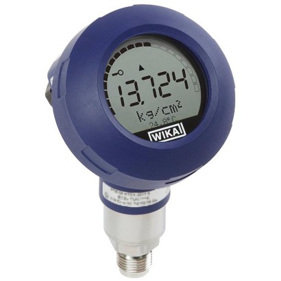
WIKA · Pressure measurement · Family UPT
Process transmitter
With pressure port or flush diaphragm
Range
-1…4000 bar
Output
4-20 mA · 4-20 mA with HART
Accuracy
0.15 % of span
Protection
IP65
CEEACRoHSREACHNACEATEXIECExFMCSA
Price
On request
Depends on configuration
Special features
- Multi-functional display
- Simple menu navigation
- Conductive plastic case or stainless steel case (optionally with electropolished surface)
- Large LC display, rotatable
- Approvals for hazardous areas
Configurator · Step by step
Build a UPT for your task
The article number is assembled automatically. If unsure — ask an engineer; we'll match the line's parameters.
Step 1 of 1
Your configuration
- Process connection typeStandard connection with pressure port
- Electrical approvalWithout
- Ignition protection typeWithout
- ZoneWithout
- Case designplastic version, IP66/IP67
- Digital Displaywith integrated 4 1/2 digit LCD-display
- Output signal4 ... 20 mA, 2-wire
- Electrical connectionM20x1,5 / cable gland PA black (ø6-12mm)
- Unitbar
- Pressure typegauge
- Measuring range0 ... 0.4 bar gauge
- Process connection—
- Sealingwithout
- Wetted partsstainless steel
- Accuracy0.15% of span
- Special design featureswithout
- Certificates/Approvalswithout
- Additional ordering informationWithout
AI suggestion by parameters
Finish your configuration
Select every option to submit the request.
Identification
| Model | UPT-20 |
| Product family | UPT |
| Subcategory | Process transmitter |
Measuring range
| Pressure ranges | 0…1.6 bar · 0…6 bar · 0…16 bar · 0…40 bar · 0…0.4 bar · 0…100 bar · 0…250 bar · 0…600 bar · 0…1000 bar · 0…1600 bar · 0…2500 bar · 0…4000 bar · 0…10 psi · 0…15 psi · 0…30 psi · 0…100 psi · 0…300 psi · 0…500 psi · 0…1500 psi · 0…5000 psi · 0…10000 psi · 0…15000 psi · 0…30000 psi · 0…50000 psi · 0…60000 psi · -1…0 bar · -0.2…0.2 bar · -1…0.6 bar · -1…5 bar · -1…15 bar · -1…40 bar · -14.5…0 psi · -14.5…15 psi · -14.5…100 psi · -14.5…300 psi · -14.5…600 psi |
Accuracy
| Accuracy class | 0.15 % of span |
| Accuracy standard | IEC 61298-2 |
Process conditions
| Process connection | G 1/2 BG 1 BG 1 1/2 B1/2 NPT1 NPT1 1/2 NPT |
| Process temperature | −40…+150 °C |
Electrical characteristics
| Output signal | 4-20 mA · 4-20 mA with HART |
| Power supply | 10...30 V DC |
| Electrical connection | M12 4-pin, cable gland, terminal block |
Materials
| Case material | Conductive plastic, Stainless steel 316L |
| Wetted parts material | Stainless steel 316L, Elgiloy |
| Sealing material | FKM, EPDM, FPM, Metal |
Operating environment
| Ambient temperature | −40…+85 °C |
| IP rating | IP65 |
| Weight | 1.2 kg |
Certifications and approvals
| Certifications | CEEACRoHSREACHNACE |
| Explosion protection | ATEXIECExFMCSA |
Additional details
| Datasheet languages | EN, DE |
Tables from datasheet
Gauge pressure
| bar | 0 ... 0.4 | 0 ... 1.6 | 0 ... 6 | 0 ... 16 | 0 ... 40 | 0 ... 100 |
|---|---|---|---|---|---|---|
| 0 ... 250 | 0 ... 600 | 0 ... 1,000 | 0 ... 1,600 | 0 ... 2,500 | 0 ... 4,000 | |
| psi | 0 ... 10 | 0 ... 15 | 0 ... 30 | 0 ... 100 | 0 ... 300 | 0 ... 500 |
| 0 ... 1,500 | 0 .... 5,000 | 0 ... 10,000 | 0 ... 15,000 | 0 ... 30,000 | 0 ... 50,000 | |
| 0 ... 60,000 | ||||||
| Absolute pressure | ||||||
| bar | 0 ... 1.6 | 0 ... 6 | 0 ... 16 | 0 ... 40 | ||
| psi | 0 ... 30 | 0 ... 100 | 0 ... 300 | 0 ... 500 | ||
| Vacuum and +/- measuring ranges | ||||||
| bar | -1 ... 0 | -0.2 ... +0.2 | -1 ... +0.6 | -1 ...+5 | -1 ...+15 | -1 ...+40 |
| psi | -14.5 ... 0 | -14.5 ...+15 | -14.5 ...+100 | -14.5 ...+300 | -14.5 ...+600 |
Vacuum/overload safety
| Vacuum safety | Yes (not for oxygen applications) |
|---|---|
| Overload safety (standard version, version with cooling element) | |
| Measuring range ≤ 40 bar [500 psi] | 3 times |
| Measuring range 40 ... 1,000 bar [500 .... 15,000 psi] | 2 times |
| Measuring range 1,600 bar [30,000 psi] | 1.5 times |
| Measuring range 2,500 bar [50,000 psi] | 1.4 times |
| Measuring range 4,000 bar [60,000 psi] | 1.25 times |
Output signals
| Signal types | ■ 4 ...20mA ■ 4 ... 20 mAwith HART ® signal (option) |
|---|---|
| Load in Ω | ■ ≤ U + - 12V / 0.023 A (non-Ex) ■ ≤ U + - 14V / 0.023 A (Ex) |
| U + = Applied supply voltage (→ see 'Supply voltage') | |
| Dampening | 0 ... 99.9 s, adjustable |
| After the set dampening time the instrument outputs 63 %of the applied pressure as output signal. | |
| Settling time t 90 | |
| Without HART ® | 60 ms |
| With HART ® | 80 ms |
| Refresh rate | |
| Without HART ® | 20 ms |
| With HART ® | 50 ms |
Accuracy specifications
| Accuracy at reference conditions 1) | ■ 0.15 %of span ■ 0.1 %of span (option 1) ■ 0.2 %of span (option 2) ■ 0.5 %of span (> 1,000 bar [15,000 psi]) (option 3) | ||
|---|---|---|---|
| Adjustability | |||
| Zero point | -20 ...+95 %(downwards, the adjustability is always limited by the minimum pressure of 0 bar abs. [0 psia]) | ||
| Span | Measuring range ≤ 1,000 bar [15,000 psi] | -120 ...+120 %with a difference between zero point and span of max. 120 %of the nominal measuring range | |
| Measuring range > 1,000 bar [15,000 psi] | Max. (0 bar abs. [0 psia]) ...+105 %(down- wards, the adjustability is always limited by the minimum pressure of 0 bar abs. [0 psia]) | ||
| Turndown ratio | Unlimited | ||
| Measuring range ≤ 1,000 bar [15,000 psi] Measuring range > 1,000 bar [15,000 psi] | Maximum recommended turndown 20:1 Maximum recommended turndown 2:1 | ||
| Mounting correction | -20 ...+20% | ||
| Non-repeatability | |||
| Measuring ranges ≤ 1,000 bar [15,000 psi] | ≤ 0.1 %of span | ||
| Measuring ranges > 1,000 bar [15,000 psi] | ≤ 0.5 %of span | ||
| Behaviour with turndown 2) | |||
| Measuring ranges from 0 ...1.6 bar to 0 ... 1,000 bar [0 ...25 psi to 0 ... 15,000 psi] | TD ≤ 5:1 TD > 5:1 ...≤ 100:1 | No influence on the accuracy | |
| Measuring range < 1.6 bar [30 psi] | TD = 1:1 TD > 1:1 ...≤ 100:1 | No influence on the accuracy | 4) / 5 |
| Measuring range >1,000 bar [15,000 psi] | ≤ 0.5 xTD | ||
| Long-term stability | |||
| Measuring range < 1 bar [14.5 psi] | 0.35 %/year | ||
| Measuring range ≥ 1 bar [14.5 psi] | 0.15 %/year | ||
| Measuring range ≥ 1.6 bar [30 psi] | 0.1 %/year | ||
| Measuring range ≥ 40 bar [600 psi] | 0.1 %/year | ||
| range > 1,000 bar [15,000 psi] | ≤ 0.5 %/year | Measuring | |
| Thermal change, zero point / span (reference temperature 20 °C [68 °F]) | |||
| In the temperature-compensated range 10 ... 70 °C [50 ... 158 °F] | No additional temperature error (only applies to measuring range up to 1,000 bar [15,000 psi]) | ||
| Outside compensated range | Typical < 0.1 %/10 K (for >1,000 bar [15,000 psi]: 0.2 %/10 K) | ||
| Thermal change of the current output (reference temperature 20 °C [68 °F]) | |||
| < 18 °C and > 28 °C [< 64 °F and > 82 °F] | 0.1 %/10 K (max. 0.15 %/10 K) |
View all (20)
Reference conditions (per IEC 61298-1)
| Temperature | 23 °C ±2 °C [73 °F ±7 °F] |
|---|---|
| Supply voltage | DC 23 ...25V |
| Air pressure | 860 ... 1,060 mbar [86 ... 106 kPa, 12.5 ... 15.4 psi] |
| Air humidity | 45 ... 75 %r.h. |
| Characteristic curve determination | Terminal method per IEC 61298-2 |
| Curve characteristics | Linear |
| Reference mounting position | Vertical, diaphragm points downward |
Voltage supply
| Voltage supply (non-Ex) | |
|---|---|
| Supply voltage U + | DC 12 ...36V |
| Voltage supply (Ex) | |
| Supply voltage U + | DC 14 ...30V |
| Maximum voltage U i | DC 30V |
| Maximum current I i | 100mA |
| Maximum power P i (gas) | 1,000mW |
| Maximum power P i (dust) | 750/650/550 mW(depending on the max. ambient temperature) |
| Effective internal capacitance | 11 nF |
| Effective internal inductance | 100 μH |
| Per standard | Thread size | Possible measuring ranges |
|---|---|---|
| EN 837 | G⅜B | ≤ 0 ... 1,000 bar [0 ... 15,000 psi] |
| G½B | ≤ 0 ... 1,000 bar [0 ... 15,000 psi] | |
| M20 x 1.5 | ≤ 0 ... 1,000 bar [0 ... 15,000 psi] | |
| ANSI / ASME B1.20.1 | ½NPT | ≤ 0 ... 1,000 bar [0 ... 15,000 psi] |
| ½NPT, female | ≤ 0 ... 1,000 bar [0 ... 15,000 psi] | |
| ¼NPT | ≤ 0 ... 1,000 bar [0 ... 15,000 psi] | |
| - | M16 x 1.5 mmfemale with sealing cone | ≥ 0 ... 100 bar [0 ... 1,500 psi] |
| M20 x 1.5 mmfemale with sealing cone | ≥ 0 ... 1,600 bar [0 ... 23,200 psi] | |
| 9/16-18 UNF female F 250-C | ≥ 0 ... 100 bar [0 ... 1,500 psi] | |
| 1 1/8 -12 UNF female F 562-C | ≥ 0 ... 100 bar [0 ... 1,500 psi] |
| Per standard | Thread size | Possible measuring ranges |
|---|---|---|
| - | G½B | 0 ...6 to 0 ...600 bar [0 ...100 to 0 ... 5,000 psi] |
| G1B | ≤ 0 ... 1.6 bar [0 ... 30 psi] | |
| G1½B | ≤ 0 ... 1.6 bar [0 ... 30 psi] | |
| G1hygienic 1) 2) | ≤ 0 ... 16 bar [0 ... 100 psi] | |
| G1hygienic with cooling element 2) | ≤ 0 ... 16 bar [0 ... 100 psi] | |
| M44 x 1.25 with union nut | ≤ 0 ... 40 bar [0 ... 500 psi] | |
| TRI-CLAMP ® | DN 1½ with cooling element for 150 °C [302 °F] | ≤ 0 ... 40 bar [0 ... 500 psi] 4) |
| DN 2 with cooling element for 150 °C [302 °F] | ≤ 0 ... 40 bar [0 ... 500 psi] 4) | |
| Clamp DIN 32676 | DN 40 with cooling element for 150 °C [302 °F] | ≤ 0 ... 40 bar [0 ... 500 psi] 4) |
| DN 50 with cooling element for 150 °C [302 °F] | ≤ 0 ... 40 bar [0 ... 500 psi] 4) | |
| Grooved union nut DIN 11851 with conical coupling 3) | DN 25 with cooling element for 150 °C [302 °F] | ≤ 0 ... 40 bar [0 ... 500 psi] |
| DN 50 with cooling element for 150 °C [302 °F] | ≤ 0 ... 25 bar [0 ... 500 psi] | |
| NEUMO BioConnect ® | DN 40 formV with cooling element for 150 °C [302 °F] | ≤ 0 ... 16 bar [0 ... 500 psi] |
| VARINLINE ® | Form N with cooling element for 150 °C [302 °F] DN 40 ... 50 | ≤ 0 ... 16 bar [0 ... 500 psi] |
| Form F with cooling element for 150 °C [302 °F] DN 25 | ≤ 0 ... 16 bar [0 ... 500 psi] |
| Model | Medium |
|---|---|
| Model UPT-20 | Measuring range ≤ 40 bar [500 psi]: Synthetic oil (halocarbon oil for oxygen applications) Measuring range > 40 bar [500 psi]: Dry measuring cell |
| Model UPT-21 | Synthetic oil |
| Model | Measuring ranges | Process connections | Materials | |
|---|---|---|---|---|
| Materials (wetted) | ||||
| UPT-20 | ≤ 40 bar [500 psi] | All | Standard | Process connection: Stainless steel 1.4404 / 316L Sensor: Stainless steel 1.4404 / 316L |
| > 40 bar [500 psi] | All | Standard | Process connection: Stainless steel 1.4404 / 316L Sensor: Elgiloy ® 2.4711 | |
| > 1,000 bar [15,000 psi] | All | Standard | Process connection: Stainless steel 1.4534 / 904L Sensor: Stainless steel 1.4534 / 904L | |
| UPT-21 | All | All | Standard | Process connection: Stainless steel 1.4435 / 316L Diaphragm: Stainless steel 1.4435 / 316L |
| ■ G½ ■ G1 | Option 1 | Process connection: Hastelloy ® HC276 / 2.4819 Diaphragm: Hastelloy HC276 / 2.4819 | ||
| ■ G½ ■ G1 | Option 2 | Process connection: Gold-plated Diaphragm: Gold-plated 1) |
Case
| Option 1 | Plastic (PBT) with conductive surface per EN 60079-0:2012 Colour: Night blue RAL5022 |
|---|---|
| Option 2 | Stainless steel case 1.4308 (CF-8), precision cast (suitable for chemical and petrochemical industries) |
| Option 3 | Stainless steel case 1.4308 (CF-8) with electropolished surface (suitable for pharmaceutical, food and hygienic industries) |
| Option 4 1) | Stainless steel case coated with epoxy resin |
| Option 5 1) | Stainless steel case, electropolished and coated with epoxy resin |
Electrical connection
| Spring-loaded terminals | Wire cross-section: Wire or strand: 0.2 ... 2.5 mm² (AWG 24 ... 14) Strand with end splice: 0.2 ... 1.5 mm² (AWG 24 ... 16) | |
|---|---|---|
| Cable glands M20 x 1.5 | ||
| Plastic, PA | Sealing | NBR |
| Cable diameter | 6 ... 12 mm[0.24 ... 0.47 in] | |
| Ingress protection per IEC 60529 | IP66/67 | |
| Brass, nickel-plated | Sealing | NBR |
| Cable diameter | 5 ... 9 mm[0.2 ... 0.35 in] | |
| Ingress protection per IEC 60529 | IP66/67 | |
| Stainless steel cable gland | Sealing | NBR |
| Cable diameter | 7 ... 12 mm[0.28 ... 0.47 in] | |
| Ingress protection per IEC 60529 | IP66/67 | |
| Stainless steel cable gland in hygienic design | Sealing | FDA-compliant |
| Cable diameter | 6 ... 12 mm[0.24 ... 0.47 in] | |
| Ingress protection per IEC 60529 | IP66/67 | |
| Angular connector DIN 175301-803A with mating connector | Wire cross-section | Max.1.5mm 2 (AWG 16) |
| Ingress protection per IEC 60529 | IP65 1) | |
| Circular connector M12 x 1 (4-pin) without mating connector | Ingress protection per IEC 60529 | IP65 1) |
| Electrical safety | Reverse polarity protection |
Display and operating unit, model DI-PT-U (option)
| Display type | LC display 1) |
|---|---|
| Refresh rate | 200 ms |
| Main display | 4 ½-digit |
| Segment display | Character size 14 mm[0.55 in] |
| Additional display | Selectable via menu, three-line scale range |
| Bar graph display | 20 segments, radial, pressure gauge simulation |
| Adjustable units | |
| Pressure units | ■ bar ■ psi ■ mbar ■ MPa ■ kPa ■ hPa ■ Pa ■ mH₂O ■ ftH₂O ■ inH₂O ■ mHg ■ mmHg ■ inHg ■ kg/cm 2 ■ g/cm 2 ■ Torr |
| Level units | ■ m ■ cm ■ mm ■ ft ■ in |
| Volume units | ■ l ■ m 3 ■ gal ■ inch 3 ■ ft 3 ■ % |
| Free unit | A free character string (6 characters) can be defined as a unit |
| Operating state | Display via symbols |
| Operating temperature | By using the display and operating unit, the operating temperature is limited to -20 ...+60 °C [-4 ...+140 °F] |
| Storage temperature | -40 ...+80 °C [-40 ...+176 °F] |
| Operation | 4 buttons for the recall and operation of the settings |
| Colours | |
| Background | Light grey |
| Digits | Black |
| Upgradable | Yes (→ see 'Accessories') |
| Display size | Separated into main and segment displays |
| Ingress protection per IEC 60529 | ■ IP20 (loose) ■ IP40 (built-in without cover) |
| Material | Case from ABS, window from polyester film |
Operating conditions
| Range of applications | Suitable for internal and external operation, exposure to direct sunlight is permitted |
|---|---|
| Permissible air humidity | ≤ 93 %r.h. |
| Permissible temperature ranges | |
| Ambient | ■ -20 ...+60 °C [-4 ...+140 °F] (with digital display) ■ -40 ...+80 °C [-40 ...+176 °F] 1) (without digital display) |
Operating conditions
| Medium | Oxygen application | -20 ...+60 °C [-4 ...+140 °F] |
|---|---|---|
| Model UPT-20 | ■ -40 ...+85 °C [-40 ...+185 °F] ■ -40 ...+105 °C [-40 ...+221 °F] at max. 40 °C [104 °F] ambient temperature ■ -40 ...+120 °C [-40 ...+248 °F] at max. 30 °C [86 °F] ambient temperature | |
| UPT-21 without cool- ing element | ■ 85 °C [185 °F] at max. 80 °C [176 °F] ambient temperature ■ 105 °C [221 °F] at max. 40 °C [104 °F] ambient temperature ■ 120 °C [248 °F] at max. 30 °C [86 °F] ambient temperature | |
| UPT-21 with cooling element | ■ 85 °C [185 °F] at max. 80 °C [176 °F] ambient temperature ■ 120 °C [248 °F] at max. 50 °C [122 °F] ambient temperature ■ 150 °C [302 °F] at max. 40 °C [104 °F] ambient temperature | |
| Storage | -40 ...+80 °C [-40 ...+176 °F] | |
| Restrictions to medium temperature due to sealing material (only for model UPT-21) | ||
| NBR | -20 ...+105 °C [-4 ...+221 °F] | |
| FKM | -20 ...+105 °C [-4 ...+221 °F] | |
| FKM | -20 ...+150 °C [-4 ...+302 °F] 2) | |
| EPDM | -40 ...+105 °C [-40 ...+221 °F] | |
| EPDM | -40 ...+150 °C [-40 ...+302 °F] 1) | |
| Vibration resistance per EN 60068-2-6 | 4 g (5 ... 100 Hz) per GL characteristic curve 2 | |
| Shock resistance | ||
| Measuring range ≤ 1,000 bar [15,000 psi] | 150 g (3.2 ms) per IEC 60068-2-27 | |
| Measuring range > 1,000 bar [15,000 psi] | 20 g at 4.6 ms | |
| Ingress protection per IEC 60529 | ■ IP66/67 ■ IP65 (version with circular connector, angular connector or overvoltage protection) | |
| The ingress protection only applies with closed case head and closed cable glands. | ||
| Explosion protection | →See approvals |
| Temperature class / surface temperature | Ambient and medium temperature |
|---|---|
| T5, T6 | -40 ≤ Ta ≤ +60 °C [-40 ≤ Ta ≤ +140 °F] |
| T4 | -40 ≤ Ta ≤ +80 °C [-40 ≤ Ta ≤ +176 °F] |
| T135 °C [T257 °F] | |
| Pi = 750maW | -40 ≤ Ta ≤ +40 °C [-40 ≤ Ta ≤ +104 °F] |
| Pi = 650mW | -40 ≤ Ta ≤ +70 °C [-40 ≤ Ta ≤ +158 °F] |
| Pi = 550mW | -40 ≤ Ta ≤ +80 °C [-40 ≤ Ta ≤ +176 °F] |
| Temperature class | Max.medium temperature | Ambient temperature |
|---|---|---|
| T4 | 120 °C [248 °F] | -40 ≤ Ta ≤ +50 °C [-40 ≤ Ta ≤ +122 °F] |
| T3 | 150 °C [302 °F] | -40 ≤ Ta ≤ +40 °C [-40 ≤ Ta ≤ +104 °F] |
| Logo | Description | Country |
|---|---|---|
| EU declaration of conformity EMCdirective, interference emission (group 1, class B) and immunity per EN 61326-1:2013 (industrial application), EN 61326-2-3:2013 1) Pressure equipment directive | European Union | |
| ATEX directive - Ex i Zone 1 mounting to zone 0 gas [II 1/2G Ex ia IIC T4/T5/T6 Ga/Gb] Zone 1 gas [II 2G Ex ia IIC T4/T5/T6 Gb] Zone 2 gas [II 3G Ex ic IIC T4/T5/T6 Gc] Zone 21 mounting to zone 20 dust [II 1/2D Ex ia IIIC T135 °C Da/Db] Zone 21 dust [II 2D Ex ia IIIC T135 °C Db] | ||
| IECEx Hazardous areas - Ex i Zone 1 mounting to zone 0 gas [Ex ia IIC T6 ...T3 Ga/Gb] Zone 1 gas [Ex ia IIC T6 ...T3 Gb] Zone 2 gas [Ex ic IIC T6 ...T3 Gc] Zone 21 mounting to zone 20 dust [Ex ia IIIC T135 °C Da/Db] | International | |
| EAC ■ Pressure equipment directive ■ Electromagnetic compatibility ■ Hazardous areas - Ex i Zone 1 mounting to zone 0 gas [Ga/Gb Ex ia IIC T6 ...T3 X] Zone 1 gas [1Ex ia IIC T6 ...T3 Gb X] | Eurasian Economic Community | |
| GOST Metrology, measurement technology | Russia | |
| KazInMetr Metrology, measurement technology | Kazakhstan | |
| MTSCHS Permission for commissioning | Kazakhstan | |
| UkrSEPRO Metrology, measurement technology | Ukraine | |
| Ex Ukraine ■ Mining ■ Hazardous areas - Ex i Zone 1 mounting to zone 0 gas [II 1/2G EEx ia IIC T4/T5/T6 Ga/Gb] Zone 21 mounting to zone 20 dust [II 1/2D IP6X T130 °C/T95 °C/T80 °C] | Ukraine | |
| Uzstandard Metrology, measurement technology | Uzbekistan | |
| INMETRO ■ Metrology, measurement technology ■ Hazardous areas | Brazil |
| Logo | Description | Country |
|---|---|---|
| KCs (KOSHA) Hazardous areas - Ex i Zone 1 to zone 0 [Ex ia IIC T3 ...T6] Zone 1 [Ex ia IIC T3 ...T6] Zone 21 to zone 20 [Ex iD A21 135 °C] Zone 21 [Ex iD A21 135 °C] - Ex n Zone 2 [Ex nL IIC T3 ...T6] | South Korea | |
| ® | 3-A Food | International |
| FEBRUARY 2021 TYPE EL CLASS I | EHEDG Hygienic Equipment Design | European Union |
| G | L1 |
|---|---|
| G⅜B | 16 [0.63] |
| G½B | 20 [0.79] |
| M20 x 1.5 | 20 [0.79] |
Industry
Oil & Gas
Chemical, petrochemical industry
Industry
Chemistry / Pharma
Pharmaceutical and hygienic industries
Industry
Machinery
Machine building and plant construction
Industry
Food industry
Food industry
Couldn't find the answer in the documentation? An engineer will reply within a business day.
Ask an engineer →All variants · Article table
7 standard articles of family UPT
If you know the code — pick directly. If not — use the configurator in mode “01”.
Stock:
SKUConfigurationPriceStockAction
UPT-20-ZZZ-KAPAS-BG240-GDZS2Z-ZZProcess connection type: 0 · Electrical approval: Z · Ignition protection type: ZZ+ 15 moreOn requestOn orderRequest →
UPT-20-ZZZ-KAPAS-BG240-NDZS2Z-ZZProcess connection type: 0 · Electrical approval: Z · Ignition protection type: ZZ+ 15 moreOn requestOn orderRequest →
UPT-20-ZZZ-KAPAS-BG240-MIZS2Z-ZZProcess connection type: 0 · Electrical approval: Z · Ignition protection type: ZZ+ 15 moreOn requestOn orderRequest →
UPT-20-ZZZ-KAPAS-BG240-GCZS2Z-ZZProcess connection type: 0 · Electrical approval: Z · Ignition protection type: ZZ+ 15 moreOn requestOn orderRequest →
UPT-20-ZZZ-KAPAS-BG240-GBZS2Z-ZZProcess connection type: 0 · Electrical approval: Z · Ignition protection type: ZZ+ 15 moreOn requestOn orderRequest →
UPT-20-ZZZ-KAPAS-BG240-NQZS2Z-ZZProcess connection type: 0 · Electrical approval: Z · Ignition protection type: ZZ+ 15 moreOn requestOn orderRequest →
UPT-20-ZZZ-KAPAS-BG240-NBZS2Z-ZZProcess connection type: 0 · Electrical approval: Z · Ignition protection type: ZZ+ 15 moreOn requestOn orderRequest →
Showing 7 of 7. Price on request — an engineer will quote your configuration.