
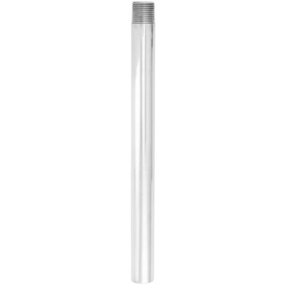
Flanged, threaded and weld-in protection tube
Description
Each thermowell / protection tube is an important component of any temperature measuring location. It is used to separate the process from the surrounding area, thus protecting the environment and operating personnel and keeping aggressive media, high pressures and flow rates away from the temperature sensor itself and thereby enabling the thermometer to be exchanged during operation.
Due to the almost unlimited range of use, there are a large number of variants, e.g. in terms of thermowell / protective tube designs or materials. The type of process connection and the basic method of manufacture are important design differentiation criteria.
Weld-in protection tube, design TW70-K
A basic differentiation can be made between threaded and weld-in thermowells / protection tubes, and those with flange connections.
The TW70 series of protection tubes are suitable for use with numerous electrical thermometers from WIKA.
These protection tubes are intended for low and medium process loads making them suitable for use in the chemical industry, process technology and equipment manufacturing.
Special features
- Variable length and dimensions
- Large variety of materials
| Model | TW70 |
| Product family | TW |
| Subcategory | Protection tube / thermowell |
| Process connection | 1 NPTWeld-inFlange per ASME B16.5Flange per EN 1092-1Flange per DIN 2527½ NPT¾ NPT3/4 NPTThreaded connectionFlange (a = 3 mm [⅛"])1 ¼ NPT1 ½ NPT¼ NPTWeld-in DN 14"Weld-in DN 12"Weld-in DN 34"Weld-in DN 1"Threaded connection E: 1/2 NPT1 1/4 NPT1 1/2 NPTConnection to thermometer N: 1/4 NPT1/2 NPT |
| Thermowell material | Stainless steel 304, Stainless steel 316, Stainless steel 310, A106, Alloy 600, Alloy X |
| Certifications | 2.2 test report per EN 102043.1 inspection certificate per EN 10204 |
| Thermowell | Yes |
| Thermowell form | fabricated |
| Datasheet languages | EN |
| Wake frequency calculation (on request) | Calculation of individual protection tubes in accordance with Dittrich/Klotter minimises the risk of dynamic damage that can be caused by the vortex shedding of a Kármán vortex street (Vortex Induced Vibration; VIV). In addition, the static loads due to lateral flow and the process pressure are calculated depending on the temperature. The calculation can be carried out as aWIKA engineered service (subject to charges). |
|---|---|
| → For further information, see technical information IN 00.15 'Wake frequency calculation'. |
| Certificates | ■ 2.2 test report per EN 10204 (e.g. state-of-the-art manufacturing, material proof, indication accuracy) ■ 3.1 inspection certificate per EN 10204 (e.g. material proof for wetted metal parts, indication accuracy, calibration certificate) |
|---|
Couldn't find the answer in the documentation? An engineer will reply within a business day.
Ask an engineer →