
Resistance thermometer
Description
The model TR55 resistance thermometer is ideally suited for the measurement of surface temperature at bearing shells on pumps, gears or motors under dry ambient conditions at the measuring tip. The spring-loaded, flat measuring tip ensures a constant contact pressure of the thermometer on the outer surface of the bearing shell. The optimum insertion depth can be set by means of a compression fitting.
Analogue or digital transmitters built into the connection head are capable of providing various output signals, for example 4 ... 20 mA and HART ® protocol.
for further approvals see page 2
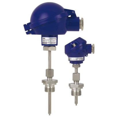
Fig. left: Model TR55 with connection head BSZ Fig. right: Model TR55 with connection head JS
Special features
- Sensor ranges from -50 ... +500 °C [-58 ... +932 °F]
- Compact design
- Spring-loaded tip
- Explosion-protected versions
Build a TR55 for your task
The article number is assembled automatically. If unsure — ask an engineer; we'll match the line's parameters.
- RTD assembly descriptionStandard design with connection head
- Unit of measureMetric (mm)
- Electrical approvalWithout
- Connection headJS (Aluminum)
- Cable entryM16 x 1.5
- Cable glandWithout
- Head instrument connectionM10 x 1.0
- Terminal block/TransmitterCeramic terminal block
- Output signalPt100
- Process connectionCompression fitting G 1/4 B, stainless steel ferrule
- Fitting materialStainless steel
- Support tube diameter / Tip diameter6 mm / 3 mm, spring travel approx. 3 - 4 mm
- Support tube materialStainless steel
- Sheath materialStainless steel 1.4571
- Measuring elementPt100, class B (IEC 60751)
- Wiring configurationSingle 2-wire
- Temperature range—
- Probe length [FL]—
- N-Dimension40
- A-Dimension—
- CertificatesWithout
Finish your configuration
Select every option to submit the request.
| Model | TR55 |
| Product family | TR |
| Subcategory | Spring-loaded surface thermometer |
| Temperature ranges | −50…+500 °C · −50…+250 °C · −30…+300 °C · +0…+150 °C |
| Process connection | G ¼ BG ⅜ BG ½ B¼ NPT½ NPTG 1/4 BG 3/8 BG 1/2 B1/4 NPT1/2 NPT |
| Process temperature | −40…+600 °C |
| Output signal | HART · 4-20mA · 0-10V |
| Electrical connection | Connection head BSZ or JS |
| Probe material | Stainless steel |
| Thermowell material | Stainless steel |
| Ambient temperature | −40…+80 °C |
| IP rating | IP65 |
| Certifications | GOSTKazInMetrMTSCHSBelGIMUkrSEPROUzstandardRoHSEACEMCINMETRONEPSIKCs-KOSHAPESODNOP-MakNIICE |
| Explosion protection | [Ex ia IIC T1 ... T6 Ga][Ex ia IIIC T125 ... T65 °C Da][Ex ib IIC T3 ... T6 Gb][II 1G Ex ia IIC T1 ... T6 Ga][II 2G Ex ia IIC T1 ... T6 Gb][II 1D Ex ia IIIC T125 ... T65 °C Da][II 2D Ex ia IIIC T125 ... T65 °C Db][II 3G Ex nA IIC T1 ... T6 Gc X][II 3D Ex tc IIIC T440 ... T80 °C Dc X][Ex ia IIC T1 ... T6 Gb][Ex ia IIIC T125 ... T65 °C Db][0 Ex ia IIC T3/T4/T5/T6][1 Ex ib IIC T3/T4/T5/T6][DIP A20 Ta 65 °C/Ta 95 °C/Ta 125 °C][DIP A21 Ta 65 °C/Ta 95 °C/Ta 125 °C][Ex nA IIC T6 ... T1][DIP A22 Ta 80 ... 440 °C][Ex ia IIC T3 ... T6 Ga][Ex ib IIIC T125 ... T65 °C Db][Ex ia IIC T3 ~ T6][Ex ib IIC T3 ~ T6][Ex nA IIC T1 ~ T6 Gc][Ex ia IIC T4 ... T6][Ex ib IIC T4 ... T6][II 1G Ex ia IIC T3, T4, T5, T6 Ga][II 2G Ex ia IIC T3, T4, T5, T6 Gb][II 1D Ex ia IIIC T65, T95, T125 °C Da][II 2D Ex ib IIIC T125 ... T65 °C Db]ATEX: [II 1G Ex ia IIC T1 ...T6 Ga] [II 2G Ex ia IIC T1 ...T6 Gb] [II 1D Ex ia IIIC T125 ...T65 °C Da] [II 2D Ex ia IIIC T125 ...T65 °C Db] [II 3G Ex nA IIC T1 ...T6 Gc X] [II 3D Ex tc IIIC T440 ...T80 °C Dc X]IECEx: [Ex ia IIC T3 ...T6 Ga] [Ex ib IIC T3 ...T6 Gb] [Ex ia IIIC T125 ...T65 °C Da] [Ex ib IIIC T125 ...T65 °C Db]EAC: [0 Ex ia IIC T3/T4/T5/T6] [1 Ex ib IIC T3/T4/T5/T6] [DIP A20Ta 65 °C/Ta 95 °C/Ta 125 °C] [DIP A21Ta 65 °C/Ta 95 °C/Ta 125 °C] [DIP A22Ta 80 ... 440 °C]INMETRO: [Ex ia IIC T3 ...T6 Ga] [Ex ib IIC T3 ...T6 Gb] [Ex ia IIIC T125 ...T65 °C Da] [Ex ib IIIC T125 ...T65 °C Db]NEPSI: [Ex ia IIC T3 ~ T6] [Ex ib IIC T3 ~ T6]KCs - KOSHA: [Ex ia IIC T4 ...T6] [Ex ib IIC T4 ...T6]PESO: [Ex ia IIC T1 ...T6 Ga] [Ex ib IIC T3 ...T6 Gb]DNOP - MakNII: [II 1G Ex ia IIC T3, T4, T5, T6 Ga] [II 2G Ex ia IIC T3, T4, T5, T6 Gb] [II 1D Ex ia IIIC T65, T95, T125 °C Da] [II 2D Ex ib IIIC T125 ...T65 °C Db]Ex iA IIC T1...T6 GaEx iA IIC T1...T6 GbEx iA IIIC T125...T65℃ DaEx iA IIIC T125...T65℃ DbEx nA IIC T1...T6 Gc XEx tc IIIC T440...T80℃ Dc XEx iA IIC T3...T6 GaEx ib IIC T3...T6 GbDIP A20 Ta 65℃/Ta 95℃/Ta 125℃DIP A21 Ta 65℃/Ta 95℃/Ta 125℃Ex nA IIC T6...T1DIP A22 Ta 80...440℃Ex ia IICT4...T6Ex ib IICT4...T6II 1G Ex ia IICT3,T4,T5,T6 GaII 2G Ex ia IICT3,T4,T5,T6 GbII 1D Ex ia IICT65,T95,T125°CDaII 2D Ex ib IICT125...T65°CDb |
| Sensor type | Pt100, Pt1000 |
| Sensor class | B |
| Probe diameter | 3 mm |
| Thermowell | No |
| Datasheet languages | EN |
| Logo | Description | Country | |
|---|---|---|---|
| EU declaration of conformity ■ EMCdirective 1) | European Union | ||
| ■ ATEX directive (option) Hazardous areas - Ex i Zone 0 gas Zone 1 gas Zone 20 dust Zone 21 dust - Ex n 2) Zone 2 gas Zone 22 dust IECEx (option) (in conjunction with ATEX) Hazardous areas - Ex i Zone 0 gas [Ex ia IIC T1 ...T6 Ga] Zone 1 gas [Ex ia IIC T1 ...T6 Gb] | [II 1G Ex ia IIC T1 ...T6 Ga] [II 2G Ex ia IIC T1 ...T6 Gb] [II 1D Ex ia IIIC T125 ...T65 °C Da] [II 2D Ex ia IIIC T125 ...T65 °C Db] [II 3G Ex nA IIC T1 ...T6 Gc X] [II 3D Ex tc IIIC T440 ...T80 °C Dc X] | International | |
| EAC (option) | Eurasian | ||
| Hazardous areas - Ex i Zone 0 gas [0 Ex ia IIC T3/T4/T5/T6] Zone 1 gas [1 Ex ib IIC T3/T4/T5/T6] Zone 20 dust [DIP A20Ta 65 °C/Ta 95 °C/Ta 125 °C] Zone 21 dust [DIP A21Ta 65 °C/Ta 95 °C/Ta 125 °C] - Ex n Zone 2 gas [Ex nA IIC T6 ...T1] Zone 22 dust | [DIP A22Ta 80 ... 440 °C] | Economic Community | |
| INMETRO (option) Hazardous areas - Ex i Zone 0 gas Zone 1 gas Zone 20 dust Zone 21 dust | [Ex ia IIC T3 ...T6 Ga] [Ex ib IIC T3 ...T6 Gb] [Ex ia IIIC T125 ...T65 °C Da] [Ex ib IIIC T125 ...T65 °C Db] | Brazil | |
| NEPSI (option) Hazardous areas - Ex i Zone 0 gas Zone 1 gas | [Ex ia IIC T3 ~ T6] [Ex ib IIC T3 ~ T6] | China |
| Logo | Description | Country |
|---|---|---|
| KCs - KOSHA (option) Hazardous areas - Ex i Zone 0 gas [Ex ia IIC T4 ...T6] | South Korea | |
| - | Zone 1 gas [Ex ib IIC T4 ...T6] PESO (option) Hazardous areas - Ex i Zone 0 gas [Ex ia IIC T1 ...T6 Ga] Zone 1 gas [Ex ib IIC T3 ...T6 Gb] | India |
| DNOP - MakNII (option) Hazardous areas - Ex i Zone 0 gas [II 1G Ex ia IIC T3, T4, T5, T6 Ga] Zone 1 Gas [II 2G Ex ia IIC T3, T4, T5, T6 Gb] Zone 20 dust [II 1D Ex ia IIIC T65, T95, T125 °C Da] Zone 21 dust [II 2D Ex ib IIIC T125 ...T65 °C Db] | Ukraine | |
| GOST (option) Metrology, measurement technology | Russia | |
| KazInMetr (option) Metrology, measurement technology | Kazakhstan | |
| - | MTSCHS (option) Permission for commissioning | Kazakhstan |
| BelGIM (option) Metrology, measurement technology | Belarus | |
| UkrSEPRO (option) Metrology, measurement technology | Ukraine | |
| Uzstandard (option) Metrology, measurement technology | Uzbekistan |
| Single elements | 1 x 2-wire 1 x 3-wire 1 x 4-wire |
|---|---|
| Dual elements | 2 x 2-wire 2 x 3-wire 2 x 4-wire 2) |
| Class | Sensor construction Thin-film |
|---|---|
| Class B | -50 ...+500 °C -50 ...+250 °C |
| Class A 3) | -30 ...+300 °C |
| Class AA 3) | 0 ... 150 °C |
View all (15)
| Model | Material | Cable entry thread size | Ingress protection (max.) 1) | Cap | Surface | Connection to neck tube |
|---|---|---|---|---|---|---|
| JS | Aluminium | M16 x 1.5 2) | IP65 | Cover with 2 screws | Blue, lacquered 4) | M24 x 1.5,½NPT |
| BS | Aluminium | M20 x 1.5 2) | IP65 3) | Flat cover with 2 screws | Blue, lacquered 4) | M24 x 1.5,½NPT |
| BSZ | Aluminium | M20 x 1.5 2) | IP65 3) | Spherical hinged cover with cylinder head screw | Blue, lacquered 4) | M24 x 1.5,½NPT |
| BSZ-H | Aluminium | M20 x 1.5 2) | IP65 3) | Raised hinged cover with cylinder head screw | Blue, lacquered 4) | M24 x 1.5,½NPT |
| BSS | Aluminium | M20 x 1.5 2) | IP65 | Spherical hinged cover with clamping lever | Blue, lacquered 4) | M24 x 1.5,½NPT |
| BSS-H | Aluminium | M20 x 1.5 2) | IP65 | Raised hinged cover with clamping lever | Blue, lacquered 4) | M24 x 1.5,½NPT |
| BVS | Stainless steel | M20 x 1.5 2) | IP65 | Precision-cast screw-on lid | Blank, electropolished | M24 x 1.5 |
| BSZ-K | Plastic | M20 x 1.5 2) | IP65 | Spherical hinged cover with cylinder head screw | Black | M24 x 1.5 |
| BSZ-HK | Plastic | M20 x 1.5 2) | IP65 | Raised hinged cover with cylinder head screw | Black | M24 x 1.5 |
| Model | Explosion protection | ||||
|---|---|---|---|---|---|
| Without | Ex i (gas) Zone 0, 1, 2 | Ex i (dust) Zone 20, 21, 22 | Ex nA (gas) Zone 2 | Ex tc (dust) Zone 22 | |
| JS | x | x | x | - | - |
| BS | x | x | - | - | - |
| BSZ | x | x | x | x | x |
| BSZ-H | x | x | x | x | x |
| BSS | x | x | - | - | - |
| BSS-H | x | x | - | - | - |
| BVS | x | x | - | - | - |
| BSZ-K | x | x | - | - | - |
| BSZ-HK | x | x | - | - | - |
| Cable entry | Cable entry thread size |
|---|---|
| Standard cable entry 1) | M20 x 1.5 |
| Plastic cable gland (cable Ø 6 ... 10 mm) 1) | M20 x 1.5 |
| Nickel-plated brass cable gland (cable Ø 6 ... 12 mm) | M20 x 1.5 |
| Stainless steel cable gland (cable Ø 7 ... 12 mm) | M20 x 1.5 |
| Cable entry | Colour | Ingress protection (max.) 2) | Min./max. ambient temperature | Explosion protection | ||||
|---|---|---|---|---|---|---|---|---|
| without | Ex i (gas) Zone 0, 1, 2 | Ex i (dust) Zone 20, 21, 22 | Ex nA (gas) Zone 2 | Ex tc (dust) Zone 22 | ||||
| Standard cable entry 1) | Blank | IP65 | -40 ...+80 °C | x | x | - | - | - |
| Plastic cable gland 1) | Black or grey | IP66 3) | -40 ...+80 °C | x | - | - | - | - |
| Plastic cable gland, Ex e 1) | Light blue | IP66 3) | -20 ...+80 °C (standard) -40 ...+70 °C (option) | x | x | x | - | - |
| Plastic cable gland, Ex e 1) | Black | IP66 3) | -20 ...+80 °C (standard) -40 ...+70 °C (option) | x | - | - | x | x |
| Brass cable gland, nickel-plated | Blank | IP66 3) | -60 4) / -40 ...+80 °C | x | - | - | - | - |
| Brass cable gland, nickel-plated, Ex e | Blank | IP66 3) | -60 4) / -40 ...+80 °C | x | x | x | x | x |
| Stainless steel cable gland | Blank | IP66 3) | -60 4) / -40 ...+80 °C | x | x | x | - | - |
| Stainless steel cable gland, Ex e | Blank | IP66 3) | -60 4) / -40 ...+80 °C | x | x | x | x | x |
| First index number | Degree of protection / short description | Test parameter |
|---|---|---|
| 5 | Dust-protected | per IEC/EN 60529 |
| 6 | Dust-tight | per IEC/EN 60529 |
| Second index number | Degree of protection / short description | Test parameter |
|---|---|---|
| 4 | Protected against splash water | per IEC/EN 60529 |
| 5 | Protected against water jets | per IEC/EN 60529 |
| 6 | Protected against strong water jets | per IEC/EN 60529 |
| 7 1) | Protected against the effects of temporary immersion in water | per IEC/EN 60529 |
| 8 1) | Protected against the effects of continuous immersion in water | by agreement |
| Transmitter (selectable versions) | Model T15 | Model T32 | Model T91.10 | Model T91.20 |
|---|---|---|---|---|
| Data sheet | TE 15.01 | TE 32.04 | TE 91.01 | TE 91.01 |
| Output | ||||
| ■ 4 ...20mA | x | x | - | x |
| ■ 0 ...10V | - | - | x | - |
| ■ HART ® protocol | - | x | - | - |
| Connection method | ||||
| ■ 1 x 2-wire | x | x | x 1) | x |
| ■ 1 x 3-wire | x | x | x | - |
| ■ 1 x 4-wire | x | x | - | - |
| Measuring current | < 0.2mA | < 0.3mA | 0.8 ...1mA | 0.8 ...1mA |
| Explosion protection | Optional | Optional | - | - |
| Connection head | T15 | T32 | T91.10 | T91.20 |
|---|---|---|---|---|
| JS | - | - | - | ○ |
| BS | ○ | - | ○ | - |
| BSZ, BSZ-K | ○ | ○ | ○ | - |
| BSZ-H, BSZ-HK | ● | ● | ● | - |
| BSS | ○ | ○ | ○ | - |
| BSS-H | ● | ● | ● | - |
| BVS | ○ | ○ | ○ | - |
| Support tube | Process connection | Maximum possible insertion length A 1) in mmwith probe length FL | |||||||
|---|---|---|---|---|---|---|---|---|---|
| Ø inmm | 65 | 75 | 80 | 85 | 105 | 125 | 230 | 250 | |
| 6 or 8 | G¼B | 35 | 45 | 50 | 55 | 75 | 95 | 200 | 220 |
| G⅜B | 35 | 45 | 50 | 55 | 75 | 95 | 200 | 220 | |
| G½B | 35 | 45 | 50 | 55 | 75 | 95 | 200 | 220 | |
| ¼NPT | 20 | 30 | 35 | 40 | 60 | 80 | 185 | 205 | |
| ½NPT | 20 | 30 | 35 | 40 | 60 | 80 | 185 | 205 |
| Description | The measuring insert is spring-mounted with two screws into the connection head and can simply be removed for calibration purposes.The thermowell itself can thus remain in the process.The terminal block for electrical connection is connected to the probe tube of the measuring insert. |
|---|---|
| Diameter (for thermowellØ=6mm) | 3mm |
| Diameter (for thermowellØ=8mm) | 6mm |
| Operating temperatures (dependent upon the sensor design type and the accuracy class) | Min: -40 °C Max: +600 °C |
| Built-in measuring insert model | TR10-A |
| Certification type | Measurement accuracy | Material certificate |
|---|---|---|
| 2.2 test report | x | x |
| 3.1 inspection certificate | x | x |
Couldn't find the answer in the documentation? An engineer will reply within a business day.
Ask an engineer →18 standard articles of family TR
If you know the code — pick directly. If not — use the configurator in mode “01”.