
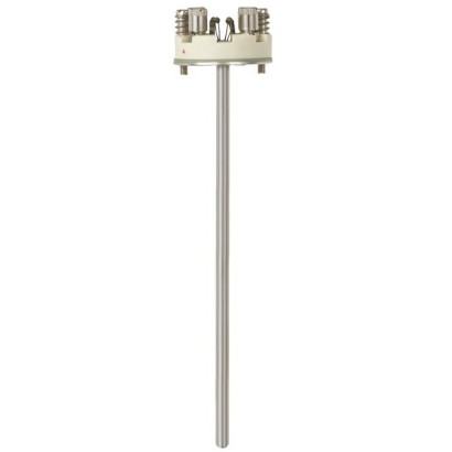
Measuring insert
Description
The measuring inserts per DIN 43735 for resistance thermometers described here are designed for installation in a protective fitting. Operation without a thermowell is only advisable in special cases. The measuring insert is manufactured from bendable, mineral-insulated sheathed cable. The sensor is located in the tip of the measuring insert. The measuring inserts are delivered with loading springs to ensure a good contact to the thermowell floor.
Apart from the DIN versions, customer specific versions are available, for example:
- ■ other measuring insert lengths (also intermediate lengths) - ■ with mounted sleeve to suit inner diameter of the thermowell - ■ without terminal block - ■ with transmitter
for further approvals see page 2
Fig. left: Standard version Fig. right: Model TR10-A with recessed soldering lugs (option)
Type and number of sensors, accuracy and method of connection can each be selected to suit the respective application.
A large number of different explosion-protected approvals are available for the TR10-A.
The range of applications is completed by designs without terminal block for direct transmitter installation. Optionally, analogue or digital transmitters from the WIKA range can be installed.
Special features
- Sensor ranges from -196 ... +600 °C [-320 ... +1,112 °F]
- Made of mineral-insulated sheathed cable
- Functional safety (SIL) with model T32 temperature transmitter
- Spring-loaded design
- Explosion-protected versions are available for many approval types (see data sheet page 2)
Build a TR10-A for your task
The article number is assembled automatically. If unsure — ask an engineer; we'll match the line's parameters.
- Electrical approvalWithout
- Ignition protection typeWithout
- ZoneWithout
- Sensor1xPt100, 2-wire
- Accuracy class of the sensorClass B, IEC 60751
- Temperature range of selected class—
- Transmitter—
- Transmitter details—
- Measuring insert length [l5]—
- Diameter measuring insert—
- Sheath material measuring insertStainless steel 1.4571
- Mechanical requirementsWithout
- CertificatesWithout
Finish your configuration
Select every option to submit the request.
| Model | TR10-A |
| Product family | TR10 |
| Subcategory | Measuring insert |
| Temperature ranges | −196…+600 °C |
| Safety integrity level (SIL) | SIL 2 |
| Process temperature | −196…+600 °C |
| Output signal | HART · 4-20mA |
| Electrical connection | 2-wire, 3-wire, 4-wire |
| Probe material | Stainless steel 316, Stainless steel 1.4571 |
| Ambient temperature | −60…+80 °C |
| IP rating | IP00 |
| Certifications | RoHSEACCCCGOSTKazInMetrMTSCHSBelGIMUkrSEPROUzstandardINMETROKCs-KOSHAPESOEMCCEATEXIECExExUkraineNAMUR |
| Explosion protection | II 1G Ex ia IIC T1 ... T6 GaII 2G Ex ia IIC T1 ... T6 GbII 2G Ex eb IIC T1 ... T6 GbII 3G Ex ec IIC T1 ... T6 Gc XII 3G Ex nA IIC T1 ... T6 Gc XEx ia IIC T1 ... T6 GaEx ia IIC T1 ... T6 GbEx eb IIC T1 ... T6 GbEx ec IIC T1 ... T6 GcEx nA IIC T1 ... T6 Gc0Ex ia IIC T6 ... T1 Ga X2Ex nA IIC T6 ... T1 Gc XEx ia IIC T3 ... T6 GaEx ia IIC T1 ~ T6 GaEx e IIC T1 ~ T6 GbEx nA IIC T1 ~ T6 GcEx ia IIC T4 ... T6Ex ib IIC T4 ... T6ATEX: Ex ia IIC T1...T6 Ga, Ex eb IIC T1...T6 Gb, Ex ec IIC T1...T6 Gc, Ex nA IIC T1...T6 GcIECEx: Ex ia IIC T1...T6 Ga/Gb, Ex eb IIC T1...T6 Gb, Ex ec IIC T1...T6 Gc, Ex nA IIC T1...T6 GcEx Ukraine: II 1G Ex ia IIC T1...T6 GaINMETRO: Ex ia IIC T3...T6 GaKCs - KOSHA: Ex ia IIC T4...T6, Ex ib IIC T4...T6PESO: Ex ia IIC T1...T6 Ga/Gb |
| Sensor type | Pt100 |
| Sensor class | A, B, AA |
| Probe diameter | 6 mm |
| Thermowell | No |
| Datasheet languages | EN, DE |
| Logo | Description | Country | ||
|---|---|---|---|---|
| EU declaration of conformity ■ EMCdirective 1) | European Union | |||
| ■ RoHS directive ■ ATEX directive (option) | International | |||
| IECEx (option) - in conjunction with ATEX Hazardous areas - Ex i Zone 0 gas Ex ia IIC T1 ...T6 Ga Zone 1 gas Ex ia IIC T1 ...T6 Gb - Ex e 3) Zone 1 gas Ex eb IIC T1 ...T6 Gb 4) Zone 2 gas Ex ec IIC T1 ...T6 Gc - Ex n 3) Zone 2 gas Ex nA IIC T1 ...T6 Gc EAC (option) Hazardous areas | ||||
| - Ex i Zone 0 gas 0Ex ia IIC T6 ...T1 Ga X | Eurasian Economic Community | |||
| Ex Ukraine (option) Hazardous areas | ||||
| - Ex i | Zone 0 gas | II 1G Ex ia IIC T1...T6 Ga | Ukraine | |
| INMETRO (option) Hazardous areas Ex i Zone 0 gas Ex ia IIC T3 ...T6 Ga (option) areas | ||||
| CCC Hazardous | China | |||
| - Ex i - Ex e 3) - Ex n 3) | Zone 0 gas Zone 2 gas Zone 2 gas | Ex ia IIC T1 ~ T6 Ga Ex e IIC T1 ~ T6 Gb 4) Ex nA IIC T1 ~ T6 Gc |
| Logo | Description | Country |
|---|---|---|
| KCs - KOSHA (option) Hazardous areas - Ex i Zone 0 gas Ex ia IIC T4 ...T6 Zone 1 gas Ex ib IIC T4 ...T6 | South Korea | |
| - | PESO (option) Hazardous areas - Ex i Zone 0 gas Ex ia IIC T1 ...T6 Ga Zone 1 gas Ex ia IIC T1 ...T6 Gb | India |
| GOST (option) Metrology, measurement technology | Russia | |
| KazInMetr (option) Metrology, measurement technology | Kazakhstan | |
| - | MTSCHS (option) Permission for commissioning | Kazakhstan |
| BelGIM (option) Metrology, measurement technology | Belarus | |
| UkrSEPRO (option) Metrology, measurement technology | Ukraine | |
| Uzstandard (option) Metrology, measurement technology | Uzbekistan |
| Single elements | 1 x 2-wire 1 x 3-wire 1 x 4-wire |
|---|---|
| Dual elements | 2 x 2-wire 2 x 3-wire 2 x 4-wire 2) |
| Class | Sensor construction | |
|---|---|---|
| Wire-wound | Thin-film | |
| Class B | -196 ...+600 °C | -50 ...+500 °C |
| Class A 3) | -100 ...+450 °C | -30 ...+300 °C |
| Class AA 3) | -50 ...+250 °C | 0 ... 150 °C |
View all (12)
| Transmitter (selectable versions) | Model T15 | Model T32 |
|---|---|---|
| Data sheet | TE 15.01 | TE 32.04 |
| Output | ||
| 4 ...20mA | x | x |
| HART ® protocol | - | x |
| Connection method | ||
| 1 x 2-wire, 3-wire or 4-wire | x | x |
| Measurement current | < 0.2mA | < 0.3mA |
| Measuring insert length l 5 inmm | Tolerance inmm |
|---|---|
| 75 ... 825 | +2 0 |
| > 825 | +3 0 |
| Measuring insert diameter Ø d inmm | Index per DIN 43735 | Tolerance inmm | |
|---|---|---|---|
| 3 1) | Standard | 30 | 3 ±0.05 |
| 6 | Standard | 60 | 6 0 -0.1 |
| 8 (6 mmwith sleeve) | Standard | - | 8 0 -0.1 |
| 8 | Standard | 80 | 8 0 -0.1 |
| 1/8 in [3.17 mm] 1) 1/4 in [6.35 mm] 3/8 in [9.53 mm] | On request | - | - |
| Sheath material | Stainless steel 316 |
|---|---|
| Stainless steel 1.4571 |
| Certification type | Measurement accuracy | Material certificate |
|---|---|---|
| 2.2 test report | x | x |
| 3.1 inspection certificate | x | x |
| DKD/DAkkS calibration certificate | x | - |
| Standard | 6 g peak-to-peak, wire-wound or thin film measuring resistor |
|---|---|
| Option | Vibration resistant sensor tip, max. 20 g peak-to-peak (thin-film measuring resistor) |
| Highly vibration resistant sensor tip, max. 50 g peak-to-peak (thin-film measuring resistor) |
| Connection method | ||
|---|---|---|
| Single element | Pt100, 1 x 4-wire | |
| Validity limits of the class accuracy per EN 60751 | ||
| Pt100 | Class A | -30 ...+300 °C [-22 ...+572 °F] |
| Class B | -50 ...+500 °C [-58 ...+932 °F] |
| Diameter∅d in mm[in] | Code number per DIN 43735 | Tolerance inmm | Sheath material |
|---|---|---|---|
| 6 [0.24] | 60 | 6 0 -0.1 | 1.4571 |
Couldn't find the answer in the documentation? An engineer will reply within a business day.
Ask an engineer →115 standard articles of family TR10
If you know the code — pick directly. If not — use the configurator in mode “01”.