
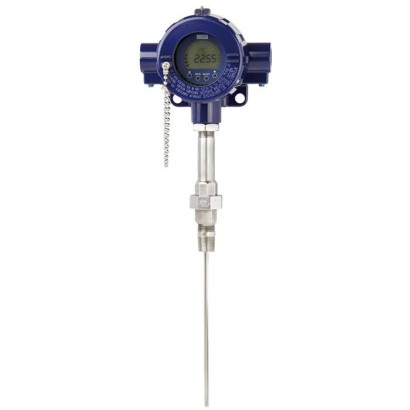
Process thermocouple
Description
Thermocouples in this series can be combined with a large number of thermowell designs. The replaceable, centrically spring-loaded measuring insert and its extended spring travel enable combination with the widest range of connection head designs.
A wide variety of possible combinations of sensor, connection head, insertion length, neck length, connection to thermowell etc. are available for the thermometers; suitable for any thermowell dimension and any application.
Operation without thermowell is only recommended in certain applications.
for further approvals see page 2
Fig. left: Process thermocouple model TC12-B Fig. right: Basic module model TC12-M
Special features
- Application ranges from -40 ... +1,200 °C [-40 ... +2,192 °F]
- For many variants of temperature transmitters including field transmitter
- For mounting in all standard thermowell designs
- Spring-loaded measuring insert (replaceable)
- Explosion-protected versions
Build a TC12-M for your task
The article number is assembled automatically. If unsure — ask an engineer; we'll match the line's parameters.
- Electrical approvalWithout
- Ignition protection typeWithout
- ZoneWithout
- Thermocouple typeType K
- Number of thermocouplesSingle thermocouple
- Accuracy class of the sensorClass 2, IEC 60584
- Validity limits of class accuracy-40…+1200 °C
- Hot junctionUngrounded
- Unit of measureMetric (mm)
- Neck designNipple-Union-Nipple
- Connection to housing / headMale thread 1/2 NPT
- Connection to thermowellMale thread 1/2 NPT
- Neck length [N/MH]150
- Insertion length [A/L1/U2]—
- Insert diameter—
- Sheath material measuring insert—
- CertificatesWithout
Finish your configuration
Select every option to submit the request.
| Model | TC12-B |
| Product family | TC12 |
| Subcategory | Process thermocouple |
| Temperature ranges | −40…+1200 °C · −40…+1000 °C · +0…+1260 °C · −40…+750 °C · +0…+760 °C · −40…+900 °C · −40…+800 °C · +0…+870 °C · −40…+350 °C · +0…+370 °C |
| Safety integrity level (SIL) | SIL 2 |
| Process connection | 1/2 NPTG 1/2 BG 3/4 B3/4 NPTM14 x 1.5M18 x 1.5M20 x 1.5M27 x 2M14 xM18 xM20 x |
| Process temperature | −40…+1200 °C |
| Output signal | 4-20mA · HART · FOUNDATION Fieldbus · PROFIBUS PA · FOUNDATION™ Fieldbus |
| Electrical connection | ½NPT, ¾NPT, M20 x 1.5 |
| Probe material | Ni alloy: alloy 600, alloy 600, Ni alloy |
| Ambient temperature | −60…+80 °C |
| IP rating | IP66 |
| Certifications | RoHSEACGOSTKazInMetrMTSCHSBelGIMUzstandardCEREACHINMETRONEPSIKCs - KOSHAPESODNOP - MakNII |
| Explosion protection | [Ex ia IIC T1 ... T6 Ga][Ex ib IIC T3 ... T6 Ga/Gb][Ex ib IIC T3 ... T6 Gb][II 1G Ex ia IIC T1 ... T6 Ga][II 1/2G Ex ia IIC T1 ... T6 Ga/Gb][II 2G Ex ia IIC T1 ... T6 Gb][II 1/2D Ex db IIC T1 ... T6][II 2G Ex db IIC T1 ... T6][Ex ia IIC T1 ... T6 Ga/Gb][Ex ia IIC T1 ... T6 Gb][Ex db IIC T1 ... T6 Ga/Gb][Ex dbIIC T1 ... T6 Gb][0 Ex ia IIC T3/T4/T5/T6][1 Ex ib IIC T3/T4/T5/T6][DIP A20 Ta 65 °C/Ta 95 °C/Ta 125 °C][DIP A21 Ta 65 °C/Ta 95 °C/Ta 125 °C][1 Ex d IIC T6 ... T1][Ex ia IIC T3 ... T6 Ga][Ex ia IIIC T125 ... T65 °C Da][Ex ib IIIC T125 ... T65 °C Da/Db][Ex ib IIIC T125 ... T65 °C Db][Ex d IIC T* Ga/Gb][Ex d IIC T* Gb][Ex ia IIC T1 ~ T6 Ga][Ex ia IIC T1 ~ T6 Ga/Gb][Ex ia IIC T1 ~ T6 Gb][Ex ia IIC T4 ... T6][Ex ib IIC T4 ... T6][Ex d IIC T1 ... T6 Gb][II 1G Ex ia IIC T3 ...T6 Ga][II 1/2G Ex ia IIC T3 ...T6 Ga/Gb][II 2G Ex ia IIC T3 ...T6 Gb][II 1D Ex ia IIIC T125 ... T65 °C Da][II 1/2D Ex ia IIIC T125 ... T65 °C Da/Db][II 2D Ex ia IIIC T125 ... T65 °C Db]ATEX Ex i Zone 0, Ex d Zone 1IECEx Ex i Zone 0, Ex d Zone 1EACINMETRO Ex ia IIC T3...T6 GaNEPSIKCs - KOSHA Ex ia IIC T4...T6PESODNOP - MakNII II 1G Ex ia IIC T3...T6 GaGOSTKazInMetrMTSCHSBelGIMUzstandardII1G Exia IICT1...T6 GaII1/2G Exia IICT1...T6 Ga/GbII2G Exia IICT1...T6 GbII1/2D Exdb IICT1...T6 Ga/GbII2G Exdb IICT1...T6 GbEx ia IIC T1 ~ T6 GaEx ia IIC T1 ~ T6 Ga/GbEx ia IIC T1 ~ T6 GbEx db IICT1...T6 Ga/GbEx db IICT1...T6 Gb1ExiaIICT3/T4/T5/T61ExibIICT3/T4/T5/T6DIPA20Ta65℃/Ta95℃/Ta125℃DIPA21Ta65℃/Ta95℃/Ta125℃1ExdIICT6...T1ExiaIICT3...T6GaExibIICT3...T6Ga/GbExibIICT3...T6GbExiaIICT125...T65℃DaExibIICT125...T65℃Da/DbExibIICT125...T65℃DbExdIICT _Ga/GbExdIICT_ GbEx ia IIC T4 ... T6Ex ib IIC T4 ... T6Ex ia IIC T1 ... T6 GaEx d IIC T1 ... T6 GbII 1G Ex ia IIC T3 ... T6 GaII 1/2G Ex ia IIC T3 ... T6 Ga/GbII 2G Ex ia IIC T3 ... T6 GbII 1D Ex ia IIC T125 ... T65 °C DaII 1/2D Ex ia IIC T125 ... T65 °C Da/DbII 2D Ex ia IIC T125 ... T65 °C Db |
| Sensor type | Type K/J/E/N/T |
| Sensor class | Class 1, Class 2 |
| Probe diameter | 3 mm |
| Thermowell | No |
| Datasheet languages | EN |
| Logo | Description | Country | |
|---|---|---|---|
| EU declaration of conformity EMCdirective 1) EN 61326 emission (group 1, class B) and interference immunity (industrial application) | European Union | ||
| ■ ATEX directive Hazardous areas - Ex i Zone Zone Zone - Ex d Zone Zone (option) conjunction with ATEX) Hazardous areas | |||
| IECEx (in - Ex i Zone 0 Zone 1 Zone 1 - Ex d Zone 1 Zone 1 | International | ||
| EAC (option) Hazardous areas | Eurasian Economic Community | ||
| INMETRO (option) Hazardous areas Ex i Zone 0 gas [Ex ia IIC T3 ...T6 Ga] | Brazil |
| Logo | Description | Country |
|---|---|---|
| NEPSI (option) Hazardous areas | China | |
| KCs - KOSHA (option) Hazardous areas - Ex i Zone 0 gas [Ex ia IIC T4 ...T6] | South Korea | |
| - | PESO (option) Hazardous areas | India |
| DNOP - MakNII (option) Hazardous areas Ex i Zone 0 gas 2) [II 1G Ex ia IIC T3 ...T6 Ga] | ||
| Ukraine | ||
| GOST (option) Metrology, measurement technology | Russia | |
| KazInMetr (option) Metrology, measurement technology | Kazakhstan | |
| - | MTSCHS (option) | Kazakhstan |
| BelGIM (option) Metrology, measurement technology | Belarus | |
| Uzstandard (option) Metrology, measurement technology | Uzbekistan |
| Temperature range | Measuring range see page 5 |
|---|---|
| Thermocouple per IEC 60584-1 | Types K, J, E, N,T |
| Measuring point | ■ Ungrounded welded (ungrounded) ■ Welded at the bottom (grounded) |
| Tolerance value of the measuring element ■ per IEC 60584-1 | Class 1 Class 2 |
| ■ per ASTM E230 | Standard Special |
| Transmitter (selectable versions) | Model T16 | Model T32 | Model T53 | Models TIF50, TIF52 |
|---|---|---|---|---|
| Data sheet | TE 16.01 | TE 32.04 | TE 53.01 | TE 62.01 |
| Output | ||||
| ■ 4 ...20mA | x | x | x | |
| ■ HART ® protocol | x | x | ||
| ■ FOUNDATION™ Fieldbus and PROFIBUS ® PA | x | |||
| Galvanic isolation | yes | yes | yes | yes |
View all (20)
| Material | Ni alloy: alloy 600, others on request |
|---|---|
| Diameter | Standard: 3 mm, 4.5mm,6mm,8mm Option (on request): 1/8 inch (3.17 mm), 1/4 inch (6.35 mm), 3/8 inch (9.53 mm) |
| Spring travel | approx.20mm |
| Response time (in water, per EN 60751) | t 50 < 5 s t 90 < 10 s (measuring insert diameter 6 mm:The thermowell required for operation increases the response time dependent upon the actual parameters for the thermowell and the process.) |
| Material | Stainless steel 1.4571, 316, 316L |
|---|---|
| Connection thread to the thermowell | ■ G1/2 B ■ G3/4 B ■ 1/2 NPT ■ M14 x ■ M18 x ■ M20 x |
| Connection thread to the head | ■ M20 x 1.5 with counter nut ■ 1/2 NPT |
| Neck length | ■ min. 150 mm, standard neck length ■ 200mm ■ 250mm other neck lengths on request |
| Ambient and storage temperature | -60 1) / -40 ...+80 °C |
|---|---|
| Ingress protection | IP66 per IEC/EN 60529 The specified ingress protection only applies for TC12-B with corresponding thermowell, connection head, cable gland and appropriate cable dimensions. |
| Vibration resistance | 50 g, peak-to-peak |
| Model | Operating temperatures per | ||
|---|---|---|---|
| IEC 60584-1 | ASTM E230 | ||
| Class 2 | Class 1 | Standard Special | |
| K | -40 ... +1,200 °C | -40 ... +1,000 °C | 0 ... 1,260 °C |
| J | -40 ...+750 °C | -40 ...+750 °C | 0 ... 760 °C |
| E | -40 ...+900 °C | -40 ...+800 °C | 0 ... 870 °C |
| N | -40 ... +1,200 °C | -40 ... +1,000 °C | 0 ... 1,260 °C |
| T | -40 ...+350 °C | 0 ... 370 °C |
| Thread to connection head | Measuring insert length l 5 |
|---|---|
| 1/2 NPT | NL+12mm |
| M20 x 1.5 | NL+18mm |
| Model | Material | Cable outlet | Ingress protection | Explosion protection | Cap | Surface |
|---|---|---|---|---|---|---|
| 1/4000 F | Aluminium | ½NPT, ¾NPT, M20 x 1.5 | IP66 1) | Without, Ex i, Ex d | Screw-on lid | Blue, lacquered 2) |
| 1/4000 S | Stainless steel | ½NPT, ¾NPT, M20 x 1.5 | IP66 1) | Without, Ex i, Ex d | Screw-on lid | Blank |
| 5/6000 | Aluminium | 2 x ½NPT, 2 x ¾NPT, 2 x M20 x 1.5 | IP66 1) | Without, Ex i, Ex d | Screw-on lid | Blue, lacquered 2) |
| 7/8000W | Aluminium | ½NPT, ¾NPT, M20 x 1.5 | IP66 1) | Without, Ex i, Ex d | Screw-on lid | Blue, lacquered 2) |
| 7/8000 S | Stainless steel | ½NPT, ¾NPT, M20 x 1.5 | IP66 1) | Without, Ex i, Ex d | Screw-on lid | Blank |
| Model | Description | Explosion protection | Data sheet |
|---|---|---|---|
| T16 | Digital transmitter, PC configurable | Optional | TE 16.01 |
| T32 | Digital transmitter, HART ® protocol | Optional | TE 32.04 |
| T53 | Digital transmitter FOUNDATION™ Fieldbus and PROFIBUS ® PA | Standard | TE 53.01 |
| TIF50 | Digital field temperature transmitter, HART ® protocol (slave) | Optional | TE 62.01 |
| TIF52 | Digital field temperature transmitter, HART ® protocol (master) | Optional | TE 62.01 |
| Sensor | IEC 60584-1 | ASTM E230 | ||
|---|---|---|---|---|
| type | Positive | Negative | Positive | Negative |
| K | Green | White | Yellow | Red |
| J | Black | White | White | Red |
| E | Violet | White | Violet | Red |
| N | Pink | White | Orange | Red |
| T | Brown | White | Blue | Red |
| Certification type | Measurement accuracy | Material certificate |
|---|---|---|
| 2.2 test report | x | x |
| 3.1 inspection certificate | x | x |
| DKD/DAkkS calibration certificate | x | - |
| Thermometer description | RTD | Data sheet | TC | Data sheet |
|---|---|---|---|---|
| For additional thermowell | TR10-B | TE 60.02 | TC10-B | TE 65.02 |
| Process version | TR12-B | TE 60.17 | TC12-B | TE 65.17 |
| Cable thermometers | TR40 | TE 60.40 | TC40 | TE 65.40 |
| Threaded thermometer | TR10-C | TE 60.03 | TC10-C | TE 65.03 |
| Flanged resistance thermometer | TR10-F | TE 60.06 | TC10-F | TE 65.06 |
| Operation without thermowell | TR10-H | TE 60.08 | TC10-H | TE 65.08 |
| Connection method | ||
|---|---|---|
| Single element | ■ Pt1000, 1 x 4-wire ■ Thermocouple type E | |
| Validity limits of the class accuracy per EN 60751 | ||
| Pt1000 (cryogenic design) | ±3 K 1) | -253 ... -200 °C [-423 ... -328 °F] |
| Class B | -200 ...+50 °C [-432 ...+122 °F] 2) | |
| Validity limits of the class accuracy in accordance with IEC 60584-1 | ||
| Type E (cryogenic design) | ±3 K 1) | -253 ... -200 °C [-423 ... -328 °F] |
| Class 3 | -200 ... -40 °C [-328 ... -40 °F] | |
| Class 1 | -40 ...+250 °C [-40 ...+482 °F] |
| Diameter ∅din mm[in] | Code number per DIN 43735 | Tolerance in mm | Sheath material | |
|---|---|---|---|---|
| Standard design | Recessed soldering lugs | |||
| 3 [0.12] | - | 3 0 -0.5 | Stainless steel 1.4571 | Stainless steel 1.4571 |
| 6 [0.24] | 60 | 6 0 -0.1 | ■ Stainless steel 1.4571 ■ Stainless steel 316L | Stainless steel 1.4571 |
| 6 [0.24 in] with sleeve | - | 6 0 -0.1 | Stainless steel 1.4571 | Stainless steel 1.4571 |
| 8 [0.31] | - | 8 0 -0.1 | Stainless steel 1.4571 | Stainless steel 1.4571 |
| Measuring insert diameter ∅din mm[in] | Code number per DIN 43735 | Tolerance inmm | Sheath material |
|---|---|---|---|
| 1.5 [0.06] | - | 1.5 ±1% | Stainless steel: 1.4571 |
| 3 [0.12] | 30 | 3 0 -0.5 | Ni alloy: Alloy 600 |
| 6 [0.24] | 60 | 6 0 -0.1 | |
| 6 [0.24] with sleeve | - | 8 0 -0.1 | Ni alloy: Alloy 600 |
| 8 [0.31] | 80 | 8 0 -0.1 | Ni alloy: Alloy 600 |
| Model | Data sheet | Representation |
|---|---|---|
| TW10 | TW95.10 | |
| TW15 | TW95.15 | |
| TW20 | TW95.20 | |
| TW25 | TW95.25 | |
| TW30 | TW95.30 | |
| TW45 | TW95.45 | |
| TW50 | TW95.50 | |
| TW55 | TW95.55 |
| Model | Description D |
|---|---|
| PIH-L | Connection head with flat screw-on lid |
| PIH-H | Connection head with high screw-on lid |
| PIH-W | Connection head with high screw-on lid and window |
| PIR-L | Connection head with flat screw-on lid, pipe or wall mounting |
| PIR-H | Connection head with high screw-on lid, pipe or wall mounting |
| PIR-W | Connection head with high screw-on lid and window, pipe or wall mounting E |
| Materials | ||
|---|---|---|
| Lower part of the case PIX-X Explosion CONNECTION HEAD | Aluminium die-casting EN AC-43500 AlSi10MnMg / AA 365.0; copper content ≤ 0,05% (low copper) drawing number 14654707.01 | |
| Screw-on lid scale 1:1 | Aluminium die-casting EN AC-43500 AlSi10MnMg / AA 365.0; copper content ≤ 0,05% (low copper) F reference DR 08 sheets 1 / 1 | |
| Window Check indicator size | Glass ALEXANDER WIEGAND SE & Co. KG comments | |
| Sealing language | ■ EPDM -60 ...+90 °C [-76 ... 194 °F] ■ MVQ-60 ...+110°C [-76 ... 230 °F], on request ■ FKM -20 ...+110°C [-4 ... 230 °F], on request www.wika.com D-63911 Klingenberg DEKLI1_EN_A4M_T00 26.04.2023 [inch] | |
| Case surface | ||
| Colour | Lower body | WIKA product grey RAL 7035 |
| Screw-on lid | WIKA product blue RAL 5022 | |
| Coating | ■ PE/PU (polyester/polyurethane) powder coating ■ 90 ±40 µm thickness ■ Electrically conductive per IEC 60243-1:2013 ■ The painted test objects / surfaces were subjected to a salt mist and condensation test per C5-M, per ISO 12944-6.The evaluation per ISO 4624, ISO 4628-2/-3/- 4/-5/-6, as well as the scored areas per ISO 12994 A.2 showed no significant abnormalities. ■ Cross-cut:GT 0 (...1) per ISO 2409:2013 - 1c or 2a |
Couldn't find the answer in the documentation? An engineer will reply within a business day.
Ask an engineer →109 standard articles of family TC12
If you know the code — pick directly. If not — use the configurator in mode “01”.