
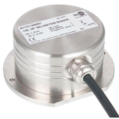
Inclination sensor
Description
Inclination sensors of model N131C for hazardous areas are designed with a flameproof enclosure and, for instance, intended for applications in offshore areas, for maritime applications and for the oil and gas industry.
The fields of application for these sensors are diverse. Due to the flameproof enclosure they fulfil the ignition protection type Ex d. Inclination sensors with flameproof enclosure are used in offshore plants for oil and gas extraction.
WIKA-data shet FO 59.02
Inclination sensor, model N131C
The sensors have a measuring range of up to 360° and offer an extraordinarily high accuracy and precision over the entire measuring range. Other measuring ranges, customer-specific as well, are also possible. The measured value resolution is 0.01°.
Special features
- Measuring range 0 ... 360°
- Relative linearity error < 0.1 % of FS over the entire measuring range
- Good damping behaviour, no influence due to gravity
- Resistant to seawater, IP67
- Easy retrofitting
| Model | N131C |
| Product family | N131 |
| Subcategory | Inclination sensor |
| Accuracy class | < 0.1 % of FS |
| Process temperature | −40…+80 °C |
| Output signal | 2 x 4 ... 20 mA (3-wire) |
| Cell material | Stainless steel |
| Ambient temperature | −40…+85 °C |
| IP rating | IP67 |
| Certifications | RoHSATEXIECExEMCCE |
| Explosion protection | Ex II 2G Ex d IIC T4 Gb (BVS 13 ATEX E 030 X)Ex II 2G Ex d IIC T4 Gb (BVS 13.0065X)ATEX: Ex II 2G Ex d IIC T4 Gb (BVS 13 ATEX E 030 X)IECEx: Ex II 2G Ex d IIC T4 Gb (BVS 13.0065X) |
| Cable length | 10 m |
| Datasheet languages | EN |
| Model N131C | |
|---|---|
| Measuring range ■ Standard ■ Optional | 0 …360° other measuring ranges possible |
| Relative linearity error d lin ■ < 100° ■ > 100° | < 0.1° < 0.1 %of FS |
| Relative reversibility error v | < 0.05 %of FS |
| Resolution | < 0.01° |
| Transverse inclination error ■ ≤ 10° ■ ≤ 45° | < 0.05 ° < 0.2 ° |
| Service temperature B T, G | -40 …+80 °C |
| Temperature effect on ■ the characteristic valueTK c ■ the zero signalTK 0 | 0.0016 %of FS/K 0.0016 %of FS/K |
| Electrical connection | Connection cable, 10 m, flying leads (others on request) |
| Output signal (rated characteristic value) C nom | 2 x 4 ... 20 mA(3-wire) |
| Voltage supply | DC 9 ...36V |
| Material of the measuring body | Stainless steel |
| Salt spray testing | DIN EN 60068-2-52 |
| Ingress protection (per IEC/EN 60529) | IP67 |
| EMC | 61326-1 IEC:2012, DIN EN 61000-4 Part 2, Part 3, Part 4, Part 6, Part 8, Part 9, Part 10; DIN ISO 7637 Part 2, DIN ISO 11452 Part 2, Part 4, Part 5; DIN EN 55025 Part 6.3, Part 6.4 |
| Certifications | ATEX and IECEx: acc. to EN60079-0:2012 und EN60079-1:2007 (Ex d) |
| Logo | Description | Region | |
|---|---|---|---|
| EU declaration of conformity ■ EMV-directive ■ RoHS-directive | European Union | ||
| ATEX directive Hazardous areas Ex II 2G Ex d IIC T4 Gb (BVS 13 ATEX E 030 X) | -40 °C <T amb < +85 °C | European Union | |
| IECEx Hazardous areas Ex II 2G Ex d IIC T4 Gb (BVS 13.0065X) | -40 °C <T amb < +85 °C | International |
| Wire | Output |
|---|---|
| 1 | UB+ (+24V) |
| 2 | S+ Signal 1 (4 ... 20 mA) |
| 3 | 0V/S- (electrical ground) |
| 4 | S+ signal 2 (4 ... 20 mA) |
Couldn't find the answer in the documentation? An engineer will reply within a business day.
Ask an engineer →