
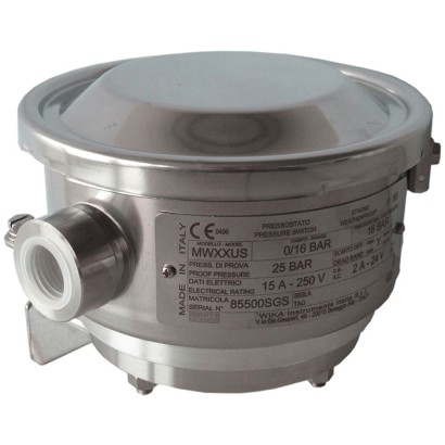
Diaphragm pressure switch
Description
These high-quality mechanical pressure switches have been developed especially for safety-critical applications. The great advantage of mechanical pressure switches is that no supply voltage is required for the switching process.
In production, the switches are traced by quality assurance software at every step and subsequently are 100 % tested. The robust switch enclosure from stainless steel 316L can withstand the rough and corrosive operating conditions of the process industry with working ranges of up to 600 bar. The pressure switch is fitted with 1 or 2 microswitches, which make it possible to switch an electrical load of up to
AC 250 V, 20 A directly.
For lower switching power ratings, such as for PLC applications, argon gas-filled microswitches with gold-plated contacts are available.
for further approvals, see page 6
Special features
- Case from 316L, IP66, NEMA 4X
- Setting ranges from 16 mbar to 600 bar, also all other equivalent vacuum or combined pressure and vacuum ranges
- Intrinsic safety Ex ia available
- 1 or 2 independent switch points, high switching power up to AC 250 V, 20 A
- Switch point repeatability < 1 %
| Model | MW |
| Subcategory | Diaphragm pressure switch |
| Pressure ranges | 0…100 mbar · 0…16 mbar · -100…0 mbar · -1…1.5 bar · -1…5 bar · -1…9 bar · -1…15 bar · 0…0.2 bar · 0…0.4 bar · 4…40 bar · 10…100 bar · 10…250 bar · 20…400 bar · 30…600 bar · 0…0.016 bar · 0…40 bar |
| Accuracy class | Set point repeatability ≤ 1 % of span |
| Accuracy standard | IEC 61298-2:2008 |
| Safety integrity level (SIL) | SIL 2-qualified or SIL 3-qualified per IEC 61508 / IEC 61513 |
| Process connection | M20x1.5¼ NPT, female thread½ NPT, female thread via adapter½ NPT, male thread via adapterG ¼, female thread via adapterG ½ A, male thread via adapterG ¼ A, male thread via adapterASME B16.5EN 1092-1¾ NPTG ½G ¾G 1/2 B1/2 NPTASME B16.5 Class 150/300/600EN 1092-1 PN10/401/4 NPT female1/2 NPT female (via adapter)1/2 NPT male (via adapter)G1/4 female (via adapter)G1/2A male (via adapter)G1/4A male (via adapter)ASME B16.5 flangeEN 1092-1 flange |
| Process temperature | −40…+85 °C |
| Electrical connection | Internal terminal block, cable gland (nickel-plated brass or stainless steel), MIL connector 7-pin DTL 5015 |
| Switching function | 1 or 2 independent switch points, SPDT or DPDT, fixed or adjustable dead band |
| Switching contacts | 2 |
| Case material | Stainless steel 316L |
| Wetted parts material | Stainless steel 316, Stainless steel 316L, PTFE, Monel, Hastelloy C276, FPM, NBR |
| Sealing material | FPM, NBR, PTFE, welded diaphragm element |
| Ambient temperature | −60…+85 °C |
| IP rating | IP66 |
| Weight | 1 kg |
| Certifications | RoHSNACE MR0175/ISO 15156NACE MR0103/ISO 17945EN 1854EN 12952EN 12953PEDLow voltage directiveUKCAEACEx UkraineCCCKCs-ECASCE |
| Explosion protection | ATEX: II 1 GDIECEx: Ex ia I Ma, Ex ia IIC T6/T42, Ex ia IIIC T85°C/T135°C2 DaNACE MR0175 / ISO 15156NACE MR0103 / ISO 17945EN 1854EN 12952EN 12953Ex iaEx ia I MaEx ia IIC T6/T4 GaEx ia IIIC T85℃/T135℃ Da IP66 |
| Datasheet languages | EN |
| Basic information | |
|---|---|
| Version | Diaphragm pressure switch |
| Special design feature | ■ Version for hazardous areas (Ex ia) ■ For oxygen, oil- and grease-free ■ Per NACE 1) MR0175 / ISO 15156, use in H₂S-containing environments in oil and gas production ■ Per NACE 1) MR0103 / ISO 17945, metals resistant to sulphide stress cracking ■ Version compliant with EN 1854, pressure sensing devices for gas burners and gas burning appliances ■ Version compliant with EN 12952 and EN 12953, limiting devices in water- tube and shell boilers ■ Drying of wetted parts ■ Offshore version ■ Tropical version (suitable for environments with increased air humidity) ■ Version for ammonia applications ■ Geothermal version ■ Low-temperature version to -60 °C ■ Assembled as a diaphragm seal system ■ Additional protection from stainless steel 316L or Hastelloy for setting ranges 2.5 ... 25 bar |
| Contact version | →See table 'Contact version' |
| Function | ■ 1 x SPDT (single pole double throw) ■ 2 x SPDT (single pole double throw) ■ 1 x DPDT (double pole double throw) The DPDT function is realised with 2 simultaneously triggering SPDT microswitches, within 0.2 %of span. |
| Dead band | ■ 1 or 2 contacts with fixed dead band ■ 1 or 2 contacts with adjustable dead band ■ 1 contact with fixed dead band and 1 contact with adjustable dead band |
| Dielectric strength | Safety class I (IEC 61298-2: 2008) |
| Switch enclosure | |
| Design | Case cover with bayonet lock, protection against unauthorised access by lead sealing possible. Laser-engraved product label from stainless steel. |
| Material | Stainless steel 316L |
| Mounting 2) | ■ Direct mounting ■ Wall bracket from stainless steel AISI 304 ■ Mounting bracket for 2" pipe mounting from stainless steel AISI 304 |
| Contact version | Electrical rating (resistive load) | Suitable for | ||
|---|---|---|---|---|
| AC | DC | Ex ia option | ||
| With fixed dead band | ||||
| UN | 1 x SPDT, silver | 250 V, 15 A | 24 V, 2 A, 125 V, 0.5 A, 220 V, 0.25 A | No |
| US | 1 x SPDT, silver, hermetically sealed, argon gas filling 1) | 250 V, 15 A | 24 V, 2 A, 220 V, 0.5 A | Yes |
| UO | 1 x SPDT, gold-plated, hermetically sealed, argon gas filling 1) | 125 V, 1 A | 24 V, 0.5 A | Yes |
| UG | 1 x SPDT, gold-plated | 125 V, 1 A | 24 V, 0.5 A | Yes |
| DN | 2 x SPDT or 1 x DPDT, silver | 250 V, 15 A | 24 V, 2 A, 125 V, 0.5 A, 220 V, 0.25 A | No |
| DS | 2 x SPDT or 1 x DPDT, silver, hermetically sealed, argon gas filling 1) | 250 V, 15 A | 24 V, 2 A, 220 V, 0.5 A | Yes |
| Contact version | Electrical rating (resistive load) | Suitable for Ex ia option | ||
|---|---|---|---|---|
| AC | DC | |||
| DO | 2 x SPDT, or 1 x DPDT gold-plated, hermetically sealed, argon gas filling 1) | 125 V, 1 A | 24 V, 0.5 A | Yes |
| DG | 2 x SPDT or 1 x DPDT, gold-plated | 125 V, 1 A | 24 V, 0.5 A | Yes |
| With adjustable dead band | ||||
| UR | 1 x SPDT, silver | 250 V, 20 A | 24 V, 2 A, 220 V, 0.5 A | Yes 2) |
| RR 3) | 2 x SPDT or 1 x DPDT, silver | 250 V, 15 A | 24 V, 2 A, 220 V, 0.5 A | Yes 2) |
| With fixed dead band and adjustable dead band | ||||
| DR 3) | 2 x SPDT, silver (1 x UN + 1 x UR) | 250 V, 15 A | 24 V, 2 A, 220 V, 0.5 A | Yes 2) |
| Sensor element | Model | Wetted parts | Permissible medium 1) | ||
|---|---|---|---|---|---|
| Sensor element | Process connection | temperature | |||
| Setting range 0 …16mbar to 0 …40bar | |||||
| XX 2) | Diaphragm element | MWB,MW | Stainless steel 316 3) | Stainless steel 316L | -30 ...+85 °C |
| TX | Diaphragm element | MWB,MW | Stainless steel 316 3) + PTFE 4) | Stainless steel 316L | -30 ...+85 °C |
| TT | Diaphragm element | MWB,MW | Stainless steel 316 3) + PTFE 4) | Stainless steel 316L + PTFE | -30 ...+85 °C |
| KK 2) | Diaphragm element | MWB,MW | Monel 5) | Monel | -30 ...+85 °C |
| KX 2) | Diaphragm element | MWB,MW | Monel 5) | Stainless steel 316L | -30 ...+85 °C |
| Setting range 4 …40bar to 30 …600 bar | |||||
| GXX 6) | Piston with welded diaphragm element | MWG | Hastelloy C276 | Stainless steel 316L | -40 ...+85 °C |
| HXX 7) | Piston with O-ring sealing from FPM | MWH | Stainless steel 316 | Stainless steel 316L | 0 ... 85 °C |
| Piston with O-ring sealing from NBR | MWH | Stainless steel 316 | Stainless steel 316L | -10 ...+85 °C |
View all (20)
| Set point repeatability | ≤ 1 %of span of setting range |
|---|---|
| Dead band | →See table 'Setting range' |
| Standard | Variant 1 | Variant 2 | Dead band | |||||
|---|---|---|---|---|---|---|---|---|
| Setting range (= working range) | Proof pressure | Working range | Proof pressure | Working range | Proof pressure | 1 contact, fixed | 2 contacts, fixed | 1 contact, adjustable |
| in mbar | in bar | in bar | in bar | in bar | in mbar | in mbar | in mbar | |
| 0 ... 16 | 250 | 0 ... 8 | 10 | -1 ... 8 1) | 10 | ≤ 2.0 | ≤ 2.8 | - |
| 0…25 | 250 | 0 ... 8 | 10 | -1 ... 8 1) | 10 | ≤ 2.0 | ≤ 3 | 8 …18 |
| 0…40 | 300 | 0…8 | 10 | -1 ... 8 1) | 10 | ≤ 2.6 | ≤ 3.4 | 8…20 |
| Standard | Variant 1 | Variant 2 | Dead band | |||||
|---|---|---|---|---|---|---|---|---|
| Setting range (= working range) | Proof pressure | Working range | Proof pressure | Working range | Proof pressure | 1 contact, fixed | 2 contacts, fixed | 1 contact, adjustable |
| in mbar | in bar | in bar | in bar | in bar | in mbar | in mbar | in mbar | |
| 0 ... 60 | 300 | 0…8 | 10 | -1 ... 8 1) | 10 | ≤ 3.0 | ≤ 4.2 | 12…25 |
| 0 ... 100 | 600 | 0…8 | 10 | -1 ... 8 1) | 10 | ≤ 3.6 | ≤ 5 | 17…40 |
| -16 ... 0 | -21 | -1…0 1) | 0.25 | - | - | ≤ 2.0 | ≤ 2.8 | - |
| -25 ... 0 | -35 | -1…0 1) | 0.25 | - | - | ≤ 2.0 | ≤ 3 | 8…18 |
| -40 ... 0 | -55 | -1…0 1) | 0.30 | - | - | ≤ 2.6 | ≤ 3.4 | 8…20 |
| -60 ... 0 | -90 | -1…0 1) | 0.30 | - | - | ≤ 3.0 | ≤ 4.2 | 12…25 |
| -100 ... 0 | -150 | -1…0 1) | 0.40 | - | - | ≤ 3.6 | ≤ 5 | 17…40 |
| -12.5 ... +12.5 | -25 / 250 | - | - | - | - | ≤ 2.0 | ≤ 3 | 8…18 |
| -30 ... +30 | -60 / 250 | - | - | - | - | ≤ 3.0 | ≤ 4.2 | 12…25 |
| -50 ... +50 | -100 / 250 | - | - | - | - | ≤ 3.6 | ≤ 5 | 17…40 |
| Standard | Variant 1 | Variant 2 | Dead band | |||||
|---|---|---|---|---|---|---|---|---|
| Setting range (= working range) | Proof pressure | Working range | Proof pressure | Working range | Proof pressure | 1 contact, fixed | 2 contacts, fixed | 1 contact, adjustable |
| in bar | in bar | in bar | in bar | in bar | in mbar | in mbar | in mbar | |
| 0 ... 0.2 | 0.4 | 0…32 | 40 | -1…32 1) | 40 | ≤ 10 | ≤ 13 | 30 …70 |
| 0 ... 0.4 | 1 | 0…32 | 40 | -1…32 1) | 40 | ≤ 15 | ≤ 20 | 40 ... 95 |
| -0.2 ... 0 | -0.3 | -1…0 1) | -1 | -1 ... 8 | 10 | ≤ 10 | ≤ 13 | 30…70 |
| -0.4 ... 0 | -0.6 | -1…0 1) | -1 | -1 ... 8 | 10 | ≤ 15 | ≤ 20 | 40…95 |
| -0.1 ... + 0.1 | -0.2 / 1 | - | - | - | - | ≤ 10 | ≤ 13 | 30…70 |
| -0.5 ... 0.5 | -1 / 4 | - | - | - | - | ≤ 15 | ≤ 50 | 75 ... 170 |
| -1 ... 0 | -1 | -1…8 | 10 | - | - | ≤ 15 | ≤ 50 | 75 …170 |
| -1 ... 1.5 | 2 | -1…8 | 10 | - | - | ≤ 48 | ≤ 67 | 200 …500 |
| -1 ... 5 | 12 | -1…32 | 40 | -1…80 | 100 2) | ≤ 100 | ≤ 160 | 400 …1,000 |
| -1 ... 9 | 20 | -1…32 | 40 | -1…80 | 100 2) | ≤ 100 | ≤ 180 | 600 …1,400 |
| -1 ... 15 | 25 | -1…32 | 40 | -1…80 | 100 2) | ≤ 150 | ≤ 250 | 1,000 …2,400 |
| 0 ... 1 | 4 | 0…32 | 40 | -1…32 | 40 | ≤ 15 | ≤ 50 | 75 …170 |
| 0 ... 1.2 | 4 | 0…32 | 40 | -1…32 | 40 | ≤ 15 | ≤ 50 | 75 …170 |
| 0 ... 2.5 | 5 | 0…32 | 40 | -1…80 | 100 2) | ≤ 48 | ≤ 67 | 200 …500 |
| 0 ... 6 | 12 | -1…32 | 40 | -1…80 | 100 2) | ≤ 100 | ≤ 160 | 400 …1,000 |
| 0 ... 10 | 20 | -1…32 | 40 | -1…80 | 100 2) | ≤ 100 | ≤ 180 | 600 …1,400 |
| 0 ... 16 | 25 | -1…32 | 40 | -1…80 | 100 2) | ≤ 150 | ≤ 250 | 1,000 …2,400 |
| 0 ... 25 | 40 | -1…32 | 40 | -1…80 | 100 2) | ≤ 300 | ≤ 450 | 1,700 …4,000 |
| 0 ... 40 | 50 | - | - | - | - | ≤ 400 | ≤ 800 | 2,200 …5,800 |
| Standard | Dead band | |||
|---|---|---|---|---|
| Setting range (= working range) | Proof pressure | 1 contact, fixed | 2 contacts, fixed | 1 contact, adjustable 1) |
| in bar | in bar | in bar | in bar | |
| 4 ... 40 | 100 | ≤ 3 | ≤ 4 | 5…11to8…15 |
| 10 ... 100 | 200 | ≤ 4 | ≤ 6 | 10 …22to15…28 |
| 10 ... 250 | 400 | ≤ 10 | ≤ 13 | 15 …38to27…55 |
| 20 ... 400 | 600 | ≤ 10 | ≤ 25 | 35 …80to43…90 |
| 30 ... 600 | 700 | ≤ 20 | ≤ 25 | 45 ... 105 to 83 ... 155 |
| Process connection | |
|---|---|
| Standard | ■ ANSI/ASME B1.20.1 ■ DIN EN ISO 228 ■ ASME B16.5 1) ■ EN 1092-1 1) |
| Size | |
| ANSI/ASME B1.20.1 | ■ ¼NPT, female thread ■ ½NPT, female thread via adapter ■ ½NPT, male thread via adapter |
| DIN EN ISO 228 | ■ G¼, female thread via adapter ■ G½A,male thread via adapter ■ G¼A,male thread via adapter |
| ASME B16.5 1) | Flange variant 'S' :With fixed stud bolts and included nuts and washers |
| EN 1092-1 1) | Flange variant 'T' :With through-holes and extension pipe →See dimensions from page 9 |
| Material (wetted) | |
| Sensor element | Depending on the selected sensor element →See table 'Sensor element' |
| Process connection | |
| Sealing | PTFE, FPM, NBR, without sealing: welded diaphragm element, depending on setting range and operating conditions. →See table 'Setting range' |
| Connection type | ■ Female thread½NPT ■ Female thread M20 x 1.5 ■ Female thread ¾NPT, G½, G¾, M20 x 1.5 ■ Cable gland non-armoured, nickel-plated brass ■ Cable gland non-armoured, stainless steel (AISI 304) ■ Cable gland armoured, nickel-plated brass ■ Cable gland armoured, stainless steel (AISI 304) ■ MIL connector, 7-pin, DTL 5015 |
|---|---|
| Wire cross-section | Use 0.5 ... 1.5 mm² (20 ... 16 AWG) for internal terminal block (also suitable for cable lugs). For the grounding cable connection to the protective conductor use max. 4 mm² for the internal and external screw. |
| Pin assignment | Connection details are given on the product label of the instrument. Connection terminals and the ground terminal are appropriately marked. |
| Medium temperature range | Depending on sensor element and sealing →See table 'Sensor element' |
|---|---|
| Ambient temperature range | T6/T85°C T a -60 ...+60 °C |
| T4/T135°C T a -60 ...+85 °C | |
| Non-Ex versions ■ -40 ...+85 °C ■ -60 ...+85 °C | |
| Ingress protection of the complete instrument | IP66 per EN/IEC 60529 (NEMA 4X) |
| Weight | Approx. 1.0 kg for modelsMW,MWG,MWH Approx. 1.5 kg for modelMWB |
| Description | Region |
|---|---|
| EU declaration of conformity | European Union |
| Pressure equipment directive PED, annex 1, category IV, safety accessories, module B + D | |
| Low voltage directive | |
| RoHS directive |
| Logo | Description | Region |
|---|---|---|
| EU declaration of conformity ATEX directive 1) IM1 | European Union | |
| II1GD IECEx 1) | International |
| Logo | Description | Region |
|---|---|---|
| UKCA | United Kingdom | |
| Pressure equipment (safety) regulations | ||
| Electrical equipment designed for use within certain voltage limits in support of the electrical equipment (safety) regulations | ||
| Restriction of hazardous substances (RoHS) regulations | ||
| Equipment and protective systems intended for use in potentially explosive atmospheres regulations 1) | ||
| EAC | Eurasian Economic Community | |
| Low voltage directive (applies only for non-Ex versions) | ||
| Hazardous areas 1) | ||
| Ex Ukraine Hazardous areas 1) | Ukraine | |
| CCC Hazardous areas 1) | China | |
| KCs Hazardous areas 1) | South Korea | |
| - | ECAS Hazardous areas 1) | United Arab Emirates |
| Logo | Description |
|---|---|
| SIL3 IEC 61508 / IEC 61511 | SIL 3-capable (option) Functional safety per IEC 61508 Contains performance level calculation per ISO 13849-1 |
| Certificates | ■ 2.2 test report per EN 10204 (e.g. state-of-the-art manufacturing, indication accuracy) ■ 3.1 inspection certificate per EN 10204 (e.g. indication accuracy) |
|---|---|
| Recommended calibration interval | 1 year (dependent on conditions of use) |
| Voltage | Ui = DC 30V |
|---|---|
| Current | Ii = 100mA |
| Power | P i = 750mW |
| Effective internal capacitance | Ci = 0 μF |
| Effective internal inductance | Li=0mH |
| DN | Class | Dimensions in mm[in] | ||||
|---|---|---|---|---|---|---|
| D | b | a | P | L | ||
| ½" | 150 | 110 [43,31] | 25 [9,84] | 60,3 [23,74] | 4 x M14 | 51 [20,08] |
| 300 | 110 [43,31] | 25 [9,84] | 66,7 [26,26] | 4 x M14 | 51 [20,08] | |
| ¾" | 150 | 110 [43,31] | 25 [9,84] | 69,8 [27,48] | 4 x M14 | 51 [20,08] |
| 1" | 150 | 110 [43,31] | 25 [9,84] | 79,4 [31,26] | 4 x M14 | 51 [20,08] |
| 300 | 150 [59,06] | 25 [9,84] | 88,9 [35] | 4 x M16 | 54 [21,26] | |
| 1 ½" | 150 | 150 [59,06] | 25 [9,84] | 98,4 [38,74] | 4 x M14 | 51 [20,08] |
| 300 | 150 [59,06] | 25 [9,84] | 114,3 [45] | 4 x M20 | 60 [23,62] | |
| 2" | 150 | 150 [59,06] | 25 [9,84] | 120,6 [47,48] | 4 x M16 | 54 [21,26] |
| 300 | 165 [64,96] | 22 [8,66] | 127 [50] | 8 x M16 | 54 [21,26] |
| DN | PN | Dimensions in mm[in] | ||||
|---|---|---|---|---|---|---|
| D | b | a | P | L | ||
| 15 | 10/40 | 110 [43,31] | 25 [9,84] | 65 [25,59] | 4 x M12 | 48 [18,9] |
| 20 | 10/40 | 110 [43,31] | 25 [9,84] | 75 [29,53] | 4 x M12 | 48 [18,9] |
| 25 | 10/40 | 110 [43,31] | 25 [9,84] | 85 [33,46] | 4 x M12 | 48 [18,9] |
| 40 | 10/40 | 150 [59,06] | 25 [9,84] | 110 [43,31] | 4 x M16 | 54 [21,26] |
Couldn't find the answer in the documentation? An engineer will reply within a business day.
Ask an engineer →