
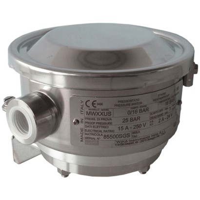
مفتاح ضغط بغشاء (Diaphragm pressure switch)
الوصف
تم تطوير مفاتيح الضغط الميكانيكية عالية الجودة هذه خصيصًا لتطبيقات تتطلب السلامة بدرجة حرجة. تتمثل الميزة الكبيرة لمفاتيح الضغط الميكانيكية في أنه لا يلزم وجود جهد إمداد لعملية التبديل.
في الإنتاج، يتم تتبع المفاتيح بواسطة برنامج ضمان الجودة في كل خطوة، ثم يتم اختبارها بنسبة 100 %. يمكن للهيكل القوي للمفتاح المصنوع من الفولاذ المقاوم للصدأ 316L أن يتحمل ظروف التشغيل القاسية والمسببة للتآكل في صناعة العمليات، ضمن مجالات عمل تصل إلى 600 bar. يتم تركيب مفتاح الضغط مع 1 أو 2 ميكروسويتش، مما يتيح تبديل حمل كهربائي حتى
AC 250 V، 20 A مباشرة.
بالنسبة لتصنيفات قدرة تبديل أقل، مثل تطبيقات PLC، تتوفر ميكروسويتشات مملوءة بغاز الأرجون مع نقاط تلامس مطلية بالذهب.
for further approvals, see page 6
المزايا
- علبة من 316L، IP66، NEMA 4X
- نطاقات ضبط من 16 mbar إلى 600 bar، وكذلك جميع نطاقات التفريغ أو الضغط والتفريغ المشترك المكافئة الأخرى
- متاح بأمان جوهري Ex ia
- نقطة أو نقطتا تبديل مستقلتان، قدرة تبديل عالية تصل إلى AC 250 V، 20 A
- تكرارية نقطة المفتاح < 1 %
الأسئلة والأجوبة
ما هو مدى الضغط الذي يغطيه مفتاح MW؟
تتراوح مجالات الضبط من 16 mbar إلى 600 bar، وتتوفر أيضًا جميع مجالات التفريغ المكافئة والمجالات المشتركة للضغط والتفريغ، مثل -100 … 0 mbar و-1 … +9 bar.
ما دقة نقطة التبديل؟
قابلية تكرار نقطة التبديل ≤ 1 % من المدى، وفقًا للمعيار IEC 61298-2:2008.
ما نوع الوصلات العملية المتاحة؟
تشمل M20x1.5، و1/4 NPT أنثوي، و1/2 NPT ذكري/أنثوي عبر محوّل، وG 1/4 A وG 1/2 A ذكري عبر محوّل، بالإضافة إلى شفاه ASME B16.5 Class 150/300/600 وEN 1092-1 PN10/40.
هل يناسب هذا المفتاح الوسائط العدوانية؟
نعم، فهو مناسب للوسائط الغازية والسائلة العدوانية وشديدة اللزوجة أو الملوثة، وتتوفر الأجزاء الملامسة للوسط من فولاذ مقاوم للصدأ 316/316L وPTFE وMonel وHastelloy C276.
ما حدود درجات الحرارة المسموح بها؟
درجة حرارة الوسط من -40 … +85 °C، ودرجة الحرارة المحيطة من -60 … +85 °C.
ما درجة الحماية من الدخول والبيئة؟
الهيكل من الفولاذ المقاوم للصدأ 316L بحماية IP66 وNEMA 4X، مما يجعله مناسبًا للظروف القاسية والمسببة للتآكل.
هل يتوفر اعتماد للمناطق الخطرة؟
نعم، تتوفر حماية جوهرية Ex ia مع شهادات ATEX: II 1 GD وIECEx: Ex ia I Ma, Ex ia IIC T6/T4 Ga, Ex ia IIIC T85°C/T135°C Da IP66.
ما الذي يميز طراز MW عن غيره؟
تم تطويره خصيصًا للتطبيقات الحرجة من ناحية السلامة، وهو مؤهل بمستوى سلامة SIL 2 أو SIL 3 وفق IEC 61508 / IEC 61513، ولا يحتاج إلى جهد إمداد للتبديل، ويوفر تبديل حمل مباشر حتى AC 250 V، 20 A مع 1 أو 2 نقطة تبديل مستقلة.
| الطراز | MW |
| النوع الفرعي | Diaphragm pressure switch |
| نطاق الضغط | 0…100 mbar · 0…16 mbar · -100…0 mbar · -1…1.5 bar · -1…5 bar · -1…9 bar · -1…15 bar · 0…0.2 bar · 0…0.4 bar · 4…40 bar · 10…100 bar · 10…250 bar · 20…400 bar · 30…600 bar · 0…0.016 bar · 0…40 bar |
| فئة الدقة | Set point repeatability ≤ 1 % of span |
| معيار الدقة | IEC 61298-2:2008 |
| مستوى السلامة الوظيفية (SIL) | SIL 2-qualified or SIL 3-qualified per IEC 61508 / IEC 61513 |
| وصلة العملية | M20x1.5¼ NPT, female thread½ NPT, female thread via adapter½ NPT, male thread via adapterG ¼, female thread via adapterG ½ A, male thread via adapterG ¼ A, male thread via adapterASME B16.5EN 1092-1¾ NPTG ½G ¾G 1/2 B1/2 NPTASME B16.5 Class 150/300/600EN 1092-1 PN10/401/4 NPT female1/2 NPT female (via adapter)1/2 NPT male (via adapter)G1/4 female (via adapter)G1/2A male (via adapter)G1/4A male (via adapter)ASME B16.5 flangeEN 1092-1 flange |
| درجة حرارة العملية | −40…+85 °C |
| وصلة كهربائية | Internal terminal block, cable gland (nickel-plated brass or stainless steel), MIL connector 7-pin DTL 5015 |
| وظيفة التبديل | 1 or 2 independent switch points, SPDT or DPDT, fixed or adjustable dead band |
| نقاط التبديل | 2 |
| مادة العلبة | Stainless steel 316L |
| مادة الأجزاء الملامسة | Stainless steel 316, Stainless steel 316L, PTFE, Monel, Hastelloy C276, FPM, NBR |
| مادة الإحكام | FPM, NBR, PTFE, welded diaphragm element |
| حرارة المحيط | −60…+85 °C |
| تصنيف IP | IP66 |
| الوزن | 1 kg |
| الشهادات | RoHSNACE MR0175/ISO 15156NACE MR0103/ISO 17945EN 1854EN 12952EN 12953PEDLow voltage directiveUKCAEACEx UkraineCCCKCs-ECASCE |
| حماية الانفجار | ATEX: II 1 GDIECEx: Ex ia I Ma, Ex ia IIC T6/T42, Ex ia IIIC T85°C/T135°C2 DaNACE MR0175 / ISO 15156NACE MR0103 / ISO 17945EN 1854EN 12952EN 12953Ex iaEx ia I MaEx ia IIC T6/T4 GaEx ia IIIC T85℃/T135℃ Da IP66 |
| لغات ورقة البيانات | EN |
| Basic information | |
|---|---|
| Version | Diaphragm pressure switch |
| Special design feature | ■ Version for hazardous areas (Ex ia) ■ For oxygen, oil- and grease-free ■ Per NACE 1) MR0175 / ISO 15156, use in H₂S-containing environments in oil and gas production ■ Per NACE 1) MR0103 / ISO 17945, metals resistant to sulphide stress cracking ■ Version compliant with EN 1854, pressure sensing devices for gas burners and gas burning appliances ■ Version compliant with EN 12952 and EN 12953, limiting devices in water- tube and shell boilers ■ Drying of wetted parts ■ Offshore version ■ Tropical version (suitable for environments with increased air humidity) ■ Version for ammonia applications ■ Geothermal version ■ Low-temperature version to -60 °C ■ Assembled as a diaphragm seal system ■ Additional protection from stainless steel 316L or Hastelloy for setting ranges 2.5 ... 25 bar |
| Contact version | →See table 'Contact version' |
| Function | ■ 1 x SPDT (single pole double throw) ■ 2 x SPDT (single pole double throw) ■ 1 x DPDT (double pole double throw) The DPDT function is realised with 2 simultaneously triggering SPDT microswitches, within 0.2 %of span. |
| Dead band | ■ 1 or 2 contacts with fixed dead band ■ 1 or 2 contacts with adjustable dead band ■ 1 contact with fixed dead band and 1 contact with adjustable dead band |
| Dielectric strength | Safety class I (IEC 61298-2: 2008) |
| Switch enclosure | |
| Design | Case cover with bayonet lock, protection against unauthorised access by lead sealing possible. Laser-engraved product label from stainless steel. |
| Material | Stainless steel 316L |
| Mounting 2) | ■ Direct mounting ■ Wall bracket from stainless steel AISI 304 ■ Mounting bracket for 2" pipe mounting from stainless steel AISI 304 |
| Contact version | Electrical rating (resistive load) | Suitable for | ||
|---|---|---|---|---|
| AC | DC | Ex ia option | ||
| With fixed dead band | ||||
| UN | 1 x SPDT, silver | 250 V, 15 A | 24 V, 2 A, 125 V, 0.5 A, 220 V, 0.25 A | No |
| US | 1 x SPDT, silver, hermetically sealed, argon gas filling 1) | 250 V, 15 A | 24 V, 2 A, 220 V, 0.5 A | Yes |
| UO | 1 x SPDT, gold-plated, hermetically sealed, argon gas filling 1) | 125 V, 1 A | 24 V, 0.5 A | Yes |
| UG | 1 x SPDT, gold-plated | 125 V, 1 A | 24 V, 0.5 A | Yes |
| DN | 2 x SPDT or 1 x DPDT, silver | 250 V, 15 A | 24 V, 2 A, 125 V, 0.5 A, 220 V, 0.25 A | No |
| DS | 2 x SPDT or 1 x DPDT, silver, hermetically sealed, argon gas filling 1) | 250 V, 15 A | 24 V, 2 A, 220 V, 0.5 A | Yes |
| Contact version | Electrical rating (resistive load) | Suitable for Ex ia option | ||
|---|---|---|---|---|
| AC | DC | |||
| DO | 2 x SPDT, or 1 x DPDT gold-plated, hermetically sealed, argon gas filling 1) | 125 V, 1 A | 24 V, 0.5 A | Yes |
| DG | 2 x SPDT or 1 x DPDT, gold-plated | 125 V, 1 A | 24 V, 0.5 A | Yes |
| With adjustable dead band | ||||
| UR | 1 x SPDT, silver | 250 V, 20 A | 24 V, 2 A, 220 V, 0.5 A | Yes 2) |
| RR 3) | 2 x SPDT or 1 x DPDT, silver | 250 V, 15 A | 24 V, 2 A, 220 V, 0.5 A | Yes 2) |
| With fixed dead band and adjustable dead band | ||||
| DR 3) | 2 x SPDT, silver (1 x UN + 1 x UR) | 250 V, 15 A | 24 V, 2 A, 220 V, 0.5 A | Yes 2) |
| Sensor element | Model | Wetted parts | Permissible medium 1) | ||
|---|---|---|---|---|---|
| Sensor element | Process connection | temperature | |||
| Setting range 0 …16mbar to 0 …40bar | |||||
| XX 2) | Diaphragm element | MWB,MW | Stainless steel 316 3) | Stainless steel 316L | -30 ...+85 °C |
| TX | Diaphragm element | MWB,MW | Stainless steel 316 3) + PTFE 4) | Stainless steel 316L | -30 ...+85 °C |
| TT | Diaphragm element | MWB,MW | Stainless steel 316 3) + PTFE 4) | Stainless steel 316L + PTFE | -30 ...+85 °C |
| KK 2) | Diaphragm element | MWB,MW | Monel 5) | Monel | -30 ...+85 °C |
| KX 2) | Diaphragm element | MWB,MW | Monel 5) | Stainless steel 316L | -30 ...+85 °C |
| Setting range 4 …40bar to 30 …600 bar | |||||
| GXX 6) | Piston with welded diaphragm element | MWG | Hastelloy C276 | Stainless steel 316L | -40 ...+85 °C |
| HXX 7) | Piston with O-ring sealing from FPM | MWH | Stainless steel 316 | Stainless steel 316L | 0 ... 85 °C |
| Piston with O-ring sealing from NBR | MWH | Stainless steel 316 | Stainless steel 316L | -10 ...+85 °C |
عرض الكل (20)
| Set point repeatability | ≤ 1 %of span of setting range |
|---|---|
| Dead band | →See table 'Setting range' |
| Standard | Variant 1 | Variant 2 | Dead band | |||||
|---|---|---|---|---|---|---|---|---|
| Setting range (= working range) | Proof pressure | Working range | Proof pressure | Working range | Proof pressure | 1 contact, fixed | 2 contacts, fixed | 1 contact, adjustable |
| in mbar | in bar | in bar | in bar | in bar | in mbar | in mbar | in mbar | |
| 0 ... 16 | 250 | 0 ... 8 | 10 | -1 ... 8 1) | 10 | ≤ 2.0 | ≤ 2.8 | - |
| 0…25 | 250 | 0 ... 8 | 10 | -1 ... 8 1) | 10 | ≤ 2.0 | ≤ 3 | 8 …18 |
| 0…40 | 300 | 0…8 | 10 | -1 ... 8 1) | 10 | ≤ 2.6 | ≤ 3.4 | 8…20 |
| Standard | Variant 1 | Variant 2 | Dead band | |||||
|---|---|---|---|---|---|---|---|---|
| Setting range (= working range) | Proof pressure | Working range | Proof pressure | Working range | Proof pressure | 1 contact, fixed | 2 contacts, fixed | 1 contact, adjustable |
| in mbar | in bar | in bar | in bar | in bar | in mbar | in mbar | in mbar | |
| 0 ... 60 | 300 | 0…8 | 10 | -1 ... 8 1) | 10 | ≤ 3.0 | ≤ 4.2 | 12…25 |
| 0 ... 100 | 600 | 0…8 | 10 | -1 ... 8 1) | 10 | ≤ 3.6 | ≤ 5 | 17…40 |
| -16 ... 0 | -21 | -1…0 1) | 0.25 | - | - | ≤ 2.0 | ≤ 2.8 | - |
| -25 ... 0 | -35 | -1…0 1) | 0.25 | - | - | ≤ 2.0 | ≤ 3 | 8…18 |
| -40 ... 0 | -55 | -1…0 1) | 0.30 | - | - | ≤ 2.6 | ≤ 3.4 | 8…20 |
| -60 ... 0 | -90 | -1…0 1) | 0.30 | - | - | ≤ 3.0 | ≤ 4.2 | 12…25 |
| -100 ... 0 | -150 | -1…0 1) | 0.40 | - | - | ≤ 3.6 | ≤ 5 | 17…40 |
| -12.5 ... +12.5 | -25 / 250 | - | - | - | - | ≤ 2.0 | ≤ 3 | 8…18 |
| -30 ... +30 | -60 / 250 | - | - | - | - | ≤ 3.0 | ≤ 4.2 | 12…25 |
| -50 ... +50 | -100 / 250 | - | - | - | - | ≤ 3.6 | ≤ 5 | 17…40 |
| Standard | Variant 1 | Variant 2 | Dead band | |||||
|---|---|---|---|---|---|---|---|---|
| Setting range (= working range) | Proof pressure | Working range | Proof pressure | Working range | Proof pressure | 1 contact, fixed | 2 contacts, fixed | 1 contact, adjustable |
| in bar | in bar | in bar | in bar | in bar | in mbar | in mbar | in mbar | |
| 0 ... 0.2 | 0.4 | 0…32 | 40 | -1…32 1) | 40 | ≤ 10 | ≤ 13 | 30 …70 |
| 0 ... 0.4 | 1 | 0…32 | 40 | -1…32 1) | 40 | ≤ 15 | ≤ 20 | 40 ... 95 |
| -0.2 ... 0 | -0.3 | -1…0 1) | -1 | -1 ... 8 | 10 | ≤ 10 | ≤ 13 | 30…70 |
| -0.4 ... 0 | -0.6 | -1…0 1) | -1 | -1 ... 8 | 10 | ≤ 15 | ≤ 20 | 40…95 |
| -0.1 ... + 0.1 | -0.2 / 1 | - | - | - | - | ≤ 10 | ≤ 13 | 30…70 |
| -0.5 ... 0.5 | -1 / 4 | - | - | - | - | ≤ 15 | ≤ 50 | 75 ... 170 |
| -1 ... 0 | -1 | -1…8 | 10 | - | - | ≤ 15 | ≤ 50 | 75 …170 |
| -1 ... 1.5 | 2 | -1…8 | 10 | - | - | ≤ 48 | ≤ 67 | 200 …500 |
| -1 ... 5 | 12 | -1…32 | 40 | -1…80 | 100 2) | ≤ 100 | ≤ 160 | 400 …1,000 |
| -1 ... 9 | 20 | -1…32 | 40 | -1…80 | 100 2) | ≤ 100 | ≤ 180 | 600 …1,400 |
| -1 ... 15 | 25 | -1…32 | 40 | -1…80 | 100 2) | ≤ 150 | ≤ 250 | 1,000 …2,400 |
| 0 ... 1 | 4 | 0…32 | 40 | -1…32 | 40 | ≤ 15 | ≤ 50 | 75 …170 |
| 0 ... 1.2 | 4 | 0…32 | 40 | -1…32 | 40 | ≤ 15 | ≤ 50 | 75 …170 |
| 0 ... 2.5 | 5 | 0…32 | 40 | -1…80 | 100 2) | ≤ 48 | ≤ 67 | 200 …500 |
| 0 ... 6 | 12 | -1…32 | 40 | -1…80 | 100 2) | ≤ 100 | ≤ 160 | 400 …1,000 |
| 0 ... 10 | 20 | -1…32 | 40 | -1…80 | 100 2) | ≤ 100 | ≤ 180 | 600 …1,400 |
| 0 ... 16 | 25 | -1…32 | 40 | -1…80 | 100 2) | ≤ 150 | ≤ 250 | 1,000 …2,400 |
| 0 ... 25 | 40 | -1…32 | 40 | -1…80 | 100 2) | ≤ 300 | ≤ 450 | 1,700 …4,000 |
| 0 ... 40 | 50 | - | - | - | - | ≤ 400 | ≤ 800 | 2,200 …5,800 |
| Standard | Dead band | |||
|---|---|---|---|---|
| Setting range (= working range) | Proof pressure | 1 contact, fixed | 2 contacts, fixed | 1 contact, adjustable 1) |
| in bar | in bar | in bar | in bar | |
| 4 ... 40 | 100 | ≤ 3 | ≤ 4 | 5…11to8…15 |
| 10 ... 100 | 200 | ≤ 4 | ≤ 6 | 10 …22to15…28 |
| 10 ... 250 | 400 | ≤ 10 | ≤ 13 | 15 …38to27…55 |
| 20 ... 400 | 600 | ≤ 10 | ≤ 25 | 35 …80to43…90 |
| 30 ... 600 | 700 | ≤ 20 | ≤ 25 | 45 ... 105 to 83 ... 155 |
| Process connection | |
|---|---|
| Standard | ■ ANSI/ASME B1.20.1 ■ DIN EN ISO 228 ■ ASME B16.5 1) ■ EN 1092-1 1) |
| Size | |
| ANSI/ASME B1.20.1 | ■ ¼NPT, female thread ■ ½NPT, female thread via adapter ■ ½NPT, male thread via adapter |
| DIN EN ISO 228 | ■ G¼, female thread via adapter ■ G½A,male thread via adapter ■ G¼A,male thread via adapter |
| ASME B16.5 1) | Flange variant 'S' :With fixed stud bolts and included nuts and washers |
| EN 1092-1 1) | Flange variant 'T' :With through-holes and extension pipe →See dimensions from page 9 |
| Material (wetted) | |
| Sensor element | Depending on the selected sensor element →See table 'Sensor element' |
| Process connection | |
| Sealing | PTFE, FPM, NBR, without sealing: welded diaphragm element, depending on setting range and operating conditions. →See table 'Setting range' |
| Connection type | ■ Female thread½NPT ■ Female thread M20 x 1.5 ■ Female thread ¾NPT, G½, G¾, M20 x 1.5 ■ Cable gland non-armoured, nickel-plated brass ■ Cable gland non-armoured, stainless steel (AISI 304) ■ Cable gland armoured, nickel-plated brass ■ Cable gland armoured, stainless steel (AISI 304) ■ MIL connector, 7-pin, DTL 5015 |
|---|---|
| Wire cross-section | Use 0.5 ... 1.5 mm² (20 ... 16 AWG) for internal terminal block (also suitable for cable lugs). For the grounding cable connection to the protective conductor use max. 4 mm² for the internal and external screw. |
| Pin assignment | Connection details are given on the product label of the instrument. Connection terminals and the ground terminal are appropriately marked. |
| Medium temperature range | Depending on sensor element and sealing →See table 'Sensor element' |
|---|---|
| Ambient temperature range | T6/T85°C T a -60 ...+60 °C |
| T4/T135°C T a -60 ...+85 °C | |
| Non-Ex versions ■ -40 ...+85 °C ■ -60 ...+85 °C | |
| Ingress protection of the complete instrument | IP66 per EN/IEC 60529 (NEMA 4X) |
| Weight | Approx. 1.0 kg for modelsMW,MWG,MWH Approx. 1.5 kg for modelMWB |
| Description | Region |
|---|---|
| EU declaration of conformity | European Union |
| Pressure equipment directive PED, annex 1, category IV, safety accessories, module B + D | |
| Low voltage directive | |
| RoHS directive |
| Logo | Description | Region |
|---|---|---|
| EU declaration of conformity ATEX directive 1) IM1 | European Union | |
| II1GD IECEx 1) | International |
| Logo | Description | Region |
|---|---|---|
| UKCA | United Kingdom | |
| Pressure equipment (safety) regulations | ||
| Electrical equipment designed for use within certain voltage limits in support of the electrical equipment (safety) regulations | ||
| Restriction of hazardous substances (RoHS) regulations | ||
| Equipment and protective systems intended for use in potentially explosive atmospheres regulations 1) | ||
| EAC | Eurasian Economic Community | |
| Low voltage directive (applies only for non-Ex versions) | ||
| Hazardous areas 1) | ||
| Ex Ukraine Hazardous areas 1) | Ukraine | |
| CCC Hazardous areas 1) | China | |
| KCs Hazardous areas 1) | South Korea | |
| - | ECAS Hazardous areas 1) | United Arab Emirates |
| Logo | Description |
|---|---|
| SIL3 IEC 61508 / IEC 61511 | SIL 3-capable (option) Functional safety per IEC 61508 Contains performance level calculation per ISO 13849-1 |
| Certificates | ■ 2.2 test report per EN 10204 (e.g. state-of-the-art manufacturing, indication accuracy) ■ 3.1 inspection certificate per EN 10204 (e.g. indication accuracy) |
|---|---|
| Recommended calibration interval | 1 year (dependent on conditions of use) |
| Voltage | Ui = DC 30V |
|---|---|
| Current | Ii = 100mA |
| Power | P i = 750mW |
| Effective internal capacitance | Ci = 0 μF |
| Effective internal inductance | Li=0mH |
| DN | Class | Dimensions in mm[in] | ||||
|---|---|---|---|---|---|---|
| D | b | a | P | L | ||
| ½" | 150 | 110 [43,31] | 25 [9,84] | 60,3 [23,74] | 4 x M14 | 51 [20,08] |
| 300 | 110 [43,31] | 25 [9,84] | 66,7 [26,26] | 4 x M14 | 51 [20,08] | |
| ¾" | 150 | 110 [43,31] | 25 [9,84] | 69,8 [27,48] | 4 x M14 | 51 [20,08] |
| 1" | 150 | 110 [43,31] | 25 [9,84] | 79,4 [31,26] | 4 x M14 | 51 [20,08] |
| 300 | 150 [59,06] | 25 [9,84] | 88,9 [35] | 4 x M16 | 54 [21,26] | |
| 1 ½" | 150 | 150 [59,06] | 25 [9,84] | 98,4 [38,74] | 4 x M14 | 51 [20,08] |
| 300 | 150 [59,06] | 25 [9,84] | 114,3 [45] | 4 x M20 | 60 [23,62] | |
| 2" | 150 | 150 [59,06] | 25 [9,84] | 120,6 [47,48] | 4 x M16 | 54 [21,26] |
| 300 | 165 [64,96] | 22 [8,66] | 127 [50] | 8 x M16 | 54 [21,26] |
| DN | PN | Dimensions in mm[in] | ||||
|---|---|---|---|---|---|---|
| D | b | a | P | L | ||
| 15 | 10/40 | 110 [43,31] | 25 [9,84] | 65 [25,59] | 4 x M12 | 48 [18,9] |
| 20 | 10/40 | 110 [43,31] | 25 [9,84] | 75 [29,53] | 4 x M12 | 48 [18,9] |
| 25 | 10/40 | 110 [43,31] | 25 [9,84] | 85 [33,46] | 4 x M12 | 48 [18,9] |
| 40 | 10/40 | 150 [59,06] | 25 [9,84] | 110 [43,31] | 4 x M16 | 54 [21,26] |
لم تجد الإجابة في الوثائق؟ سيرد المهندس خلال يوم عمل.
اسأل المهندس →