
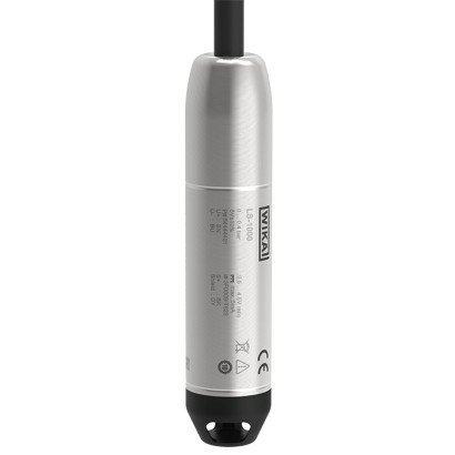
Submersible pressure sensor
Description
The model LS-1000 submersible pressure sensor continuously measures the level of liquid media in industrial environments. It records the level hydrostatically from 1 ... 10 m [3.28 ... 32.81 ft]. Optimum long-term stability ensures precise measured data and minimal signal drift. Hermetic leak tightness is ensured by the robust design and a specially developed cable with integrated strain relief. Due to its attractive pricing, the LS-1000 submersible pressure sensor is the ideal choice for OEM customers.
Special features
- Hydrostatic measurement of levels from 1 to 10 m [3.28 ... 32.81 ft]
- Permanently leak-tight
- Low total cost of ownership
- Certified for use in hazardous areas
- Low current consumption
Build a LS-1000 for your task
The article number is assembled automatically. If unsure — ask an engineer; we'll match the line's parameters.
- EX-Certificationwithout
- further EX-Certification 2without
- Accuracymax. measured error 1.0% per IEC 62628-1
- Unitbar
- Pressure typegauge
- Measuring range—
- Output signal4 ... 20 mA, 2-wire
- Electrical connection—
- Unit cable length—
- Cable length—
Finish your configuration
Select every option to submit the request.
| Model | LS-1000 |
| Product family | LS |
| Subcategory | submersible pressure sensor |
| Level ranges | 1…10 m |
| Process temperature | −10…+50 °C |
| Max process pressure | 2 bar |
| Measurement technology | hydrostatic |
| Output signal | 4 ... 20 mA · 0.5 ... 4.5 V ratiometric |
| Power supply | DC 8 ... 35 V (Ex: DC 14 ... 30 V), DC 5 V ± 10 % |
| Electrical connection | Cable, shielded, 7.5 mm diameter, 0.24 mm² wire cross-section |
| Wetted parts material | Stainless steel 316L, epoxy resin, PVDF, PVC, FEP, PVCFEP, PE (polyethylene) |
| Ambient temperature | −30…+80 °C |
| IP rating | IP68 |
| Weight | 0.2 kg |
| Certifications | CERoHSPressure Equipment DirectiveEMC Directive EN 61326China RoHS |
| Explosion protection | II 1G Ex ia IIC T6 ... T4 GaII 2G Ex ia IIC T6 ... T4 GbEx ia IIC T6 ... T4 GaEx ia IIC T6 ... T4 GbEx ia IIC T6 ... T4 GcII 1G Ex ia IIC T4 GaII 2G Ex ia IIC T4 GbEx ia IIC T4 GaEx ia IIC T4 GbEx ia IIC T4 Gc |
| Datasheet languages | EN |
| Accuracy specifications per IEC 62828-1 | Max. measured error ≤ ±0.5 %of span | Max. measured error ≤ ±1.0 %of span |
|---|---|---|
| Non-linearity per BFSL | ≤ ±0.25 %of span | ≤ ±0.5 %of span |
| Long-term stability | ≤ ±0.2 %of span/year | ≤ ±0.2 %of span/year |
| Accuracy | → See max. measured error per IEC 62828-1, above |
|---|---|
| Total probable error per IEC 62828-2 | → See table "Total probable error per IEC 62828-2" below |
| Non-repeatability per IEC 62828-1 | ≤ 0.1 %of span (0.2 %of span with measuring range 0 ... 100 mbar) |
| Reference conditions | Per IEC 62828-1 |
| Total probable error per IEC 62828-2 | Max. measured error ≤ ±0.5 %of span | Max. measured error ≤ ±1.0 %of span |
|---|---|---|
| Temperature range -10 ... +5 °C [+14 ... +41 °F] | ||
| Measuring range ≤ 0.1 bar | 2.0% | 2.2% |
| Measuring range < 0.4 bar [5.8 psi] | 1.3% | 1.6% |
| Measuring range ≥ 0.4 bar [5.8 psi] | 1.0% | 1.3% |
| Temperature range +5 …+35 °C [+41 ... +95 °F] | ||
| Measuring range ≤ 0.1 bar | 1.1% | 1.4% |
| Measuring range < 0.4 bar [5.8 psi] | 0.7% | 1.1% |
| Measuring range ≥ 0.4 bar [5.8 psi] | 0.6% | 1.1% |
| Temperature range +35 …+50 °C [+95 ... +122 °F] | ||
| Measuring range ≤ 0.1 bar | 2.0% | 2.2% |
| Measuring range < 0.4 bar [5.8 psi] | 1.3% | 1.6% |
| Measuring range ≥ 0.4 bar [5.8 psi] | 1.0% | 1.3% |
| bar | |
|---|---|
| 0 ... 0.1 | 0 ... 0.4 |
| 0 ... 0.16 | 0 ... 0.6 |
| 0 ... 0.25 | 0 ... 1 |
View all (20)
| 0 ... 5 | 0 ... 15 |
|---|---|
| 0 ... 10 | - |
| 0 ... 50 | 0 ... 250 |
|---|---|
| 0 ... 100 | 0 ... 400 |
| 0 ... 150 | - |
| 0 ... 1.25 | 0 ... 1.6 |
|---|---|
| 0 ... 1.4 | 0 ... 2 |
| Units | ■ bar ■ psi ■ inWC ■ mH₂O ■ mbar ■ kPa |
|---|---|
| Max. working pressure | → Corresponds to the upper measuring range value / measuring range full scale value → Any permanent operation above the maximum working pressure is not permissible |
| Overpressure limit per IEC 62828-2 | 1.5 times |
| Output signal | Current (2-wire) | Ratiometric |
|---|---|---|
| Signal type | 4 ...20mA | 0.5 ...4.5V |
| Load | ||
| Non-Ex version | ≤ (auxiliary power - 8 V) / 0.023 A - (cable length in mx0.0942 Ω/m) | ≥ 4.5 kΩ |
| Ex version | ≤ (auxiliary power - 14 V) / 0.023 A - (cable length in mx0.0942 Ω/m) | ≥ 4.5 kΩ |
| Signal clamping | ||
| Min. | 3.8mA | 0.45V |
| Max. | 20.5mA | 4.85V |
| Voltage supply | ||
| Auxiliary power | DC 8 ...35V (with Ex approval:DC 14 ... 30 V) | DC5V±10% |
| Current supply | Max.25mA | Max.5mA |
| Overvoltage resistance | DC 40V | DC 30V |
| Diagnostic function | ||
| Max. permissible vacuum/overpressure | 21.5mA | 5 %of auxiliary power |
| Max. permissible undertemperature/ overtemperature | 21.5mA | 5 %of auxiliary power |
| Sensor defect | 3.6mA | 3 %of auxiliary power |
| Sensor short-circuit | 3.6mA | 3 %of auxiliary power |
| EEPROM error | 3.6mA | 3 %of auxiliary power |
| Auxiliary power outside specification | < 3.0mA | < 2 %of auxiliary power |
| Dynamic behaviour | ||
| Switch-on time | ≤ 50 ms | ≤ 50 ms |
| Connection type | Cable, shielded | |
|---|---|---|
| Wire cross-section | 0.24 mm² [0.47 MCM] | |
| Cable diameter | 7.5 mm[0.3 in] | |
| Pin assignment | See "Pin assignment" auf Seite 4. | |
| Tension force of cable | 400 N | |
| Cable length | ■ 3m | ■ 10 ft |
| ■ 5m | ■ 20 ft | |
| ■ 10m | ■ 30 ft | |
| ■ 15m | ■ 40 ft | |
| ■ 20m | ■ 50 ft | |
| ■ 25m | ■ 75 ft | |
| ■ 30m | ■ 100 ft | |
| → Other cable lengths on request. |
| Lead resistance | 0.0942 Ω/m |
|---|---|
| Short-circuit resistance | S+ vs. U- |
| Reverse polarity protection | U+ vs. U- |
| Insulation voltage | DC 750V |
| Operating conditions | |
|---|---|
| Medium temperature limit | -10 ...+50 °C [+14 ...+122 °F] |
| Ambient temperature limit | -30 ...+80 °C [-22 ...+176 °F] |
| Storage temperature limit | -40 ...+80 °C [-40 ...+176 °F] |
| Operating altitude | ≤ 2,000 m[6,562 ft] |
| Pollution degree | 2 |
| Overvoltage category | I |
| Vibration resistance per IEC 60068-2-6 | 4g (25 - 100 Hz) |
| Shock resistance per IEC 60068-2-6 | 10g (6 ms) |
| Free fall per IEC 60068-2-31 | |
| Without packaging | 1 m[3.28 ft] |
| With individual packaging | 0.5 m[1.64 ft] |
| Mounting position | Calibrated in vertical mounting position with process connection facing down- wards. |
| Ingress protection (IP code) per IEC 60529 | IP68 (permanently, max. 15 m[49.2 ft]) |
| Service life | 10 million load cycles |
| Weight | |
| Submersible pressure sensor | Max. 200 g [0.441 lb] |
| Cable | ■ PVC approx. 75 g/m [2.64 lb/ft] ■ FEP approx. 90 g/m [3.17 lb/ft] |
| Packaging | Individual packaging |
|---|---|
| Instrument labelling | ■ WIKA product label, lasered (incl. marking of measuring locations with product label) ■ Customer-specific product label on request |
| Logo | Description | Region |
|---|---|---|
| EU declaration of conformity | European Union | |
| EMCDirective EN 61326 emission (group 1, class B) and immunity (industrial environments) | ||
| Pressure Equipment Directive | ||
| RoHS directive |
| Logo | Description | Region | |
|---|---|---|---|
| EU declaration of conformity | European Union | ||
| ATEX directive Hazardous areas 4 ...20mA | |||
| - Ex i Zone 0 gas | II 1G Ex ia IIC T6 ...T4 Ga II 2G Ex ia IIC T6 ...T4 Gb | ||
| Zone 1 gas 0.5 ...4.5V ratiometric | II 1G Ex ia IIC T4 Ga | ||
| - Ex i Zone 0 gas Zone 1 gas | II 2G Ex ia IIC T4 Gb | ||
| IECEx Hazardous areas 4 ...20mA | International | ||
| - Ex i Zone 0 gas | Ex ia IIC T6 ...T4 Ga | ||
| Zone 1 gas | Ex ia IIC T6 ...T4 Gb | ||
| Zone 2 gas 0.5 ...4.5V ratiometric Ex i | Ex ia IIC T6 ...T4 Gc | ||
| - Zone 0 gas | Ex ia IIC T4 Ga | ||
| Zone 1 gas | Ex ia IIC T4 Gb | ||
| Zone 2 gas | Ex ia IIC T4 Gc |
| Logo | Description |
|---|---|
| - | China RoHS directive |
| Certificates | ■ 2.2 test report per EN 10204 (e.g. state-of-the-art manufacturing, material proof, indica- tion accuracy) |
|---|
| Output signal | 4 ... 20 mA | 0.5 ... 4.5 V ratiometric |
|---|---|---|
| Max.medium temperature range | -10 °C ≤T m ≤ +50 °C | -10 °C ≤T m ≤ +50 °C |
| Connection values | ||
| Max. voltage U i | DC 30V | DC 12V |
| Max. current I i | 130mA | 400mA |
| Max. power P i (at the sensor) | 1,000mW | 550mW |
| Effective internal capacitance C i | 4.1 nF + 0.32 nF/m cable | 800 nF + 0.78 nF/m cable |
| Effective internal inductance L i | 0 µH + 1,77 µH/m cable | 0 µH + 1,77 µH/m cable |
| Output signal | Temperature class | Ambient temperature range |
|---|---|---|
| 4 ... 20 mA | T4 ...T1 | -30 °C …+80 °C |
| T6 | -30 °C …+60 °C | |
| 0.5 ... 4.5 V ratiometric | T4 ...T1 | -30 °C …+80 °C |
| Model | Description | Order number |
|---|---|---|
| Additional weight The additional weight increases the dead weight of the submersible pressure sensor. It simplifies the lowering in monitoring wells, narrow shafts and deep wells. It effectively reduces negative environmental influences of the medium (e.g. turbulent flows) on the measuring result. Stainless steel 316L, approx. 300 g [0.661 lb], length 115 mm[4.53 in] | 14131008 | |
| Cable strain relief clamp The cable strain relief clamp ensures easy and secure mechanical fastening of the submersible pressure sensor's cable. It serves to guide the cable to prevent mechani- cal damage and to reduce the action of tensile stresses. | 14052336 | |
| Cable socket The cable socket, with IP67 ingress protection and waterproof ventilation element, provides a moisture-free electrical termination for the submersible pressure sensor. It should be mounted in a dry environment, outside any shafts or vessels, or directly in the control cabinet. Not suitable for hazardous areas! | 14052339 | |
| Filter element The filter element prevents dirt and moisture from entering the capillary tube.The waterproof diaphragm also offers a reliable protection for the submersible pressure sensor in the harshest environments. | 14052344 |
Couldn't find the answer in the documentation? An engineer will reply within a business day.
Ask an engineer →20 standard articles of family LS
If you know the code — pick directly. If not — use the configurator in mode “01”.