
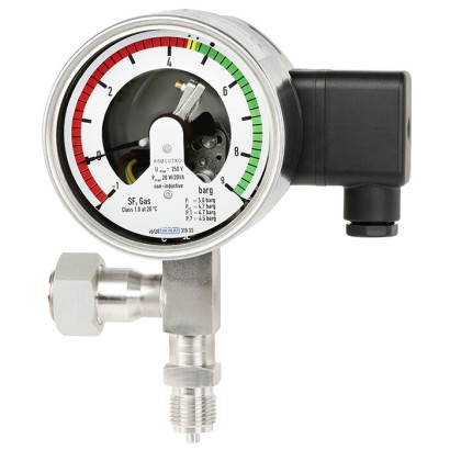
Gas density monitor
Description
The WIKA gas density measuring instruments provide reliable warnings against dangerously low gas levels, even under extreme ambient conditions. Electrical switch contacts warn the plant operator when the gas density drops below defined levels due to leakage.
Via the on-site indication, the pressure based on 20 °C [68 °F] can be read directly on the instrument.
With regard to switchgear safety, asset protection and environmental protection, it is common to perform functional checks on a regular basis. Article 5 of EU regulation no. 517/2014 on fluorinated greenhouse gases, provides for checking of the leakage detection system at least every 6 years if it contains > 22 kg [48.50 lb] SF₆ gas and the plant was commissioned after 01 January 2017.
Gas density monitor with calibration valve, model GDM-100
With the help of the firmly welded calibration valve, the gas density monitor can be shut off from the process and calibrated without having to disassemble it. This not only reduces maintenance time but also minimises the risks of SF₆ gas emissions and potential leakages during recommissioning.
When connecting a calibration system (e.g. model ACS-10 or model BCS-10) to the calibration valve, the gas density monitor is automatically disconnected from the gas compartment and a calibration can be performed. Following the calibration process, the calibration system can then be disconnected from the calibration valve and the connection to the gas compartment is reestablished automatically.
The calibration valve is also available as a retrofit solution for gas density monitors already installed in the field, as model GLTC-CV, and can be mounted between the gas compartment and gas density monitor.
Special features
- Local indication with switch contacts
- Temperature-compensated and hermetically sealed, therefore no influence of temperature fluctuations, height differences and atmospheric pressure fluctuations
- Compensation possible for gas mixtures
- Functional check or calibration possible without dismounting, in accordance with EU regulation no. 517/2014 on fluorinated greenhouse gases
- Test connection is welded to prevent leakage
| Model | GDM-100 |
| Product family | GDM |
| Subcategory | With calibration valve |
| Pressure ranges | 1.6…25 bar |
| Density reference temperature | 20 °C |
| Accuracy class | ±1 % at +20 °C, ±2.5 % at -20 ... +60 °C |
| Process connection | G ½ B per EN 837, lower mountG 1/2 B per EN 837, lower mount |
| Output signal | Magnetic snap-action contact |
| Switching contacts | 1 |
| Wetted parts material | Stainless steel |
| Ambient temperature | −20…+60 °C |
| IP rating | IP65 |
| Weight | 0.8 kg |
| Certifications | CERoHSEU declaration of conformityChina RoHS directive |
| Temperature compensation | Yes |
| Datasheet languages | EN |
| Nominal size | 100 |
|---|---|
| Window | ■ Laminated safety glass ■ Acrylic glass |
| Case | ■ Stainless steel, with gas filling ■ Stainless steel, with fill fluid Leakage rate: ≤ 1 · 10 -5 mbar · l / s |
| Calibration pressure P E | To customer specification |
| Measuring element | |
| Material | Stainless steel, welded |
| Leakage rate | ≤ 1 · 10 -8 mbar · l / s |
| Test method | Helium mass spectrometry |
| Movement | ■ Stainless steel ■ Bimetal link (temperature compensation) |
| Ring | Bayonet bezel, stainless steel, secured by means of 3 welding spots |
| Accuracy | ■ ±1 %at an ambient temperature of +20 °C [68 °F] ■ ±2.5 %at an ambient temperature of -20 …+60 °C [-4 ...+140 °F] and with calibration pressure in accordance with reference isochore (reference diagram KALI-Chemie AG, Hanover, prepared by Dr. Döring 1979) |
|---|
| Scale range | Vacuum and overpressure range with measuring span of 1.6 ... 25 bar [23.20 ... 362.59 psi] (at an ambient temperature of 20 °C [68 °F] and gaseous phase) |
|---|---|
| Dial | |
| Scale colour | Red, yellow, green |
| Material | Aluminium |
| Pointer | |
| Instrument pointer | Aluminium, black |
| Size | G½BperEN837, lower mount |
|---|---|
| Material (wetted) | Stainless steel, spanner flats 22 mm[0.86 in] |
View all (10)
| Operating temperature | ■ -20 ...+60 °C [-4 ...+140 °F], gaseous phase ■ -40 ...+60 °C [-40 ...+140 °F] |
|---|---|
| Storage temperature range | -50 ...+60 °C [-58 ...+140 °F] |
| Relative humidity, condensation | ≤ 90 %r.h. (non-condensing) |
| Ingress protection | IP65 per IEC/EN 60529 |
| Weight in kg | ■ With gas filling: approx. 0.8 kg [1.76 lb] ■ With fill fluid: approx. 1.2 kg [2.64 lb] |
| Electrical connection | |
|---|---|
| Connection type | Cable socket with compression fitting M20 x 1.5 |
| Wire cross-section | Wire cross-section max. 2.5 mm² |
| Switch contact | ■ 1 magnetic snap-action contact ■ 2 magnetic snap-action contacts ■ 3 magnetic snap-action contacts |
| Switching direction | ■ Falling pressure ■ Rising pressure |
| Switching function at nominal pressure | ■ Normally open ■ Normally closed ■ Change-over contact (max. 2 switch points) |
| Circuit | ■ Galvanically connected (not for change-over contact) ■ Galvanically isolated |
| Switching accuracy | |
| Switch point = calibration pressure P E | See accuracy specifications |
| Switch point ≠ calibration pressure P E | Parallel to the reference isochore of the calibration pressure |
| Max. switching voltage | AC 250V |
| Switching power | ■ With gas filling:30W/ 50 VA, max. 1 A ■ With fill fluid:20W/ 20 VA, max. 1 A |
| Material of switch contacts | 80 %Ag/ 20 %Ni, gold-plated |
| Further information on magnetic snap-action contacts in data sheet AC 08.01 | |
| High-voltage test 100% | 2 kV, 50 Hz, 1 s |
| Logo | Description | Country |
|---|---|---|
| EU declaration of conformity | European Union |
| Logo | Description |
|---|---|
| - | China RoHS directive |
| Model | Description | Order number |
|---|---|---|
| Calibration valve for retrofitting to gas density monitors and other leakage detection systems already installed in the field, model GLTC-CV Any arrangement of the test valve possible Other process connections on request → SeeWIKA data sheet SP 61.16 | 14484687 | |
| Adapter from test connection (M26 x 1.5) to quick coupling | 14146937 | |
| Protective cap for test connection (M26 x 1.5) | 14193772 | |
| Calibration system for gas density instrumentation → SeeWIKA data sheet SP 60.08 | 14424241 |
| Description | Order number |
|---|---|
| Adapter from test connection (M26 x 1,5) to RECTUS quick coupling | 14146937 |
| Tool set to actuate the shut-off valve | 14232498 |
| Wrench socket for shut-off valve (4KT 5,2 mm1/) | 14146708 |
| Protection cap for test connection (M26 x 1,5) | 14193772 |
| Protection cap for shut-off valve (silicone) | 14183253 |
Couldn't find the answer in the documentation? An engineer will reply within a business day.
Ask an engineer →1 standard articles of family GDM
If you know the code — pick directly. If not — use the configurator in mode “01”.