
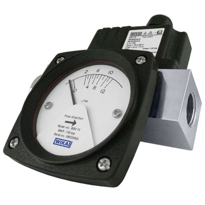
Flow switch, mechanical
Description
The model FSM-BSV flow switch is designed for flow indication and monitoring of liquids in cooling circuits and systems of welding machinery, laser and pipeline systems, dosing systems, pumps, compressors, hydraulic systems, high-pressure plants and many more.
Based on the piston working principle, a float (piston), with its integrated magnet, is moved by the medium in the direction of the flow within a cylindrical slotted nozzle or measuring tube. When the switch contact position is reached, the float stops.
Special features
- High switching accuracy and functional safety
- Switch point repeatability of ±5 %
- Large switching range, low switch hysteresis
- Viscosity-compensated models available
- Continuous switch point setting by the user
Build a FSM-BSV for your task
The article number is assembled automatically. If unsure — ask an engineer; we'll match the line's parameters.
- Line size8 DN
- Flow Range0,3 -3 lpm, maximum working flow 6 lpm
- Process connections size1/4"
- Thread typeBSP-F
- Sensor housingNickel plated brass
- DialWith dial
- Switching function1 x SPDT
- Area classificationStandard for safe area
- Electrical connection—
- Switch enclosureGF Nylon
- Maximum operating pressure100 bar
Finish your configuration
Select every option to submit the request.
| Model | FSM-BSV |
| Product family | FSM |
| Subcategory | Mechanical flow switch |
| Flow ranges | 0.3…3 L/min · 0.5…5 L/min · 1…8 L/min · 2…12 L/min · 5…25 L/min · 7…35 L/min · 10…40 L/min · 12…40 L/min · 20…60 L/min · 25…60 L/min · 30…90 L/min · 40…110 L/min · 50…150 L/min · 60…230 L/min · 75…175 L/min · 90…220 L/min · 100…200 L/min · 180…330 L/min · 330…500 L/min · 40…85 L/min |
| Pipe diameter | 80 mm |
| Accuracy | 5 % |
| Process connection | 1 NPT, female thread2 NPT, female thread1 BSP, female thread2 BSP, female thread3 BSP, female thread¼ NPT, female thread⅜ NPT, female thread½ NPT, female thread¾ NPT, female thread1 ¼ NPT, female thread1 ½ NPT, female thread2 ½ NPT, female thread¼ BSP, female thread⅜ BSP, female thread½ BSP, female thread¾ BSP, female thread1 ¼ BSP, female thread1 ½ BSP, female thread2 ½ BSP, female thread1/4 NPT, female thread3/8 NPT, female thread1/2 NPT, female thread3/4 NPT, female thread1 1/4 NPT, female thread1 1/2 NPT, female thread2 1/2 NPT, female thread1/4 BSP, female thread3/8 BSP, female thread1/2 BSP, female thread3/4 BSP, female thread1 1/4 BSP, female thread1 1/2 BSP, female thread2 1/2 BSP, female thread |
| Process temperature | −20…+110 °C |
| Measurement technology | variable_area |
| Output signal | 1 x SPDT · 2 x SPDT |
| Wetted parts material | Brass, nickel-plated, Stainless steel 316L, Barium ferrite magnet, Stainless steel 304 with PTFE-coated spring, Barium ferrite magnet (BaFe-magnet), Stainless steel 304, PTFE-coated spring |
| Ambient temperature | −20…+80 °C |
| IP rating | IP65 |
| Weight | 2.5 kg |
| Certifications | CERoHSLow Voltage Directive |
| Datasheet languages | EN |
| Setting range | ||
|---|---|---|
| DN 10 | 0.3 ... 3 | 6 |
| 0.5 ... 5 | 10 | |
| 1 ... 8 | 16 | |
| 2 ... 12 | 24 | |
| DN 15 | 0.3 ... 3 | 6 |
| 0.5 ... 5 | 10 | |
| 1 ... 8 | 16 | |
| 2 ... 12 | 24 | |
| 5 ... 25 | 50 | |
| 7 ... 35 | 70 | |
| 12 ... 40 | 80 | |
| DN 20 | 0.3 ... 3 | 6 |
| 0.5 ... 5 | 10 | |
| 1 ... 8 | 16 | |
| 2 ... 12 | 24 | |
| 5 ... 25 | 50 | |
| 7 ... 35 | 70 | |
| 10 ... 40 | 80 | |
| 25 ... 60 | 120 | |
| 40 ... 85 | 170 | |
| DN 25 | 0.3 ... 3 | 6 |
| 0.5 ... 5 | 10 | |
| 2 ... 12 | 24 | |
| 5 ... 25 | 50 | |
| 7 ... 35 | 70 | |
| 12 ... 40 | 80 | |
| 20 ... 60 | 120 | |
| DN 32 | 25 ... 60 | 120 |
| 30 ... 90 | 180 | |
| 40 ... 110 | 220 | |
| 50 ... 150 | 300 | |
| DN 40 | 40 ... 110 | 220 |
| 50 ... 150 | 300 | |
| 60 ... 230 | 460 | |
| DN 50 | 50 ... 150 | 300 |
| 75 ... 175 | 350 | |
| 90 ... 220 | 440 | |
| DN 65 | 100 ... 200 | 400 |
| 180 ... 330 | 660 | |
| 180 ... | 660 | |
| 330 ... 500 | 1,000 | |
| DN 80 | 330 |
| Process connection | |
|---|---|
| Standard | ■ ANSI/ASME B1.20.1 ■ DIN ISO 228 |
| Thread size | |
| ANSI/ASME B1.20.1 | ■ ¼NPT, female thread ■ ⅜NPT, female thread ■ ½NPT, female thread ■ ¾NPT, female thread ■ 1 NPT, female thread ■ 1 ¼NPT, female thread ■ 1 ½NPT, female thread ■ 2 NPT, female thread ■ 2 ½NPT, female thread |
| DIN ISO 228 | ■ ¼BSP, female thread ■ ⅜BSP, female thread ■ ½BSP, female thread ■ ¾BSP, female thread ■ 1 BSP, female thread ■ 1 ¼BSP, female thread ■ 1 ½BSP, female thread ■ 2 BSP, female thread ■ 2 ½BSP, female thread ■ 3 BSP, female thread |
| Sealing | EPDM |
| Type of mounting | ■ Horizontal in-line pipe mounting ■ Vertical in-line pipe mounting (flow direction bottom to top) |
| Switching function | ■ 1 x SPDT (single pole double throw) ■ 2 x SPDT (single pole double throw) for version without dial only |
|---|---|
| Setting range | → See table 'Setting range' |
| Hysteresis | ≤ 45 %of full scale value |
| Minimum load | → See table 'NS' |
| Connection type | ■ DIN (DIN EN 175 301-803-A) ■ M12 connector (male, back mount, straight) |
|---|---|
| Pin assignment | The pin assignment is given on the product label on the instrument. Connection termi- nals and the ground terminal are appropriately marked. |
| Ingress protection per IEC 60529 | IP65 |
View all (14)
| Place of use | Indoor applications |
|---|---|
| Altitude | Up to 2,000m |
| Medium temperature range | -20 ... 110° C [-4 ... 230 °F] → Liquid media with the property of changing the volume during solidification can dam- age the measuring system (e.g. water if it falls below the freezing point). |
| Ambient temperature range | -20 ...+80 °C [-4 ...+176 °F] |
| Storage temperature range | -20 ...+80 °C [-4 ...+176 °F] |
| Permissible media | ■ Water ■ Oil (viscosity of 30 ... 600 cSt) |
| Mounting position | ■ Horizontal ■ Vertical |
| Permissible pollution degree | 2 |
| Overvoltage category | II |
| Weight | Approx. 2 ... 3 kg [4.4 ... 6.6 lb] (depending on model) |
| AC current | DC current | ||||||||
|---|---|---|---|---|---|---|---|---|---|
| Resistive load | Inductive load | Resistive load | Inductive load | ||||||
| 125 V | 250 V | 125 V | 250 V | 30 V | 125 V | 250V | 30 V | 125 V | 250V |
| 5 A | 3 A | 3 A | 2 A | 4 A | 0.4 A | 0.2 A | 3 A | 0.4 A | 0.2 A |
| Logo | Description | Region |
|---|---|---|
| EU declaration of conformity | European Union | |
| LowVoltage Directive | ||
| RoHS directive |
| NS | Process connection NPT/BSP | C | D | h | A | b | L | a |
|---|---|---|---|---|---|---|---|---|
| DN 8 | ¼ " | 122 [4.80] | 36 [1.417] | 20.5 [0.807] | 54 [2.126] | 78 [3.071] | 83.5 [3.287] | 62.3 [2.453] |
| DN 10 | ⅜ " | |||||||
| DN 15 | ½ " | |||||||
| DN 20 | ¾ " | |||||||
| DN 25 | 1 " | 159 [6.26] | 40 [1.575] | 22.5 [0.886] | 58 [2.283] | 84 [3.307] | - | - |
| NS | Process connection NPT/BSP | C | D | h | A | e | L | a |
|---|---|---|---|---|---|---|---|---|
| DN 8 | ¼ " | 122 [4.80] | 36 [1.417] | 20.5 [0.807] | 54 [2.126] | 122 [4.80] | 83.5 [3.287] | 62.3 [2.453] |
| DN 10 | ⅜ " | |||||||
| DN 15 | ½ " | |||||||
| DN 20 | ¾ " | |||||||
| DN 25 | 1 " | 159 [6.26] | 40 [1.575] | 22.5 [0.886] | 58 [2.283] | 124 [4.882] | - | - |
| NS | Process connection NPT/BSP | C | D | b2 |
|---|---|---|---|---|
| DN 8 | ¼ " | 122 [4.80] | 36 [1.417] | 59.5 [2.343] |
| DN 10 | ⅜ " | |||
| DN 15 | ½ " | |||
| DN 20 | ¾ " | |||
| DN 25 | 1 " | 159 [6, 26] | 40 [1.575] |
| NS | Process connection NPT/BSP | C | D | b2 |
|---|---|---|---|---|
| DN 8 | ¼ " | 122 [4.80] | 36 [1.417] | 59.5 [2.343] |
| DN 10 | ⅜ " | |||
| DN 15 | ½ " | |||
| DN 20 | ¾ " | |||
| DN 25 | 1 " | 159 [6.26] | 40 [1.575] |
| NS | Process connection | C | D | b2 | |
|---|---|---|---|---|---|
| NPT | BSP | ||||
| DN 32 | 1¼ " | 1¼ " | 128 [5.039] | 70 [2.756] | 76 [2.992] |
| DN 40 | 1 ½" | 1 ½" | |||
| DN 50 | 2 " | 2 " | 220 [8.661] | 75 [2.953] | 76.5 [3.012] |
| DN 65 | 2 ½" | 2 ½" | 90 [3.543] | 76 [2.992] | |
| DN 80 | - | 3" | 114 [4.488] | 91 [3.583] |
| NS | Process connection | C | D | b2 | |
|---|---|---|---|---|---|
| NPT | BSP | ||||
| DN 32 | 1¼ " | 1¼ " | 128 [5.039] | 70 [2.756] | 76 [2.992] |
| DN 40 | 1 ½" | 1 ½" | |||
| DN 50 | 2 " | 2 " | 220 [8.661] | 75 [2.953] | 76.5 [3.012] |
| DN 65 | 2 ½" | 2 ½" | 90 [3.543] | 76 [2.992] | |
| DN 80 | - | 3" | 114 [4.488] | 91 [3.583] |
| NS | G | L | |
|---|---|---|---|
| NPT | BSP | ||
| DN 8 | ¼ " | ¼ " | 18 [0.71] |
| DN 10 | ⅜ " | ⅜ " | |
| DN 15 | ½ " | ½ " | 16 [0.63] |
| DN 20 | ¾ " | ¾ " | |
| DN 25 | 1 " | 1 " | 20 |
| DN 32 | 1¼ " | 1¼ " | 22 |
| DN 40 | 1 ½" | 1 ½" | |
| DN 50 | 2 " | 2 " | 35 [1.38] |
| DN 65 | 2 ½" | 2 ½" | |
| DN 80 | - | 3" | 40 [1.57] |
Couldn't find the answer in the documentation? An engineer will reply within a business day.
Ask an engineer →2 standard articles of family FSM
If you know the code — pick directly. If not — use the configurator in mode “01”.