
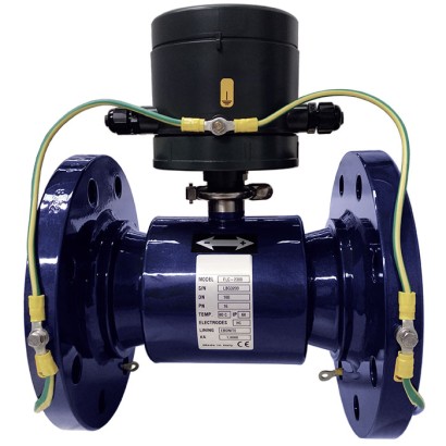
Electromagnetic flow meter
Description
Electromagnetic flow meters are based on the Faraday principle, by which a conductor which traverses a magnetic field generates a potential oriented perpendicular to that field. The flow tube is enclosed by two flanges and also by two coils. The magnetic field which is generated by the electric current running through the coils induces a potential difference in the electrodes that is proportional to the flow being measured.
A WIKA signal converter, either attached directly to the instrument or separated from it (e.g. model FLC-608), generates the current to supply the magnetic coil, detects the potential difference between the electrodes, processes the signal to calculate the flow and manages communication with the external control systems.
Electromagnetic flow meters have no moving internal parts and thus have a very low pressure loss. OIML R-49 permits a maximum pressure loss of 630 mbar [9. 14 psi] with a flow velocity of approx. 8 m/s.
Flow meter, model FLC-2300
The model FLC-2300 flow tube has a conical profile, through which the flow is accelerated and the signal to the electrodes is amplified. Due to this special feature, the model FLC-2300 flow meter has a pressure loss of less than 250 mbar [3,63 psi] at a velocity of 8 m/s.
For flow velocities of less than 1 m/s, the pressure loss is always less than 10 mbar [0,15 psi].
The conical profile of the flow tube enables a flexible operation in numerous areas of application, since no upstream or downstream runs are required.
The maintenance-free measuring instrument is suitable for use in pits, for underground applications and also for permanent immersion under water.
Very small flow volumes can be measured precisely and repeatedly, even in difficult applications with solid components in the medium.
Special features
- No upstream or downstream runs required
- Approved for custody transfer (MID MI-001, OIML R49)
- Accurate low flow measurement
- Case from stainless steel with ebonite lining
| Model | FLC-2300 |
| Product family | FLC |
| Subcategory | Electromagnetic flow meter |
| Flow ranges | 0.125…31.25 m³/h · 0.2…50 m³/h · 0.315…78.75 m³/h · 0.5…125 m³/h · 0.8…200 m³/h · 1.25…312.5 m³/h · 3.15…787.5 m³/h · 5…1250 m³/h · 8…1250 m³/h · 0.125…25 m³/h · 0.2…40 m³/h · 0.315…63 m³/h · 0.5…100 m³/h · 0.8…160 m³/h · 1.25…250 m³/h · 3.15…630 m³/h · 5…1000 m³/h · 8…1000 m³/h |
| Pipe diameter | 300 mm |
| Accuracy | 0.2 % |
| Process connection | ANSI 150EN 1092-1 (PN 16)AS 2129 (table D - E - F)AS 4087 (PN 16, PN 21)KS 10K |
| Process temperature | −40…+80 °C |
| Max process pressure | 16 bar |
| Measurement technology | magnetic |
| Wetted parts material | SS304, SS316, SS316L, Titanium, Tantalum, Platinum, Hard rubber (ebonite), Hastelloy C, HastelloyC® |
| Ambient temperature | −40…+80 °C |
| IP rating | IP68 |
| Certifications | CEOIML R49MID MI-001EMC EN 61326Low Voltage Directive |
| Explosion protection | ATEX (option for separated version)IECEx (option for separated version) |
| Datasheet languages | EN |
| mm | 50 | 65 | 80 | 100 | 125 | 150 | 200 | 250 | 300 |
|---|---|---|---|---|---|---|---|---|---|
| in | 2 | 2.5 | 3 | 4 | 5 | 6 | 8 | 10 | 12 |
| Materials | |
|---|---|
| Flow tube | ■ SS304 (standard) ■ SS316 |
| Flanges | ■ Carbon steel (S235JR - 1.0037) (standard) ■ SS304 ■ SS316 |
| Electrodes | ■ SS316L (standard) ■ Hastelloy C ® ■ Titanium ■ Tantalum ■ Platinum |
| Flow tube lining | Hard rubber (ebonite) 1) |
| Painting of sensor housing and flange | Acrylic paint (painting for class C4 environments on request) |
| Pressure loss class | |
| DN ≤ 80 | ΔP25 (< 0.25 bar [3,6 psi]) |
| DN ≥ 80 | ΔP40 (< 0.4 bar [5,8 psi]) |
| Medium temperature | -40 ...+80 °C [-40 ...+176 °F] |
| Electrodes | ■ Three ■ Fourth electrode as an empty-pipe alarm, activation and deactivation via software |
| Available flange standards | EN 1092-1 (PN 16), ANSI 150, AS 2129 (table D - E - F), AS 4087 (PN 16, PN 21), KS 10K, others on request |
| Installation requirements | U0, D0 |
| Ingress protection per EN 60529 | IP68 (continuous immersion to 1.5 m[4,9 ft]) |
| Compatible signal converters | ■ Model FLC-608A/B/R/P/I ■ Model FLC-406 |
| Electrical connection | Cable gland M20 x 1.5, terminal block and sealing resin |
| Sensor diameter | Flow rate [m³/h] | Ratio R Q3/ Q1 | ||||
|---|---|---|---|---|---|---|
| Minimum flow Q1 | Transition flow Q2 | Q 0.4% | Permanent flow Q3 | Overload flow Q4 | ||
| DN 50 [2"] | 0.125 | 0.2 | 3.5 | 25 | 31.25 | 200 |
| DN 65 [2.5"] | 0.2 | 0.32 | 6 | 40 | 50 | 200 |
| DN 80 [3"] | 0.315 | 0.5 | 9 | 63 | 78.75 | 200 |
| DN 100 [4"] | 0.5 | 0.8 | 14 | 100 | 125 | 200 |
| DN 125 [5"] | 0.8 | 1.28 | 22 | 160 | 200 | 200 |
| DN 150 [6"] | 1.25 | 2 | 32 | 250 | 312.5 | 200 |
| DN 200 [8"] | 3.15 | 5.04 | 57 | 630 | 787.5 | 200 |
| DN 250 [10"] | 5 | 8 | 90 | 1,000 | 1,250 | 200 |
| DN 300 [12"] | 8 | 12.5 | 128 | 1,000 | 1,250 | 125 |
| DN | H | H1 |
|---|---|---|
| DN 50 [2"] | 62 | 187 |
| DN 65 [2.5"] | 62 | 187 |
| DN 80 [3"] | 71 | 196 |
| DN 100 [4"] | 79 | 204 |
| DN 125 [5"] | 106 | 231 |
| DN 150 [6"] | 101 | 226 |
| DN 200 [8"] | 147 | 272 |
| DN 250 [10"] | 176 | 301 |
| DN 300 [12"] | 207 | 332 |
View all (12)
| DN | H H1 |
|---|---|
| DN 50 [2"] | 62 188 |
| DN 65 [2.5"] | 62 188 |
| DN 80 [3"] | 71 197 |
| DN 100 [4"] | 79 205 |
| DN 125 [5"] | 106 232 |
| DN 150 [6"] | 101 227 |
| DN 200 [8"] | 147 273 |
| DN 250 [10"] | 176 302 |
| DN 300 [12"] | 207 333 |
| Model FLC-608 A/B/R | ||
|---|---|---|
| DN | H | H1 |
| DN 50 [2"] | 62 | 211 |
| DN 65 [2.5"] | 62 | 211 |
| DN 80 [3"] | 71 | 220 |
| DN 100 [4"] | 79 | 228 |
| DN 125 [5"] | 106 | 255 |
| DN 150 [6"] | 101 | 250 |
| DN 200 [8"] | 147 | 296 |
| DN 250 [10"] | 176 | 325 |
| DN 300 [12"] | 207 | 356 |
| DN | D5 | L4 | J | Di | D6 | N | S | H |
|---|---|---|---|---|---|---|---|---|
| 50 | 85 | 200 (+0/-3) | 87.35 | 30.4 | 125 | 4 | 18 | 114.5 |
| 65 | 85 | 200 (+0/-3) | 87.35 | 34.3 | 145 | 4 | 18 | 114.5 |
| 80 | 103 | 200 (+0/-3) | 96.35 | 46.3 | 160 | 4 | 18 | 123.5 |
| 100 | 118 | 250 (+0/-3) | 103.85 | 62.1 | 180 | 8 | 18 | 131 |
| 125 | 172 | 250 (+0/-3) | 130.85 | 74.9 | 210 | 8 | 18 | 158 |
| 150 | 163 | 300 (+0/-3) | 126.35 | 100 | 240 | 8 | 22 | 153.5 |
| 200 | 255 | 350 (+0/-3) | 172.35 | 154.3 | 295 | 8 | 22 | 199.5 |
| 250 | 312 | 450 (+0/-5) | 200.85 | 205 | 350 | 12 | 22 | 228 |
| 300 | 375 | 500 (+0/-5) | 232.35 | 259 | 400 | 12 | 22 | 259.5 |
| DN | D5 | L4 | J | Di | D6 | N | S | H |
|---|---|---|---|---|---|---|---|---|
| DN 50 [2"] | 85 | 200 (+0/-3) | 87.35 | 30.4 | 120.65 | 4 | 19.05 | 114.5 |
| DN 65 [2.5"] | 85 | 200 (+0/-3) | 87.35 | 34.3 | 139.7 | 4 | 19.05 | 114.5 |
| DN 80 [3"] | 103 | 200 (+0/-3) | 96.35 | 46.3 | 152.4 | 4 | 19.05 | 123.5 |
| DN 100 [4"] | 118 | 250 (+0/-3) | 103.85 | 62.1 | 190.5 | 8 | 19.05 | 131 |
| DN 125 [5"] | 172 | 250 (+0/-3) | 130.85 | 74.9 | 215.9 | 8 | 22.352 | 158 |
| DN 150 [6"] | 163 | 300 (+0/-3) | 126.35 | 100 | 241.3 | 8 | 22.352 | 153.5 |
| DN 200 [8"] | 255 | 350 (+0/-3) | 172.35 | 154.3 | 298.45 | 8 | 22.352 | 199.5 |
| DN 250 [10"] | 312 | 450 (+0/-5) | 200.85 | 205 | 361.95 | 12 | 25.4 | 228 |
| DN 300 [12"] | 375 | 500 (+0/-5) | 232.35 | 259 | 431.8 | 12 | 25.4 | 259.5 |
| DN | D5 | L4 | J | Di | D6 | N | S | H |
|---|---|---|---|---|---|---|---|---|
| 50 | 85 | 200 (+0/-3) | 87.35 | 30.4 | 114 | 4 | 18 | 114.5 |
| 65 | 85 | 200 (+0/-3) | 87.35 | 34.3 | 127 | 4 | 18 | 114.5 |
| 80 | 103 | 200 (+0/-3) | 96.35 | 46.3 | 146 | 4 | 18 | 123.5 |
| 100 | 118 | 250 (+0/-3) | 103.85 | 62.1 | 178 | 4 | 18 | 131 |
| 125 | 172 | 250 (+0/-3) | 130.85 | 74.9 | 210 | 8 | 18 | 158 |
| 150 | 163 | 300 (+0/-3) | 126.35 | 100 | 235 | 8 | 18 | 153.5 |
| 200 | 255 | 350 (+0/-3) | 172.35 | 154.3 | 292 | 8 | 18 | 199.5 |
| 250 | 312 | 450 (+0/-5) | 200.85 | 205 | 356 | 8 | 22 | 228 |
| 300 | 375 | 500 (+0/-5) | 232.35 | 259 | 406 | 12 | 22 | 259.5 |
| DN | D5 | L4 | J | Di | D6 | N | S | H |
|---|---|---|---|---|---|---|---|---|
| 50 | 85 | 200 (+0/-3) | 87.35 | 30.4 | 114 | 4 | 18 | 114.5 |
| 65 | 85 | 200 (+0/-3) | 87.35 | 34.3 | 127 | 4 | 18 | 114.5 |
| 80 | 103 | 200 (+0/-3) | 96.35 | 46.3 | 146 | 8 | 18 | 123.5 |
| 100 | 118 | 250 (+0/-3) | 103.85 | 62.1 | 178 | 8 | 18 | 131 |
| 125 | 172 | 250 (+0/-3) | 130.85 | 74.9 | 210 | 8 | 18 | 158 |
| 150 | 163 | 300 (+0/-3) | 126.35 | 100 | 235 | 8 | 22 | 153.5 |
| 200 | 255 | 350 (+0/-3) | 172.35 | 154.3 | 292 | 8 | 22 | 199.5 |
| 250 | 312 | 450 (+0/-5) | 200.85 | 205 | 356 | 12 | 22 | 228 |
| 300 | 375 | 500 (+0/-5) | 232.35 | 259 | 406 | 12 | 26 | 259.5 |
| DN | D5 | L4 | J | Di | D6 | N | S | H |
|---|---|---|---|---|---|---|---|---|
| 50 | 85 | 200 (+0/-3) | 87.35 | 30.4 | 114 | 4 | 18 | 114.5 |
| 65 | 85 | 200 (+0/-3) | 87.35 | 34.3 | 127 | 4 | 18 | 114.5 |
| 80 | 103 | 200 (+0/-3) | 96.35 | 46.3 | 146 | 8 | 18 | 123.5 |
| 100 | 118 | 250 (+0/-3) | 103.85 | 62.1 | 178 | 4 | 18 | 131 |
| 125 | 172 | 250 (+0/-3) | 130.85 | 74.9 | 210 | 8 | 18 | 158 |
| 150 | 163 | 300 (+0/-3) | 126.35 | 100 | 235 | 8 | 18 | 153.5 |
| 200 | 255 | 350 (+0/-3) | 172.35 | 154.3 | 292 | 8 | 18 | 199.5 |
| 250 | 312 | 450 (+0/-5) | 200.85 | 205 | 356 | 8 | 22 | 228 |
| 300 | 375 | 500 (+0/-5) | 232.35 | 259 | 406 | 12 | 22 | 259.5 |
| Logo | Description | Country |
|---|---|---|
| EU declaration of conformity | European Union | |
| EMCdirective EN 61326 emission (group 1, class B) and immunity (industrial application) | ||
| Low voltage directive | ||
| ATEX directive (option for separated version) | ||
| IECEx (option for separated version) | International | |
| Custody transfer | ||
| - | International Organization for Legal Metrology (OIML) | International |
| - | Measuring instrument directive (MID) | European Union |
Couldn't find the answer in the documentation? An engineer will reply within a business day.
Ask an engineer →