
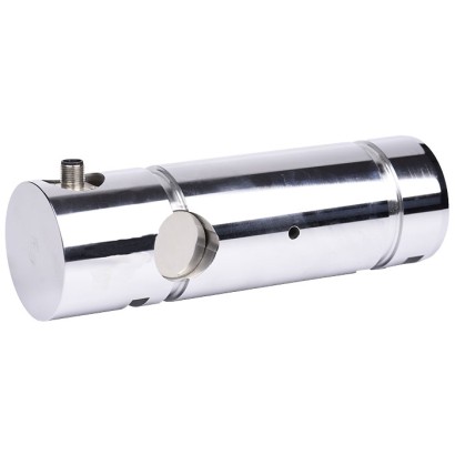
Load pin
Description
Load pins of the model F5802 are suitable for static and dynamic measuring tasks as a replacement for non-measuring bolts. They serve for determining tension and/or compression forces under harsh operating conditions.
The load pin is very often used in hoists and crane systems, e.g. used in construction cranes or in port and offshore cranes, as well as in the field of industrial weighing technology and special machine construction. There it is installed in particular in deflection pulleys, cable winches, fork or roller bearings.
Load pins of this model serve as reliable overload protection in mechanical and plant engineering.
The corresponding technical and regional approvals of these force transducers are, of course, available as options.
Load pin, model F5802
The load pin is made of high-strength, corrosion resistant 1.4542 stainless steel, the properties of which are ideal for the application areas.
As output signals, the common active current and voltage outputs are available (4 … 20 mA, 0 … 10 V). Redundant output signals and CANopen ® protocols are also
possible.
Special features
- Measuring ranges 20 ... 10,000 kN [204 tf ... 101,972 tf]
- Corrosion-resistant stainless steel version
- Existing non-measuring bolts are simply replaced by the load pins
- For overload protection in cranes and hoists
- Good reproducibility, easy installation
| Model | F5802 |
| Subcategory | Load pin |
| Force ranges | 20…10000 kN · 204…101972 tf |
| Accuracy class | 0.5 % ... 1 % Fnom |
| Process temperature | −10…+40 °C |
| Mounting type | Tension, compression |
| Output signal | 4 … 20 mA, 0 … 10 V, 1 ... 2 mV/V, CANopen® |
| Cell material | 1.4542 stainless steel, corrosion-resistant stainless steel |
| Ambient temperature | −20…+80 °C |
| IP rating | IP67 |
| Certifications | RoHSEACCE |
| Overload protection | 150 % |
| Datasheet languages | EN |
| Model | F5802 |
|---|---|
| Rated force F nom kN [tf] | 20 ... 10,000 [204 ... 101,972] |
| Relative linearity error d lin d lin 1) | 0.5 %...1%F nom |
| Relative Umkehrspanne v | 0.5 %...1%F nom |
| Relative repeatability error in unchanged mounting position b rg | 0.5 %...1%F nom |
| Temperature effect on | |
| characteristic valueTK C | 0.2 %Fnom /10 K |
| zero signal TK 0 | 0.2 %Fnom /10 K |
| Force limit F L | 150%F nom |
| Breaking force F B | 300%F nom |
| Material of measuring device | Corrosion-resistant stainless steel |
| Rated temperature B T, nom | -10 …+40 °C [14 ...+104 °F] |
| Operating temperature B T, G | -20 …+80 °C [-4 ...+176 °F] |
| Electrical connection | M12 x 1, 4-pin or 5-pin |
| Output signal (rated output) C nom | ■ 4 …20mA, 2-wire ■ 4 …20mA, 3-wire ■ 2 x 4 …20mA, redundant ■ DC 0 …10V, 3-wire ■ 2 x DC 0 …10Vredundant ■ 1 ... 2 mV/V ■ CANopen ® Protocol in accordance with CiA ® 301, device profile CiA ® 404, communication services LSS (CiA ® 305), configuration of the instrument address and baud rate Sync/Async, Node/ Lifeguarding, heartbeat; zero and span ±10 %adjustable via entries in the object directory 2) |
| Input resistance R e | 750 ± 30Ω |
| Output resistance R a | 700±5Ω |
| Isulation resistance R iS | ≥ 5,000MΩ |
| Supply voltage UB | ■ DC 9 ...36V for current output ■ DC 13 ...36V for voltage output ■ DC 5 ...10V for mV/V ■ DC 9 ...36V for CANopen ® |
| Ingress protection (acc. to IEC/EN 60529) | IP67 |
| Logo | Description | Region |
|---|---|---|
| EU declaration of conformity ■ EMCdirective ■ RoHS directive | European Union | |
| EAC EMCdirective | Eurasian Economic Community |
| Supply voltage + | Exc+ | Red |
|---|---|---|
| Supply voltage - | Exc- | Black |
| Signal + | Sig+ | Green |
| Signal - | Sig- | White |
| Shield | Shield | Yellow-green |
| Signal | Description |
|---|---|
| UB | Voltage source for sensor |
| UB+ | Sensor-supply voltage (+) |
| UB- | Sensor-supply voltage (-) |
| S+ | Output signal (+) |
| S- | Output signal (-) |
| 0 V | 0V potential |
View all (16)
| Signal | Description |
|---|---|
| A | Ammeter |
| V | Voltmeter |
| + - | Voltage source |
| Switch | |
| Shield (grounding) |
| Signal | 4 ... 20 mA, 2-wire | Cable colour |
|---|---|---|
| UB+/S+ | 1 | Brown |
| 0 V/S- | 3 | Black |
| Shield | Case / connector | - |
| Signal | 4 ... 20 mA, 3-wire | Cable colour |
|---|---|---|
| UB+ | 1 | Brown |
| S+ | 4 | Black |
| 0 V/S- | 3 | Blue |
| Shield | Case / connector | - |
| Signal | 0 ... 10 V, 3-wire | Cable colour |
|---|---|---|
| UB+ | 1 | Brown |
| S+ | 4 | Black |
| 0 V/S- | 3 | Blue |
| Shield | Case / connector | - |
| Signal | Description |
|---|---|
| UB | Voltage source for sensor |
| UB+ | Sensor-supply voltage (+) |
| UB- | Sensor-supply voltage (-) |
| UR | Voltage source for den signal jump |
| UR+ | Signal jump-supply voltage (+) |
| UR- | Signal jump-supply voltage (-) |
| S+ | Output signal (+) |
| S- | Output signal (-) |
| 0 V | 0V potential |
| Signal | Description |
|---|---|
| A | Ammeter |
| V | Voltmeter |
| + - | Voltage source |
| Switch | |
| Shield (grounding) |
| Signal | 4 ... 20 mA, 2-wire | Cable colour |
|---|---|---|
| UB+/S+ | 1 | Brown |
| 0 V/S- | 3 | Blue |
| UR+ | 2 | White |
| UR- | 4 | Black |
| Shield | Case / connector | - |
| Signal | 4 ... 20 mA, 3-wire | Cable colour |
|---|---|---|
| UB+ | 1 | Brown |
| 0 V/S- | 3 | Blue |
| UR+ | 2 | White |
| UR- | 3 | Blue |
| S+ | 4 | Black |
| Shield | Case / Connector | - |
| Signal | 0 ... 10 V, 3-wire | Cable colour |
|---|---|---|
| UB+ | 1 | Brown |
| 0 V/S- | 3 | Blue |
| UR+ | 2 | White |
| UR- | 3 | Blue |
| S+ | 4 | Black |
| Shield | Case / Connector | - |
| Signal | Description |
|---|---|
| CAN-SHLD, Shield | Shield |
| CAN-V+ | External positive voltage supply for the supply of the sensor |
| CAN-GND | External 0V Potential for the supply of the sensor |
| CAN-High | CAN_H Bus line (dominant high) |
| CAN-Low | CAN_L Bus line (dominant low) |
| Signal | Pin | Cable colour |
|---|---|---|
| CAN-SHLD, Shield | 1 / Case / connector | Brown |
| CAN-V+ | 2 | Blue |
| CAN-GND | 3 | White |
| CAN-High | 4 | Blue |
| CAN-Low | 5 | Black |
| Model | Description | Temperature range | Cable diameter | Cable colour | Order number |
|---|---|---|---|---|---|
| Straight version, cut to length, 4-pin, PUR cable, UL listed, IP67 | -20 ...+80 °C [-4 ...+176 °F] | 4.75 mm...5.7mm [0.18 in ... 0.22 in] | 2 m[6.6 ft] | 14259451 | |
| 5 m[16.4 ft] | 14259453 | ||||
| 10 m[32.8 ft] | 14259454 | ||||
| Straight version, cut to length, 5-pin, PUR cable, UL listed, IP67 | -20 ...+80 °C [-4 ...+176 °F] | 4.75 mm...5.7mm [0.18 in ... 0.22 in] | 2 m[6.6 ft] | 14259458 | |
| 5 m[16.4 ft] | 79100672 | ||||
| 10 m[32.8 ft] | 14259472 | ||||
| Angled version, cut to length, 4-pin, PUR cable, UL listed, IP67 | -20 ...+80 °C [-4 ...+176 °F] | 5.05 mm...6mm [0.2 in ... 0.24 in] | 2 m[6.6 ft] | 14259452 | |
| 5 m[16.4 ft] | 14293481 | ||||
| 10 m[32.8 ft] | 14259455 | ||||
| Angled version, cut to length, 5-pin, PUR cable, UL listed, IP67 | -20 ...+80 °C [-4 ...+176 °F] | 5.05 mm...6mm [0.2 in ... 0.24 in] | 2 m[6.6 ft] | 79101493 | |
| 5 m[16.4 ft] | 79100686 | ||||
| 10 m[32.8 ft] | On request |
Couldn't find the answer in the documentation? An engineer will reply within a business day.
Ask an engineer →