
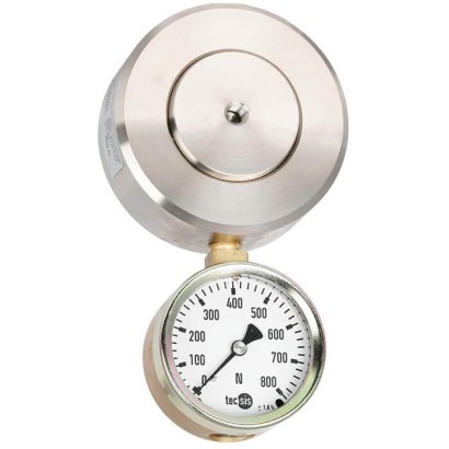
Hydraulic compression force transducer
Description
The compact hydraulic compression force transducer is available from a rated load of 320 N up to 120 kN. Hydraulic force measurement is a simple way to capture and display the forces occurring in various applications. Applications for hydraulic force measurement can be found in equipment manufacturing, in device and special machine building and also with measuring and control systems.
The force is measured using the principle of hydraulics: The force acting on a piston leads to a pressure increase that can be visualised on a connected display instrument. The scale of the display instrument can be defined in various units (e.g. N, kN, kg, t).
Hydraulic compression force transducer, model F1115
Special features
- Measuring ranges 0 ... 320 N to 0 ... 120 kN
- Relative linearity error ±1.0 ... 1.6 % F nom with analogue pressure gauge, ±0.5 % F nom with digital pressure gauge or pressure sensor (For rated loads below 500 N, the accuracy is ±1.6 % F nom for all connected measuring instruments.)
- Piston stroke ≤ 0.5 mm
- Operates without supply voltage
- 5-year leak-tightness warranty (Use of the force measuring unit as intended is a prerequisite for the extended 5-year warranty.)
| Model | F1115 |
| Subcategory | Hydraulic compression force transducer |
| Force ranges | 0…320 N · 0…120 kN · 320…120000 N |
| Accuracy class | ±1.6 % Fnom (analogue), ±0.5 % Fnom (digital) |
| Process temperature | −25…+50 °C |
| Mounting type | Direct mounting, Adapter, Capillary, Measuring hose |
| Cell material | Stainless steel |
| Ambient temperature | −25…+50 °C |
| IP rating | IP65 |
| Weight | 2.1 kg |
| Overload protection | 100 % |
| Datasheet languages | EN |
| Model F1115 | |
|---|---|
| Rated force F nom | 0 ... 320 N to 0 ... 120 kN |
| Nominal size | NS 20 |
| Display ■ Standard ■ Option | Pressure gauge 213.40 (NS 63) Digital pressure gauge DG-10 Pressure gauge 232.57 (NS 100), optionally with contacts Pressure sensor (on request) |
| Relative linearity error d lin ■ Standard ■ Option | ≤ ±1.6%F nom (analogue display) 1) ≤ ±0.5%F nom (pressure sensor/digital pressure gauge) 1) |
| Limit force F L | 100%F nom |
| Breaking force F B | > 130%F nom |
| Rated displacement s nom | < 0.5mm |
| Rated temperature range B T, nom | -25 …+50 °C |
| Ingress protection (per EN/IEC 60529) | IP65 |
| Case | Stainless steel |
| Piston | Stainless steel |
| Mounting type ■ Standard ■ Option | Direct mounting Adapter Capillary Measuring hose for 'separation without any losses' |
| Fill fluid | Glycerine/water 70 %/30% |
| Assembly aid | Threaded holes on the bottom of the case |
| Weight in kg ■ with pressure gauge 213.40 (NS 63) ■ with digital pressure gauge DG-10 | 2.1 2.3 |
| Version | Display | Options | ||||
|---|---|---|---|---|---|---|
| Rated force | System pressure | 213.40 | DG-10 | Measuring hose DN 2 [max. L 1) ] | Capillary [max. L 1) ] | |
| N/kN | bar | m | ||||
| 320 | N | 1.6 | | - | - | - |
| 500 | 2.5 | | - | - | - | |
| 800 | 4 | | - | - | 1.0 | |
| 1.2 | kN | 6 | | - | 0.5 | 1.0 |
| 2 | 10 | | - | 1.0 | 2.0 | |
| 3.2 | 16 | | - | 1.0 | 2.0 | |
| 4 | 20 | - | 2) | 1.5 | 2.0 | |
| 5 | 25 | | - | 1.5 | 2.0 | |
| 8 | 40 | | - | 1.5 | 2.0 | |
| 10 | 50 | - | | 2.0 | 2.0 | |
| 12 | 60 | | - | 2.0 | 2.0 | |
| 20 | 100 | | | 2.0 | 2.0 | |
| 32 | 160 | | | 2.0 | 4.0 | |
| 50 | 250 | | | 3.2 | 4.0 | |
| 60 | 315 | | - | 3.2 | 4.0 | |
| 80 | 400 | | | 3.2 | 6.0 | |
| 120 | 600 | | | 3.2 | 6.0 |
Couldn't find the answer in the documentation? An engineer will reply within a business day.
Ask an engineer →