
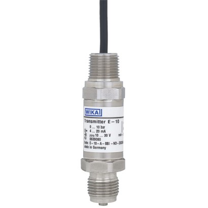
Pressure sensor with flameproof enclosure
Description
The model E-10 and E-11 pressure transmitters with flameproof enclosure have been designed specifically for the high demands of industrial oil and gas applications.
These pressure transmitters are available with various analogue signals, from 4 ... 20 mA to battery-powered, low-power versions, e.g DC 1 ... 5 V.
They feature an exceptionally high resistance to vibration, pressure spikes and moisture ingress.
On each individual instrument a comprehensive quality control and calibration is performed, so that an accuracy of ≤ 0.5 % can be ensured. Temperature compensation guarantees accuracy and long-term stability, even with strong
For further approvals, see page 6
Special features
- CSA- and FM-approved as “explosionproof” for class I, div. 1 hazardous areas
- ATEX- and IECEx-approved as “flameproof enclosure” for II 2G Ex db IIC T6...T1 Gb
- Current or voltage output
- Designed for harsh ambient conditions
- Low-power version available as an option
| Model | E-10 |
| Subcategory | Pressure transmitter |
| Pressure ranges | 0…0.6 bar · 0…1.6 bar · 0…2.5 bar · 0…4 bar · 0…6 bar · 0…10 bar · 0…16 bar · 0…1 bar · 0…0.4 bar · 0…25 bar · 0…40 bar · 0…60 bar · 0…100 bar · 0…160 bar · 0…250 bar · 0…400 bar · 0…600 bar · 0…1000 bar · -1…0 bar · -1…0.6 bar · -1…1.5 bar · -1…3 bar · -1…5 bar · -1…9 bar · -1…15 bar · -1…25 bar · 0…0.2 bar · 0…5 psi · 0…10 psi · 0…15 psi · 0…25 psi · 0…30 psi · 0…60 psi · 0…100 psi · 0…160 psi · 0…200 psi · 0…250 psi · 0…300 psi · 0…500 psi · 0…600 psi · 0…750 psi · 0…1000 psi · 0…1500 psi · 0…2000 psi · 0…3000 psi · 0…5000 psi · 0…8500 psi · 0…10000 psi · 0…15000 psi · -30…0 inHg · -30…30 inHg · -30…60 inHg · -30…100 inHg · -30…200 inHg · -30…300 inHg · 0…0 bar |
| Accuracy class | 0.5 % of span |
| Accuracy standard | IEC 61298-2 |
| Process connection | G ¼ BG ½ BG ¼ A⅛ NPT¼ NPT½ NPTG¼ female thread¼NPT female threadG½B flushG 1/4 BG 1/2 BG 1/4 A1/8 NPT1/4 NPT1/4 NPT female thread1/2 NPTG 1/2 B flush |
| Process temperature | −40…+105 °C |
| Output signal | 4 ... 20 mA · DC 0 ... 5 V · DC 0.5 ... 4.5 V · DC 1 ... 5 V · DC 0 ... 10 V · 0-5V · 0.5-4.5V · 1-5V · 0-10V |
| Power supply | DC 10...30 V |
| Electrical connection | ½ NPT male conduit, with potted cable outlet |
| Case material | Stainless steel |
| Wetted parts material | Stainless steel, Elgiloy® |
| Sealing material | NBR, FPM/FKM, EPDM |
| Ambient temperature | −40…+80 °C |
| IP rating | IP67 |
| Certifications | CERoHSNACEATEXIECExFMCSAEMC EN 61326Pressure Equipment Directive |
| Explosion protection | II 2G Ex db IIC T6...T1 Gb (ATEX)Ex db IIC T6...T1 Gb (IECEx)Explosionproof for Class I, division 1, groups A, B, C and D (FM)Explosionproof for Class I, division 1, groups A, B, C and D (CSA)Explosionproof for Class I, division 1, groups A, B, C and D; Class II, division 1, groups E, F and G; Class III, division 1; Type 4 (FM)Explosionproof for Class I, division 1, groups A, B, C and D; Class II, division 1, groups E, F and G; Class III, division 1; Type 4X (CSA)ATEX: II 2G Ex db IIC T6...T1 GbIECEx: Ex db IIC T6...T1 GbFM: Class I, Div. 1, Groups A,B,C,D; Class II, Div. 1, Groups E,F,G; Class III, Div. 1; Type 4CSA: Class I, Div. 1, Groups A,B,C,D; Class II, Div. 1, Groups E,F,G; Class III, Div. 1; Type 4X |
| Datasheet languages | EN |
| Non-linearity per BFSL per IEC 61298-2 | ≤ 0.2 %of span |
|---|---|
| Accuracy | →See'Max.measured error per IEC 61298-2' |
| Max. measured error per IEC 61298-2 | 0.5 %of span |
| Non-repeatability per IEC 61298-2 | ≤ 0.1 %of span |
| Mean temperature coefficient at 0 ... 80 °C [32 ... 176 °F] | |
| Zero point | ≤ 0.2 %of span/10 K |
| Span | ≤ 0.2 %of span/10 K |
| Long-term stability per DIN 16086 | ≤ 0.2 %of span/year |
| For use in hydrogen applications, observe the technical information IN 00.40 at www.wika. com regarding long-term stability. | |
| Reference conditions | Per IEC 61298-1 |
| bar | |
|---|---|
| Scale range | Overpressure limit |
| 0 ... 0.4 | 3.1 |
| 0 ... 0.6 | |
| 0 ... 1 | |
| 0 ... 1.6 | 6.2 |
| 0 ... 2.5 | |
| 0 ... 4 | 14 |
| 0 ... 6 | 31 |
| 0 ... 10 | |
| 0 ... 16 | 62 |
| 0 ... 25 | |
| 0 ... 40 | 80 |
| 0 ... 60 | 120 |
| 0 ... 100 | 200 |
| 0 ... 160 | 320 |
| 0 ... 250 | 500 |
| 0 ... 400 | 800 |
| 0 ... 600 1) 3) | 1,200 |
| 0 ... 1000 2) 3) | 1,500 |
| psi | |
|---|---|
| Scale range | Overpressure limit |
| 0 ... 5 | 45 |
| 0 ... 10 | |
| 0 ... 15 | |
| 0 ... 25 | 89 |
| 0 ... 30 | |
| 0 ... 60 | 203 |
| 0 ... 100 | 449 |
| 0 ... 160 | 899 |
| 0 ... 200 | |
| 0 ... 250 | |
| 0 ... 300 | |
| 0 ... 500 | 1,160 |
| 0 ... 600 | |
| 0 ... 750 | 1,740 |
| 0 ... 1,000 | |
| 0 ... 1,500 | 2,900 |
| 0 ... 2,000 | 4,600 |
| 0 ... 3,000 | 7,200 |
| 0 ... 5,000 | 11,600 |
| 0 ... 8,500 1) 3) | 17,400 |
| 0 ... 10,000 2) 3) | |
| 0 ... 15,000 2) 3) | 21,750 |
| bar | |
|---|---|
| Scale range | Overpressure limit |
| 0 ... 0, | 2 |
| 0 ... 0.6 | 4 |
| 0 ... 1 | 5 |
| 0 ... 1.6 | 10 |
| 0 ... 2.5 | |
| 0 ... 4 | 17 |
| 0 ... 6 | 35 |
| 0 ... 10 | |
| 0 ... 16 | 50 |
View all (20)
| bar | |
|---|---|
| Scale range | Overpressure limit |
| -1 ... 0 | 2 |
| -1 ... +0.6 | 4 |
| -1 ... +1.5 | 5 |
| -1 ...+3 | 10 |
| -1 ...+5 | 17 |
| -1 ...+9 | 35 |
| -1 ...+15 | |
| -1 ...+25 | 50 |
| psi | |
|---|---|
| Scale range | Overpressure limit |
| 0 ... 15 | 72 |
| 0 ... 25 | 145 |
| 0 ... 30 | |
| 0 ... 60 | 240 |
| 0 ... 100 | 500 |
| psi | |
|---|---|
| Scale range | Overpressure limit |
| -30 inHg ... 0 | 29 |
| -30 inHg ... 30 | 145 |
| 500-30 inHg ... 60 | 240 |
| -30 inHg ... 100 | 500 |
| -30 inHg ... 200 | 1,160 |
| -30 inHg ... 300 |
| Units | ■ bar ■ psi ■ kg/cm² ■ MPa, kPa |
|---|---|
| Maximum working pressure | → Corresponds to the upper measuring range value / measuring range full scale value |
| Overpressure limit | →See measuring ranges The overpressure limit is based on the measuring range. Depending on the selected pro- cess connection and the seal, restrictions in overpressure limit can result. |
| Vacuum resistance | Yes |
| Standard | Thread size | Max. measuring range | Overpressure limit | Seal |
|---|---|---|---|---|
| Process connections for model E-10 | ||||
| EN 837 | G¼B | 1,000 bar [15,000 psi] | 1,480 bar [21,400 psi] | - |
| G¼female thread | 1,000 bar [15,000 psi] | 1,480 bar [21,400 psi] | - | |
| G½B | 1,000 bar [15,000 psi] | 1,480 bar [21,400 psi] | - | |
| DIN EN ISO 1179-2 (formerly DIN 3852-E) | G¼A | 600 bar [8,700 psi] | 858 bar [12,440 psi] | NBR |
| ANSI/ASME B1.20.1 | ⅛NPT | 400 bar [5,800 psi] | 572 bar [8,290 psi] | - |
| ¼NPT | 1,000 bar [15,000 psi] | 1,480 bar [21,400 psi] | - | |
| ¼NPTfemale thread | 1,000 bar [15,000 psi] | 1,480 bar [21,400 psi] | - | |
| ½NPT | 1,000 bar [15,000 psi] | 1,480 bar [21,400 psi] | - | |
| Process connections for model E-11 | ||||
| - | G½Bflush (available for measuring ranges 0 ... 2.5 to 0 ... 600 bar) | 600 bar [8,700 psi] | 600 bar [8,700 psi] | NBR |
| 400 bar [5,800 psi] | 400 bar [5,800 psi] | FPM/FKM | ||
| 200 bar [2,900 psi] | 200 bar [2,900 psi] | EPDM | ||
| - | G½Bflush (available for measuring ranges 0 ... 4 to 0 ... 1,6 bar) | 1.6 bar [20 psi] | 10 bar [145 psi] | NBR |
| 1.6 bar [20 psi] | 10 bar [145 psi] | FPM/FKM | ||
| 1.6 bar [20 psi] | 10 bar [145 psi] | EPDM |
| Possible restrictions | Depending on the choice of seal on the process connection, there may be restrictions in the permissible medium and ambient temperature range. |
|---|---|
| NBR | -30 ...+100 °C [-22 ...+212 °F] |
| FPM/FKM | -15 ...+102 °C [5 ... 215 °F] / -15 ...+105 °C [5 ... 221 °F] |
| Signal type | |
|---|---|
| Current (2-wire) | 4 ...20mA |
| Voltage (3-wire) | ■ DC 0 ...5V ■ DC 0.5 ...4.5V ■ DC 1 ...5V ■ DC 0 ...10V |
| Load in Ω | |
| Output signal 4 ...20mA | ≤ (auxiliary power - 10 V) / 0.02 A |
| Output signal DC 0 ...5V | > maximum output signal /1mA |
| Output signal DC 0.5 ...4.5V | > 100k |
| Output signal DC 1 ...5V | > 100k |
| Output signal | |||
|---|---|---|---|
| Output signal DC 0 ...10V | > maximum output signal /1mA | ||
| Voltage supply | |||
| Auxiliary power | Output signal 4 ...20mA | DC 10 ...30V | |
| Output signal DC 0 ...5V | DC 10 ...30V | ||
| Output signal DC 0.5 ...4.5V | DC 5 ...30V | ||
| Output signal DC 1 ...5V | DC 6 ...30V | ||
| Output signal DC 0 ...10V | DC 14 ...30V | ||
| Power consumption | 1W | ||
| Dynamic behaviour | |||
| Settling time per IEC 61298-2 | ≤ 2 ms | ||
| ≤ 10 ms | For model E-10 with measuring range ≤ 0 ... 25 bar at medium temperature -30 °C [-22 °F] | ||
| For model E-11 |
| Connection type | IP code 1) 2) | Wire cross-sec- tion in mm² | Cable diameter in mm[in] | Cable lengths | Cable material |
|---|---|---|---|---|---|
| ½ NPT male conduit, with pot- ted cable outlet (ATEX and IECEx approval) | IP67 | 3 x 0.5 AWG20 | 6.8 [0.27] | ■ 2m ■ 5m ■ 10m | Polyolefin copolymer |
| ½ NPT male conduit, with cable outlet (FM and CSA approval) | NEMA 4x IP67 | 3 x 0.56 AWG20 | 5.4 [0.21] | ■ 6 ft ■ 10m ■ 20 ft ■ 30 ft | PVC |
| ½ NPT male conduit, with pot- ted cores (FM and CSA approval) | NEMA 4x IP67 | 3 x 0.5 AWG20 | 3 x 2.6 [3 x 0.10] | ■ 6 ft ■ 10m ■ 20 ft ■ 30 ft | Polyolefin |
| Short-circuit resistance | S+ vs. U- |
|---|---|
| Reverse polarity protection | U+ vs. U- |
| Insulation voltage | DC 500V |
| Permissible temperature ranges 1) 2) 3) 4) | |||
|---|---|---|---|
| Instruments per ATEX and IECEx | Medium and ambient tem- perature limit | T6 | -40 ...+60 °C [-40 ...+140 °F] |
| T5 | -40 ...+75 °C [-40 ...+167 °F] | ||
| T4 ...T1 | -40 ...+105 °C [-40 ...+221 °F] | ||
| Storage temperature limit | -40 ...+70 °C [-40 ...+158 °F] | ||
| Instruments per FM, CSA | Medium and ambient tem- perature limit | T6 | -40 ...+60 °C [-40 ...+140 °F] |
| T4 ...T1 | -40 ...+105 °C [-40 ...+221 °F] | ||
| Storage temperature limit | -40 ...+70 °C [-40 ...+158 °F] | ||
| Vibration resistance per IEC 60068-2-6 | 10g | ||
| Shock resistance per IEC 60068-2-27 | 100g (mechanical shock) | ||
| Ingress protection (IP code) per IEC 60529 4) | → See 'Electrical connection' |
| Oil- and grease-free | ||
|---|---|---|
| Residual hydrocarbon | < 1,000 mg/m² | |
| Packaging | Protective cap on the process connection | |
| Oxygen, oil- and grease-free | ||
| Measuring ranges | Max. 400 bar [5,000 psi] | |
| Overpressure limit | 2 times | |
| Residual hydrocarbon | Measuring ranges < 30 bar [435 psi] | < 500 mg/m 2 |
| Measuring ranges > 30 bar [435 psi] | < 200 mg/m 2 | |
| Packaging | Protective cap on the process connection | |
| Max. permissible temperature range | -20 ...+60 °C [-4 ...+140 °F] | |
| Elastomer seal | Max. -15 ...+60 °C [5 ... 140 °F] and max. 30 bar [435 psi] measuring | |
| → Not possible with process connections with female thread | ||
| Hydrogen | On request |
| Packaging | Individual packaging |
|---|---|
| Instrument labelling | WIKA product label, glued |
| Logo | Description | Country |
|---|---|---|
| EU declaration of conformity | European Union | |
| EMCdirective EN 61326 emission (group 1, class B) and immunity (industrial environments) | ||
| Pressure Equipment Directive | ||
| RoHS directive | ||
| ATEX directive Flameproof enclosure (Ex d), EN 60079-0, EN 60079-1 | ||
| IECEx Hazardous areas Flameproof enclosure (Ex d), IEC 60079-0, IEC 60079-1 | International | |
| FM Hazardous areas Explosionproof class 3600, class 3615, class 3810 | USA | |
| CSA ■ Safety (e.g. electr. safety, overpressure, ...) ■ Hazardous areas Class 2258 02, class 2258 82 | USA and Canada |
| Logo | Description | Country |
|---|---|---|
| KCs Hazardous areas | Korea | |
| - | CRN Safety (e.g. electr. safety, overpressure, ...) | Canada |
| Logo | Description |
|---|---|
| - | China RoHS directive |
Couldn't find the answer in the documentation? An engineer will reply within a business day.
Ask an engineer →1 standard articles of family E-10
If you know the code — pick directly. If not — use the configurator in mode “01”.