
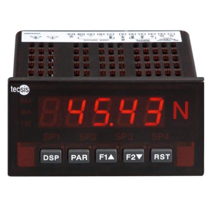
Industrial mV/V measuring instruments
Description
mV/V measuring instruments as a display for the panel mounting or as a large display E1930 are well suited for numerous applications because of their accuracy and being easy to read. Measured values and the status of the relay outputs are shown on the 5-digit digital multi-function display. The measuring instruments also offer a totalizer as well as Min/Max memory.
The connection to the corresponding force transducer and the parameterisation are usually performed by the customer for this model. Programming the instrument is menu-driven. Any strain gauge force transducer (a maximum of 4 sensors of 350 Ω in parallel) with an output signal of up to max. ±4.8 mV/V or ±48 mV/V can be connected. The internal sensor supply is either DC 5 or 10 V.
Industrial mV/V measuring instruments, large display or display model E1930
Requests and parameterisation of different values are possible by way of the optional serial interface. The optional 2 or 4 relays allow the monitoring of falling below or exceeding limit values. In addition, a 0/4 ... 20 mA output signal is available for analogue evaluation. Disruptive signals can be eliminated by filter setting options.
Special features
- 5-digit digital display, easy to read up to 50 m
- High accuracy: 0.02 % of reading +3 μV
- Extensive functions easy to set on the instrument or via PC
- Plug-in expansion cards, analogue output, 2 or 4 limit values, serial interface
- Ingress protection IP65
| Model | E1930 |
| Subcategory | Measuring instrument with display |
| Accuracy class | ±0.02 % of FS ± 1 digit |
| Process temperature | +0…+45 °C |
| Output signal | 0 ... 20 mA, DC 0 ... 10 V |
| Ambient temperature | +0…+50 °C |
| IP rating | IP65/IP20 |
| Weight | 2.25 kg |
| Certifications | UL |
| Datasheet languages | EN |
| Model E1930 | |
|---|---|
| Measuring range | Full-bridge strain gauge in 4-wire technology Option: 6-wire technology connection available Selectable by jumper: ■ ±24mV ■ ±240mV |
| Display | 5-digit, red, LED display readable in sunlight, 14 or 100 mmhigh Output max. -19,999 to +99,999 digits Refresh rate: 1 to 20 updates/s. Min./Max. display Relay status display |
| Sensor supply | Selectable by jumper: DC 5V ±2 %, max.65mA DC 10V ±2 %, max.125mA |
| Accuracy | ±0.02 %of FS ± 1 digit |
| Linearisation | Number of linearisation steps: Selectable from 2 to 16 Scale range: -19,999 to 99,999 Decimal point: 0 to 0.0000 |
| Rated temperature range | 18…28°C |
| Service temperature B T, G | 0 …50°C(with all 3 cards inserted 0 …45°C) |
| Storage temperature range | -40…60°C |
| Output signal (option) | 2 or 4 relay outputs (transistor outputs available as an alternative) Analogue output 0 ... 20 mAand DC 0 ...10V RS-232 interface RS-485 interface Profi-DP interface |
| Digital input | 3 programmable user inputs Maximum voltage:DC 30V Maximum step response time: 50 ms Selectable by jumper: ■ NPN:Active Vin < DC 0.9 V, inactive Vin > DC 3.6V ■ PNP: Active Vin > DC 3.6 V, inactive Vin < DC 0.9V |
| Resolution | 16-bit A/D converter |
| Sampling rate | 20 Hz |
| Supply voltage ■ Standard ■ Option | AC 85 …250V, 50/60 Hz, 15VA DC 11 …36V, 11W/ AC 24 V, 15VA |
| Response time | < 200 ms for displaying 99 %of the final reading value without zero adjustment < 700 ms for displaying 99 %of the final reading value with zero adjustment The response time changes with setting digital stage filtering |
| Ingress protection (per IEC/EN 60529) | IP65 (front only) IP20 (rear of unit) |
| Interference emission | CISPR 11 class A |
| Immunity | EN 61326-1 immunity for industrial areas |
| Common-mode rejection (CMR) | > 100 dB, DC to 120 Hz |
| Relative humidity | max. 85 %r.h., non-condensing |
| Approvals | UL approval (Underwriters Laboratories) for the USA and Canada |
| Weight | Display: approx. 300g (without plug-in options) Large display: approx. 2.25 kg (including measurement module) |
| Pin | Connections | |
|---|---|---|
| 1 | AC | AC 85 - 250V 50/60 Hz |
| 2 | AC | AC 85 - 250V 50/60 Hz |
| 3 | +SIG | Signal input + |
| 4 | -SIG | Signal input - |
| 5 | COMM. | Ground signal input |
| 6 | +EXCITATION | Bridge supply |
| 7 | USERCOMM | Ground user input |
| 8 | USER1 | User input 1 |
| 9 | USER2 | User input 2 |
| 10 | USER3 | User input 3 |
Couldn't find the answer in the documentation? An engineer will reply within a business day.
Ask an engineer →