
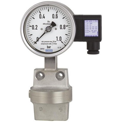
Differential pressure gauge with output signal
Description
Wherever the process pressure has to be indicated locally and, at the same time, a signal transmission to the central control or remote centre is desired, the model DPGT43 intelliGAUGE ® (patent, property right: e.g. DE 202007019025) can be used.
These differential pressure gauges are made of highly corrosion-resistant stainless steel and feature an all-metal sealing of the media chamber.
Therefore no elastomer sealing elements are required, so that a better long-term leak tightness is ensured. A high overload safety is achieved by the all-metal construction and the close-fitting design of the pressure element.
The robust diaphragm measuring system produces a pointer rotation proportional to the pressure. An electronic angle encoder, proven in safety-critical automotive applications, determines the position of the pointer shaft - it is a non-contact sensor and therefore completely free from wear and friction.
Special features
- No configuration necessary due to “plug-and-play”
- Signal transmission per NAMUR
- Differential pressure measuring ranges from 0 … 16 mbar or 0 ... 10 inH 2 O
- Individual, non-linear characteristic curves (e. g. x 2 or √x for flow measurement)
- QR code on dial links to instrument-specific information
| Model | DPGT43.100 |
| Product family | DPGT43 |
| Subcategory | Differential pressure gauge with output signal |
| Pressure ranges | 0…16 mbar · 0…10 inH2O · 0…0.25 bar · 0…6 psi · 0…40 kPa · 0…160 mbar · 0…2500 mbar · 0…1.6 bar · 0…40 bar · 0…1.6 kPa · 0…2500 kPa · 0…150 inH2O · 0…600 psi · 0…25 mbar · 0…40 mbar · 0…60 mbar · 0…100 mbar · 0…250 mbar · 0…300 mbar · 0…400 mbar · 0…600 mbar · 0…1000 mbar · 0…1100 mbar · 0…1200 mbar · 0…1600 mbar · 0…0.4 bar · 0…0.6 bar · 0…1 bar · 0…2.5 bar · 0…4 bar · 0…6 bar · 0…7 bar · 0…10 bar · 0…14 bar · 0…16 bar · 0…20 bar · 0…25 bar · 0…30 bar · 0…2.5 kPa · 0…4 kPa · 0…6 kPa · 0…10 kPa · 0…16 kPa · 0…25 kPa · 0…30 kPa · 0…100 kPa · 0…160 kPa · 0…250 kPa · 0…300 kPa · 0…400 kPa · 0…600 kPa · 0…700 kPa · 0…800 kPa · 0…1000 kPa · 0…1400 kPa · 0…1600 kPa · 0…15 inH2O · 0…20 inH2O · 0…25 inH2O · 0…30 inH2O · 0…40 inH2O · 0…60 inH2O · 0…100 inH2O · 0…200 inH2O · 0…250 inH2O · 0…8 psi · 0…10 psi · 0…15 psi · 0…30 psi · 0…60 psi · 0…100 psi · 0…150 psi · 0…160 psi · 0…200 psi · 0…250 psi · 0…300 psi · 0…400 psi |
| Accuracy class | 1.6 |
| Accuracy standard | EN 837-3 |
| Process connection | G ¼, female threadG ½ B, male thread¼ NPT, female thread½ NPT, male threadG¼G½½NPTG1/4G1/2B1/4NPT1/2NPT |
| Process temperature | −20…+150 °C |
| Output signal | 4-20mA · 0-20mA · 0-10V |
| Power supply | 12...30 V DC |
| Electrical connection | Cable socket PA 6, black; M20 x 1.5 cable gland; 6 screw terminals + PE |
| Case material | Stainless steel 1.4301 (304 SS), Stainless steel 1.4571 (316 Ti) |
| Wetted parts material | Stainless steel 1.4571 (316 Ti), NiCr alloy (Inconel) |
| Sealing material | All-metal sealing, Stainless steel |
| Ambient temperature | −40…+60 °C |
| IP rating | IP65 |
| Weight | 2.7 kg |
| Certifications | CERoHSEACCRN |
| Explosion protection | Ex UkraineNEPSIII 2G Ex ia IIC T6/T5/T4 GbII 2D Ex ia IIIB T135°C DbEx ia IIC T6/T5/T4 GbEx ia IIIB T135°C DbIECEx Hazardous areas Gas Ex ia IIC T6/T5/T4 GbGas II 2G Ex ia IIC T6/T5/T4 GbDust II 2D Ex ia IIIB T135℃ DbGas Ex ia IIC T6/T5/T4 GbDust Ex ia IIIB T135℃ DbEACPAC KazakhstanMChSPAC UzbekistanCRN |
| Dial size | 100 mm |
| Datasheet languages | EN, DE |
| Zero point setting | |
|---|---|
| Instruments with case filling | Without |
| Instruments without case filling | ■ Without ■ Setting by means of adjustable pointer |
| Influence of static pressure 1) | |
| Span ≤ 0.25 bar [100 inH 2 O] | ±0.3 %/1 bar [14.5 psi] |
| Span ≥ 0.4 bar [160 inH 2 O] | ±0.04 %/1 bar [14.5 psi] |
| Accuracy of output signal | |
| Accuracy | ±1 %of measuring span |
| Linearity error | ≤ 1 %of measuring span (terminal method) 2) |
| Influence of auxiliary power | < 0.1 %of FS/10V |
| Influence of load | ≤ 0.1 %of FS |
| Long-term stability | < 0.3 %of FS/a |
| Resolution | 0.13 %of full scale (10 bit resolution at 360°) |
| Measuring rate | 100 per minute |
| Temperature error | On deviation from the reference conditions at the measuring system: ≤ ±0.5 %per 10 °C [≤ ±0.5 %per 18 °F] of full scale value |
| Reference conditions | |
| Ambient temperature | +20 °C [+68 °F] |
| mbar | ||
|---|---|---|
| 0 ... 16 1) 0 ... 25 | 0 ... 160 0 ... 250 | 0 ... 1,000 0 ... 1,100 |
| 0 ... 300 | 0 ... 1,200 | |
| 0 ... 40 | 0 ... 1,600 | |
| 0 ... 60 | 0 ... 400 | |
| 0 ... 100 | 0 ... 600 | 0 ... 2,500 |
| bar | 0 ... 4 | |
|---|---|---|
| 0 ... 0.25 0 ... 0.4 | 0 ... 6 | 0 ... 20 0 ... 25 |
| 0 ... 0.6 | 0 ... 7 | 0 ... 30 |
| 0 ... 1 | 0 ... 10 | 0 ... 40 |
| 0 ... 1.6 | 0 ... 14 | - |
| 0 ... 2.5 | 0 ... 16 | - |
| kPa | ||
|---|---|---|
| 0 ... 1.6 1) 0 ... 2.5 | 0 ... 40 0 ... 60 | 0 ... 700 0 ... 800 |
| 0 ... 4 | 0 ... 100 | 0 ... 1,000 |
| 0 ... 6 | 0 ... 160 | 0 ... 1,400 |
| 0 ... 10 | 0 ... 250 | 0 ... 1,600 |
| 0 ... 16 | 0 ... 300 | 0 ... 2,500 |
| 0 ... 25 | 0 ... 400 | - |
| 0 ... 30 | 0 ... 600 | - |
View all (20)
| 0 ... 6 | 0 ... 60 | 0 ... 250 |
|---|---|---|
| 0 ... 8 | 0 ... 100 | 0 ... 300 |
| 0 ... 10 | 0 ... 150 | 0 ... 400 |
| 0 ... 15 | 0 ... 160 | 0 ... 600 |
| 0 ... 30 | 0 ... 200 | - |
| mbar | ||
|---|---|---|
| -16 ... 0 1) | -600 ... 0 | -50 ...+50 |
| -25 ... 0 | -1,000 ... 0 | -80 ...+80 |
| -40 ... 0 | -1,100 ... 0 | -125 ...+125 |
| -60 ... 0 | -1,200 ... 0 | -200 ...+200 |
| -100 ... 0 | -8 ...+8 | -300 ...+300 |
| -160 ... 0 | -10 ...+15 | -500 ...+500 |
| -250 ... 0 | -20 ...+20 | -600 ...+400 |
| -400 ... 0 | -30 ...+30 | -1,000 ...+600 |
| bar | ||
|---|---|---|
| -1 ... 0 | -1 ...+3 | -1 ...+15 |
| -1 ... +0.6 | -1 ...+5 | -1 ...+24 |
| -15 ... 0 inHg | -30 inHg ...+300 |
|---|---|
| -30 ... 0 inHg | -5 ...+5 |
| -30 inHg ...+15 | -15 ...+15 |
| -30 inHg ...+30 | -30 ...+30 |
| -30 inHg ...+60 | -50 ...+50 |
| -30 inHg ...+100 | -100 ...+100 |
| -30 inHg ...+160 | -150 ...+150 |
| -30 inHg ...+200 | - |
| kPa | ||
|---|---|---|
| -60 ... 0 -100 ... 0 | -15 ...+15 -20 ...+40 | -100 ...+500 -100 ...+700 |
| -2 ...+4 | -100 ...+60 | -100 ...+900 |
| -4 ...+6 | -100 ...+100 | -100 ... +1,000 |
| -6 ...+4 | -100 ...+150 | -100 ... +1,500 |
| -6 ...+10 | -100 ...+200 | -100 ... +2,400 |
| -10 ...+6 | -100 ...+300 | - |
| -10 ...+15 | -100 ...+400 | - |
| Unit | ■ mbar ■ bar ■ psi ■ kPa ■ MPa ■ mmH 2 O ■ inH 2 O | |
|---|---|---|
| → Other units on request | ||
| Overload safety and max. operating pressure (static pressure) | The possibility of selection depends on the scale range. → See separate table | |
| Dial | ||
| Scale layout | ■ Single scale ■ Dual scale | |
| Scale colour | Single scale | Black |
| Dual scale | Black/red | |
| Material | Aluminium | |
| Customer-specific version | ■ Without ■ With special scale, e.g. linear pressure or square root incrementation | |
| Other scales, e.g. with red mark, circular arcs or circular sectors, on request → Alternatively, adhesive label set for red and green circular arcs; see data sheet AC 08.03 | ||
| Pointer | ||
| Instrument pointer | With case filling | Standard pointer, aluminium, black |
| Without case filling | Adjustable pointer, aluminium, black | |
| Mark pointer/drag pointer | ■ Without Mark pointer on bayonet ring, adjustable | |
| Pointer stop pin | ■ Without At 6 o'clock |
| Span 1) | Overload safety / max. operating pressure (static) Either side max. |
|---|---|
| 16 ... 40 mbar [10 ... 16 inH 2 O] | ■ 2.5 bar [36 psi] / 2.5 bar [36 psi] ■ 2.5 bar [36 psi] / 6 bar [87 psi] 2) |
| 60 ... 250 mbar [25 ... 100 inH 2 O] | ■ 2.5 bar [36 psi] / 6 bar [87 psi] ■ 6 bar [87 psi] / 10 bar [145 psi] 2) |
| 400 mbar [6 psi] | ■ 4 bar [58 psi] / 25 bar [363 psi] ■ 40 bar [600 psi] / 40 bar [600 psi] 2) |
| 0.6 bar [10 psi] | ■ 6 bar [87 psi] / 25 bar [363 psi] ■ 40 bar [600 psi] / 40 bar [600 psi] 2) |
| 1 bar [15 psi] | ■ 10 bar [145 psi] / 25 bar [363 psi] ■ 40 bar [600 psi] / 40 bar [600 psi] 2) |
| 1.6 bar [30 psi] | ■ 16 bar [232 psi] / 25 bar [363 psi] ■ 40 bar [600 psi] / 40 bar [600 psi] 2) |
| 2.5 ... 40 bar [60 ... 600 psi] | ■ 25 bar [363 psi] / 25 bar [363 psi] ■ 40 bar [600 psi] / 40 bar [600 psi] 2) |
| Standard | ■ EN 837-3 ■ ANSI/B1.20.1 | |
|---|---|---|
| → For valve manifolds for an instrument hook-up, see 'Accessories and spare parts'. | ||
| Size | ||
| EN 837-3 | ■ 2 x G¼, female thread ■ 2 x G½B,male thread | |
| ANSI/B1.20.1 | ■ 2 x ¼NPT, female thread ■ 2 x ½NPT, male thread | |
| Restrictor | ■ Without ■ ∅0.6 mm[0.024"], stainless steel ■ ∅0.3 mm[0.012"], stainless steel | |
| Material (wetted) | ||
| Media chambers with process connection | Stainless steel 1.4571 (316 Ti) | |
| Venting of the media chambers | Stainless steel 1.4571 (316 Ti) | |
| Diaphragm element 1) | Span ≤ 0.25 bar [100 inH 2 O] | Stainless steel 1.4571 (316 Ti) |
| Span ≥ 0.4 bar [160 inH 2 O] | NiCr alloy (Inconel) | |
| Bellows | Stainless steel 1.4571 (316 Ti) |
| Signal type | ■ Variant 1: 4 …20mA, 2-wire, passive, per NAMUR NE 43 ■ Variant 2: 4 ... 20 mA, 2-wire, for hazardous areas ■ Variant 3: 0 ... 20 mA, 3-wire ■ Variant 4: 0 ... 10 V, 3-wire | |
|---|---|---|
| Auxiliary power | ||
| Supply voltage | Variant 1, 3 | U B = DC >12 ...≤ 30V |
| Variant 2 | U B = DC >14 ...≤ 30V | |
| Variant 4 | U B = DC >15 ...≤ 30V | |
| Permissible residual ripple of supply voltage | < 10 %ss | |
| Load | Variant 1, 2, 3 | R A ≤ (Supply voltage - 12 V)/0.02 A, max.600Ω |
| Variant 4 | R A = 100 kΩ |
| Operating conditions | |
|---|---|
| Medium temperature range | ■ -20 ...+100 °C [-4 ...+212 °F] ■ -20 ...+120 °C [-4 ...+248 °F] ■ -20 ...+150 °C [-4 ...+284 °F] |
| Ambient temperature range | ■ -20 ...+60 °C [-4 ...+140 °F] ■ -40 ...+60 °C [-40 ...+140 °F] 1) |
| Storage temperature range | -20 ...+60 °C [-4 ... 140 °F] |
| Pressure limitation | |
| Steady | Full scale value |
| Fluctuating | 0.9 x full scale value |
| Ingress protection per IEC/EN 60529 2) | ■ IP54 ■ IP65 ■ IP66 |
| Description | Region |
|---|---|
| EU declaration of conformity | European Union |
| EMCDirective | |
| LowVoltage Directive | |
| RoHS directive |
| Logo | Description | Region |
|---|---|---|
| EU declaration of conformity | European Union | |
| IECEx 1) Hazardous areas Gas Ex ia IIC T6/T5/T4 Gb | International | |
| EAC EMCDirective LowVoltage Directive | Eurasian Economic Community | |
| Ex Ukraine Hazardous areas | Ukraine | |
| NEPSI Hazardous areas | China | |
| PAC Kazakhstan Metrology, measurement technology | Kazakhstan | |
| Permission for commissioning PAC Uzbekistan | Uzbekistan | |
| Metrology, measurement technology | ||
| - | CRN Safety (e.g. electr. safety, overpressure, ...) | Canada |
| Certificates | ■ 2.2 test report per EN 10204 (e.g. state-of-the-art manufacturing, indication accuracy) ■ 3.1 inspection certificate per EN 10204 (e.g. indication accuracy) |
|---|---|
| Recommended calibration interval | 1 year (dependent on conditions of use) |
| Patent number | Description |
|---|---|
| DE 202007019025, US 2010045366, CN 101438333 | Pointer measuring instrument with output signal 4 ...20mA |
| US Design D1051747S, CPC CN 01677074, DE Design 402022100171, EU Design 402022100171, IR Design DM/222416, EU 3D trademark 018659564 | WIKA blue identity design patent |
| Connection values | |
|---|---|
| Max. voltage U i | DC 30V |
| Max. current I i | 100mA |
| Max. power P i | 720mW |
| Effective internal capacitance C i | 11 nF |
| Effective internal inductance L i | Negligible |
| NS | Span 1) | Dimensions inmm | Weight in | |||||||||
|---|---|---|---|---|---|---|---|---|---|---|---|---|
| a | b | c | d | D 1 | D 2 | e | G | h ±1 | H | kg | ||
| 100 [4"] | ≤ 0.25 bar [100 inH 2 O] | 25 | 59.5 | 94 | 140 | 101 | 99 | 17 | G¼ | 161 | 90 | 2.7 |
| 100 [4"] | ≥ 0.4 bar [160 inH 2 O] | 25 | 59.5 | 94 | 78 | 101 | 99 | 17 | G¼ | 171 | 87 | 1.9 |
| 160 [6"] | ≤ 0.25 bar [100 inH 2 O] | 25 | 65 | 124 | 140 | 161 | 159 | 17 | G¼ | 191 | 120 | 3.4 |
| 160 [6"] | ≥ 0.4 bar [160 inH 2 O] | 25 | 65 | 124 | 78 | 161 | 159 | 17 | G¼ | 201 | 117 | 2.4 |
Couldn't find the answer in the documentation? An engineer will reply within a business day.
Ask an engineer →