
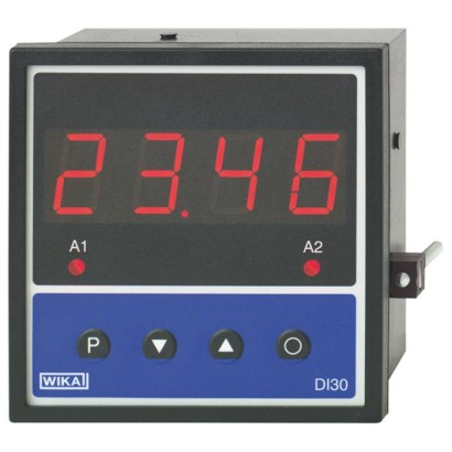
Digital indicator for panel mounting
Description
The DI30 digital indicator has been developed specifically for the display of measured values from electronic transmitters, such as pressure transmitters and temperature transmitters. It offers various input configurations for 0/4 ... 20 mA, DC 0 ... 5 V and DC 0 ... 10 V standard signals, which can be selected through the terminal configuration and input selection within the instrument configuration.
Thus, as an alternative, transmitters with current or voltage signals can be connected on the same instrument.
Using the transmitter power supply, current loop sensors (2-wire) as well as 3-wire and 4-wire sensors can be operated. The transmitter power supply is galvanically-isolated from the measuring input.
Two alarm outputs are available.
Digital indicator model DI30
In addition, the indicator offers the possibility for sensor calibration and linearisation of up to 10 points. This makes further adaptation to different sensor signals and application requirements possible.
The standard features are completed with the adjustable sampling and display rates, and the input offset, for correcting zero offsets and sensor drift. Similarly, functions such as HOLD and TARE are included. Unauthorised alteration of the set instrument parameters can be prevented via different user levels, in conjunction with a freelyselectable access code.
All configuration and programming can be carried out through the front-panel keys
Special features
- Freely-selectable input: 4 ... 20 mA, 0 ... 20 mA, DC 0 ... 5 V, DC 0 ... 10 V
- Transmitter power supply DC 24 V
- Minimum and maximum value memory
- 2 freely-programmable alarm outputs
- Linearisation with up to 10 programmable points
Build a DI30 for your task
The article number is assembled automatically. If unsure — ask an engineer; we'll match the line's parameters.
- Power supply—
- mounting and ingress protection—
- Instrument configurationfactory adjustment, device will be configured by the operator
- Inputwithout
- Configuration measuring range start valuewithout
- Configuration measuring range end valuewithout
- Special design featureswithout
- Additional configuration detailswithout
Finish your configuration
Select every option to submit the request.
| Model | DI30 |
| Product family | DI |
| Subcategory | Digital indicator |
| Accuracy class | ± 0.1 % of the measuring span ± 1 digit |
| Accuracy standard | EN 61010-1 |
| Output signal | 4-20mA · 0-20mA · 0-5V · 0-10V · 0-5V DC · 0-10V DC |
| Power supply | AC 230 V, 50/60 Hz, ± 10 % |
| Electrical connection | Removable screw terminals |
| Switching function | Freely-programmable alarm outputs |
| Switching contacts | 2 |
| Case material | Aluminium |
| Ambient temperature | +0…+60 °C |
| IP rating | IP54/IP00 |
| Weight | 0.37 kg |
| Certifications | CERoHS |
| Datasheet languages | EN |
| Basic information | |
|---|---|
| Display | |
| Principle | 7-segment LED |
| Display | 4-digit, red |
| Character size | 20mm |
| Indication range | -999 ... 9999 |
| Display rate | 0.1 ... 10.0 s |
| Scale setting | Via individual program numbers Initial and final values freely adjustable between -999 and +9999 Adjustable decimal point |
| Input | |
| Number and type | 1 input for standard signals |
| Input signal | 4 ... 20 mA, input resistance ≤ 100 Ωor 0 ... 20 mA, input resistance ≤ 100 Ωor DC 0 ... 5 V, input resistance ≥ 150 kΩ or DC 0 ... 10 V, input resistance ≥ 150 kΩ |
| Input configuration | Selectable via terminal configuration and programming |
| Accuracy | ± 0.1 %of the measuring span ± 1 digit |
| Measuring time | 0.1 ... 10.0 s |
| Alarm outputs | |
| Number and type | 2 independent switch contacts (relay), freely-programmable |
| Relay contact | Load:AC 230 V, 5 A (resistive load) DC 30 V, 2 A (resistive load) |
| Memory | EEPROM parameter memory |
| Data preservation | > 20 years |
| Transmitter power supply | DC 24 V, max. 50 mA, galvanically isolated |
| Power supply | AC 230 V, 50/60 Hz,±10% {AC 115 V, 50/60 Hz, ± 10 %} |
| Power consumption | Max.8VA |
| Electrical connection | Removable screw terminals |
| Wire cross-section | 2.5 mm² |
| Permissible ambient conditions | |
| Operating temperature | 0 ... 60 °C |
| Storage temperature | -20 ...+80 °C |
| Humidity | ≤ 75 %relative humidity, non-condensing |
| CE conformity | |
| EMCdirective | 2014/30/EU, EN 61326-1 Emission (Group 1, Class B) and Immunity (industrial locations) |
| Low voltage directive | 2014/35/EU, EN 61010-1 |
| RoHS directive | 2011/65/EU, EN IEC 63000 |
| Case | |
| Material | Aluminium |
| Colour | Black |
| Ingress protection | Front: IP 54; Rear: IP 00 (per IEC 60529 / EN 60529) |
| Weight | Approx. 370 g |
| Mounting clearance | Horizontal 120 mm/ vertical 120 mm(recommended) |
| Mounting | Sliding fasteners, fixed via screws, for panel thicknesses 1 mm...10mm |
| Dimensions | 96 x 96x76mm |
Couldn't find the answer in the documentation? An engineer will reply within a business day.
Ask an engineer →4 standard articles of family DI
If you know the code — pick directly. If not — use the configurator in mode “01”.