
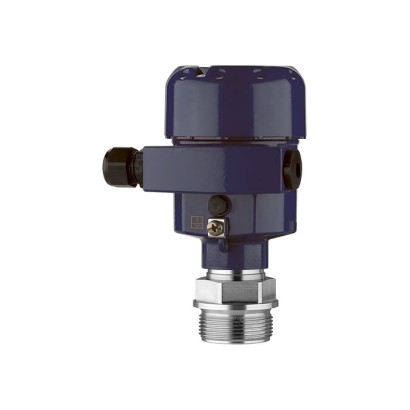
WIKA · Pressure measurement · Family CPT
Process transmitter
With capacitive ceramic measuring cell
Range
-1…100 bar
Output
FOUNDATION Fieldbus · 4-20 mA
Accuracy
0.05 % BFSL
Protection
IP66/IP67
CERoHSGOSTUkrSEPROREACHNACE[II 1G Ex ia IIC T6 ... T1 Ga][II 2G Ex ia IIC T6 ... T1 Gb][II 1D Ex ia IIIC T135 °C Da][II 2D Ex ia IIIC T135 °C Db][II 2D Ex tb ia IIIC T135 °C Db][Ex ia IIC T6 ... T1 Ga][Ex ia IIC T6 ... T1 Ga/Gb][Ex ia IIC T6 ... T1 Gb][Ex ia IIIC T135 °C Da][Ex ia IIIC T135 °C Db][Ex db ia IIC T6 ... T1 Ga/Gb][Ex db ia IIC T6 ... T1 Gb][Ex db ia tb ia IIIC T135 °C Db]ATEXIECEx
Price
On request
Depends on configuration
Description
With its 4 ... 20 mA, 4 ... 20 mA HART ® , PROFIBUS ® PA or FOUNDATION Fieldbus™ output signals, combined with either intrinsic safety or flameproof enclosure ignition protection type (in accordance with ATEX and IECEx), the model CPT-2x is ideally suited to applications with the highest demands on measurement technology.
Special features
- Ex protection per ATEX and IECEx
- For applications to SIL 2 (SIL 3)
- Dry ceramic measuring cell, high overload safety
- Seven different case variants
- Configuration via EDD (Electronic Device Description) and DTM (Device Type Manager) in accordance with the FDT (Field Device Tool) concept, e.g. PACTware
Identification
| Model | CPT-20 |
| Product family | CPT |
| Subcategory | Process transmitter |
Measuring range
| Pressure ranges | 0…0.1 bar · 0…0.4 bar · 0…1 bar · 0…2.5 bar · 0…5 bar · 0…10 bar · 0…25 bar · 0…60 bar · 0…100 bar · 0…0.4 psi · 0…1.5 psi · 0…5 psi · 0…15 psi · 0…30 psi · 0…150 psi · 0…300 psi · 0…1450 psi · 0…0.025 bar · -0.025…0.025 bar · -1…0 bar · -1…25 bar · -0.05…0.05 bar · -1…1.5 bar · -1…60 bar · -0.2…0.2 bar · -1…5 bar · -1…100 bar · -0.5…0.5 bar · -1…10 bar · 0…75 psi · 0…500 psi · 0…900 psi · -0.7…0.7 psi · -14.5…20 psi · -14.5…900 psi · -3…3 psi · -14.5…75 psi · -14.5…1450 psi · -7…7 psi · -14.5…150 psi · -14.5…0 psi · -14.5…300 psi |
Accuracy
| Accuracy class | 0.05 % BFSL |
| Accuracy standard | IEC 61298-2 |
| Safety integrity level (SIL) | SIL 2 (option up to SIL 3) |
Process conditions
| Process connection | G ½M20 x 1.5G ¼ A femaleG ½ A male¼ NPT female½ NPT maleG 1 AG 1 ½ AClamp 1"Clamp 1 ½"Clamp 2"DN 32DN 40DN 50DN 40, PN 40DN 50, PN 40DN 80, PN 402", 150 lbs3", 150 lbs |
| Process temperature | −20…+150 °C |
Electrical characteristics
| Output signal | FOUNDATION Fieldbus · 4-20 mA · 4-20 mA HART · PROFIBUS PA |
| Power supply | DC 9.6 ... 35 V |
| Electrical connection | M20 x 1.5 cable gland, ½ NPT cable gland, DIN 175301-803A, M12 x 1 (4-pin) |
Materials
| Case material | PBT, polyester, Die-casting AlSi10Mg, powder-coated on PE basis, Stainless steel 316L, aluminium, stainless steel, ABS |
| Wetted parts material | Stainless steel 316L, PVDF, Alloy C22 (2.4602), Alloy C276 (2.4819), Duplex (1.4462), Titanium grade 2, O3 ceramic, Sapphire ceramic with glass seam (> 99.9 % Al2), Sapphire ceramic |
| Sealing material | FKM, EPDM, FFKM |
Operating environment
| Ambient temperature | −40…+80 °C |
| IP rating | IP66/IP67 |
| Weight | 1.5 kg |
Certifications and approvals
| Certifications | CERoHSGOSTUkrSEPROREACHNACE |
| Explosion protection | [II 1G Ex ia IIC T6 ... T1 Ga][II 1/2G Ex ia IIC T6 ... T1 Ga/Gb][II 2G Ex ia IIC T6 ... T1 Gb][II 1D Ex ia IIIC T135 °C Da][II 2D Ex ia IIIC T135 °C Db][II 1/2G Ex db ia IIC T6 ... T1 Ga/Gb][II 2G Ex db ia IIC T6 ... T1 Gb][II 2D Ex tb ia IIIC T135 °C Db][Ex ia IIC T6 ... T1 Ga][Ex ia IIC T6 ... T1 Ga/Gb][Ex ia IIC T6 ... T1 Gb][Ex ia IIIC T135 °C Da][Ex ia IIIC T135 °C Db][Ex db ia IIC T6 ... T1 Ga/Gb][Ex db ia IIC T6 ... T1 Gb][Ex db ia tb ia IIIC T135 °C Db]ATEXIECEx |
Additional details
| Datasheet languages | EN, DE, FR, ES, PL, IT, NL, JA, ZH, RU, PT, TR, CS, KO, SV, DA, NO, FI |
Tables from datasheet
Gauge pressure
| bar | 0 ... 0.025 | 0 ... 0.1 | 0 ... 0.4 | 0 ... 1 |
|---|---|---|---|---|
| 0 ... 2.5 | 0 ... 5 | 0 ... 10 | 0 ... 25 | |
| 0 ... 60 | 0 ... 100 | |||
| psi | 0 ... 0.4 | 0 ... 1.5 | 0 ... 5 | 0 ... 15 |
| 0 ... 30 | 0 ... 75 | 0 ... 150 | 0 ... 300 | |
| 0 ... 500 | 0 ... 1,450 | |||
| Absolute pressure | ||||
| bar | 0 ... 0.1 | 0 ... 0.4 | 0 ... 1 | 0 ... 2.5 |
| 0 ... 5 | 0 ... 10 | 0 ... 25 | 0 ... 60 | |
| 0 ... 100 | ||||
| psi | 0 ... 0.4 | 0 ... 1.5 | 0 ... 5 | 0 ... 15 |
| 0 ... 30 | 0 ... 150 | 0 ... 300 | 0 ... 900 | |
| 0 ... 1,450 | ||||
| Vacuum and +/- measuring range | ||||
| bar | -0.025 ... +0.025 | -0.05 ... +0.05 | -0.2 ... +0.2 | -0.5 ... +0.5 |
| -1 ... 0 | -1 ... +1.5 | -1 ...+5 | -1 ...+10 | |
| -1 ...+25 | -1 ...+60 | -1 ...+100 | ||
| psi | -0.7 ... +0.7 | -3 ...+3 | -7 ...+7 | -14.5 ... 0 |
| -14.5 ...+20 | -14.5 ...+75 | -14.5 ...+150 | -14.5 ...+300 | |
| -14.5 ...+900 | -14.5 ... +1,450 |
Vacuum/overload safety
| Vacuum safety | Yes (from measuring range 0 ... 1 bar [0 ... 15 psi]) |
|---|---|
| Minimum pressure at 0 ... 0.025 bar [0 ... 0.4 psi] | -0.05 bar [-0.8 psi] |
| Minimum pressure at 0 ... 0.1 bar [0 .. 1.5 psi] | -0.2 bar [-3 psi] |
| Minimum pressure at 0 ... 0.4 bar [0 ... 5 psi] | -0.8 bar [-14 psi] |
| Overload safety | |
| Measuring range ≤ 1 bar [15 psi] | 35 times |
| Measuring range ≤ 10 bar [150 psi] | 9 times |
| Measuring range ≤ 60 bar [900 psi] | 3 times |
| Measuring range ≤ 100 bar [1,450 psi] | 2 times |
Output signals
| Signal types | ■ 4 ...20mA ■ 4 ... 20 mAwith a superimposed HART ® communication signal (option: SIL qualification) ■ HART ® specification: 7.3 ■ FOUNDATION™ Fieldbus ■ PROFIBUS ® PA ■ Slave electronics for electrical differential pressure (option: SIL qualification) |
|---|---|
| Load in Ω | (U B - U Bmin ) / 0.022 A |
| Dampening | 0.0 ... 999.9 s, adjustable After the set dampening time the instrument outputs 63 %of the applied pressure as output signal. |
| Step response time | < 80 ms (= dead time < 25 ms + rise time 10 ... 90 %<55ms) |
Accuracy specifications
| Accuracy at room temperature 1) | 0.05 %of span (option: 0.1 %or 0.2 %) |
|---|---|
| Adjustability | |
| Zero point | -20 ...+95 %(downwards, the adjustability is always limited by the minimum pressure of 0 bar abs. [0 psia]) |
| Span | -120 ...+120 %with a difference between zero point and span of a max. 120 %of the nominal measuring range (downwards, the adjustability is always limited by the minimum pressure of 0 bar abs. [0 psia]) |
| Turndown | Unlimited Max. turndown for SIL applications 10:1 |
| Non-linearity | Depending on the accuracy at room temperature |
| Accuracy at room temperature 0.05% | ≤ 0.05 %of span BFSL (IEC 61298-2) |
| Accuracy at room temperature 0.1% | ≤ 0.1 %of span BFSL (IEC 61298-2) |
| Accuracy at room temperature 0.2% | ≤ 0.2 %of span BFSL (IEC 61298-2) |
| Non-repeatability | Depending on the accuracy at room temperature |
| Accuracy at room temperature 0.05% | ≤ 0.05 %of span BFSL (IEC 61298-2) |
| Accuracy at room temperature 0.1% | ≤ 0.1 %of span BFSL (IEC 61298-2) |
| Accuracy at room temperature 0.2% | ≤ 0.2 %of span BFSL (IEC 61298-2) |
| Behaviour with turndown | |
| 1:1 ... 5:1 | No change in accuracy |
| > 5:1 | (basic accuracy / 5) x turndown |
| Long-term stability at reference conditions | |
| Measuring range 0 ... 0.025 bar [0.4 psi] | ■ < 0.1 %xturndown (1 year) ■ < 0.2 %xturndown (5 years) ■ < 0.4 %xturndown (10 years) |
| All other measuring ranges | ■ < 0.05 %xturndown (1 year) ■ < 0.1 %xturndown (5 years) ■ < 0.2 %xturndown (10 years) |
| Thermal change, zero point and span (reference temperature 20 °C | [68 °F]) |
| In compensated range 0 ... 100 °C [32 ... 212 °F] | < 0.075 %/ 10 K (max. 0.15 %) |
| Outside compensated range | < 0 °C [32 °F]: < 0.15 %/ 10 K > 100 °C [212 °F]: < 0.05 %/ 10 K |
| Thermal change of the current output 2) (reference temperature 20 °C [68 °F]) | < 0.05 %/ 10 K (max. 0.15 %) for 4 ... 20 mAoutput at -40 ...+80 °C [-40 ...+176 °F] |
View all (20)
Reference conditions (per IEC 61298-1)
| Temperature | 15 ... 25 °C [59 ... 77 °F] |
|---|---|
| Atmospheric pressure | 860 ... 1,060 mbar (86 ... 106 kPa, 12.5 ... 15.4 psig) |
| Air humidity | 45 ... 75 %r.h. |
| Characteristic curve determination | Terminal method per IEC 61298-2 |
| Curve characteristics | Linear |
| Reference mounting position | Vertical, diaphragm points downward |
| Signal type | Backlighting | |
|---|---|---|
| Inactive | Active | |
| 4 ... 20 mA | DC 9.6 ...35V | DC 16 ...35V |
| 4 ... 20 mA with a superimposed HART ® communication signal | DC 9.6 ...35V | DC 16 ...35V |
| FOUNDATION™ Fieldbus | DC 9 ...32V | DC 13.5 ...32V |
| PROFIBUS ® PA | DC 9.6 ...32V | DC 13.5 ...32V |
| Signal type | Backlighting | |
|---|---|---|
| Inactive | Active | |
| 4 ... 20 mA | DC 9.6 ...30V | DC 16 ...30V |
| 4 ... 20 mA with a superimposed HART ® communication signal | DC 9.6 ...30V | DC 16 ...30V |
| FOUNDATION™ Fieldbus | DC 9 ...24V (DC 9 ...17.5V Fisco) | DC 13.5 ...24V (DC 13.5 ...17.5V Fisco) |
| PROFIBUS ® PA | DC 9 ...24V (DC 9.6 ...17.5V Fisco) | DC 13.5 ...24V (DC 13.5 ...17.5V Fisco) |
Standard process connections for model CPT-20
| EN 837 | ■ G½ ■ M20 x 1.5 |
|---|---|
| ISO 228-1 | G¼Afemale, G½Amale |
| ANSI / ASME B1.20.1 | ¼NPTfemale, ½NPTmale |
Electrical connection
| Spring-loaded terminals | Wire cross-section | ■ Wire or strand: 0.2 ... 2.5 mm² (AWG 24 ... 14) ■ Strand with end splice: 0.2 ... 1.5 mm² (AWG 24 ... 16) |
|---|---|---|
| Cable glands M20 x 1.5 | ||
| Plastic, PA | Sealing | NBR |
| Cable diameter | ■ 5 ... 9 mm[0.2 ... 0.35 in] ■ 6 ... 12 mm[0.24 ... 0.47 in] ■ 10 ... 14 mm[0.39 ... 0.55 in] | |
| Brass, nickel-plated | Sealing | NBR |
| Cable diameter | 9 ... 13 mm[0.35 x 0.51 in] (for armoured cable) | |
| Stainless steel | Sealing | NBR |
| Cable diameter | 7 ... 12 mm[0.28 x 0.47 in] | |
| Cable glands ½ NPT | ||
| sealed with blind plug | ||
| Plastic, PA | Cable diameter | 5 ... 9 mm[0.2 ... 0.35 in] |
| Brass, nickel-plated | Cable diameter | 6 ... 12 mm[0.24 ... 0.47 in] |
| Brass, nickel-plated | Cable diameter | 9 ... 13 mm[0.35 x 0.51 in] (for armoured cable) |
| Angular connector DIN 175301- 803A with mating connector | Wire cross-section | Max.1.5mm 2 (AWG 16) |
| Ingress protection | IP65 1) | |
| Circular connector M12 x 1 (4-pin) without mating connector | Ingress protection | IP65 1) |
| Electrical safety | Reverse polarity protection |
Specifications
| Backlighting | Yes | |||
|---|---|---|---|---|
| Background | Grey, black digits | |||
| Upgradable | Yes (for order numbers, see 'Accessories') | |||
| Menu languages | German English French Spanish | Polish Italian Dutch | Japanese Chinese Russian | Portuguese Czech Turkish |
| Display size | 5-digit measured value display, adjustable (option: bar graph display) Max. 5 digits, size 7 x 13 mm[0.28 x 0.51 in] | |||
| Ingress protection per IEC/EN 60529 | ■ IP20 (loose) ■ IP40 (built-in without cover) | |||
| Material | Case from ABS, window from polyester film |
Operating conditions
| Permissible temperature ranges | Pay attention to restrictions to temperature ranges with Ex approvals |
|---|---|
| Ambient | ■ -20 ...+70 °C [-4 ... 158 °F] (with digital display) ■ -40 ...+80 °C [-40 ... 176 °F] (without digital display) |
| Medium | see sealing material |
| Storage | -60 ...+80 °C [-76 ... 176 °F] |
| Restrictions to medium temperature due to sealing material | For oxygen applications max. 60 °C [140 °F] |
| FKM | -20 ...+130 °C (option: -20 ...+150 °C) [-4 ...+266 °F (option: -4 ...+302 °F)] |
| EPDM | -40 ...+130 °C (option: -40 ...+150 °C) [-40 ...+266 °F (option: -40 ...+302 °F)] |
| FFKM | -20 ...+130 °C (option: -20 ...+150 °C) [-4 ...+266 °F (option: -4 ...+302 °F)] |
Operating conditions
| Vibration resistance per EN 60068-2-6 (vibration under resonance) | ■ 4 g (5 ... 200 Hz) per GL characteristic curve 2 ■ 0.75 g in accordance with GLcharacteristic curve 1 (double chamber case from stainless steel) |
|---|---|
| Shock resistance per IEC 60068-2-27 (mechanical shock) | ■ 50 g (2.3 ms) ■ 2 g (for double chamber case, cast stainless steel) |
| Instrument safety | |
| Ingress protection per IEC/EN 60529 | ■ IP66/67 ■ IP66/IP68 (0.2 bar) for absolute pressure sensors ■ Option: IP66/IP68 (1 bar) or IP68 (25 bar) |
| Electrical safety | Overvoltage category III, protection class II |
| SIL per IEC 61508:2010 | ■ Single-channel operation up to SIL 2 ■ Multi-channel operation (homogeneous, redundant) up to SIL 3 |
| Logo | Description | Country |
|---|---|---|
| EU declaration of conformity | European Union | |
| Zone 21 dust [II 2D Ex tb ia IIIC T135 °C Db] IECEx Hazardous areas - Ex i Zone 0 gas [Ex ia IIC T6 ...T1 Ga] mounting to zone 0 gas [Ex ia IIC T6 ...T1 Ga/Gb] | ||
| Zone 1 gas Zone 1 gas [Ex ia IIC T6 ...T1 Gb] Zone 20 dust [Ex ia IIIC T135 °C Da] Zone 21 dust [Ex ia IIIC T135 °C Db] - Ex d Zone 1 gas mounting to zone 0 gas [Ex db ia IIC T6 ...T1 Ga/Gb] Zone 2 gas [Ex db ia IIC T6 ...T1 Gb] Zone 21 dust [Ex db ia tb ia IIIC T135 °C Db] | International | |
| GOST Metrology, measurement technology | ||
| Russia | ||
| UkrSEPRO Metrology, measurement technology | Ukraine |
| Logo | Description | |
|---|---|---|
| SIL 2 (option) 1) Functional safety | ||
| - | NAMUR recommendations | |
| NE21 | Electromagnetic compatibility of equipment | |
| NE43 | Signal level for failure information | |
| NE53 | Compatibility of field instruments | |
| NE107 | Self-monitoring and diagnostics |
Standard process connections for model CPT-20
| | EN 837 | G½ |
|---|---|---|
| | ISO 228-1 | G¼Afemale, G½male |
| | ISO 228-1 | G¼Afemale, G½male (PVDF) |
| | EN 837 | G½(volume reduced) |
| | ANSI / ASME B1.20.1 | ¼NPTfemale, ½NPTmale |
| | EN 837 | M20 x 1.5 |
Flush process connections for model CPT-21
| | ISO 228-1 | G½ |
|---|---|---|
| | DIN 3852-E | G¾ |
| | ISO 228-1 | G1A |
| | DIN 3852-A | G1½ |
| | DIN 3852-A-B | G1½A |
| | ANSI / ASME B1.20.1 | 1½NPT |
Aseptic process connections for model CPT-21
| | DIN 32676, ISO 2552 | Clamp 2" |
|---|---|---|
| | DIN 11851 with grooved union nut | Form F, DN 40 |
| | EN 1092-1 collar, DIN 2527 | DRD, DN 25 |
| | VARIVENT ® | DN 32 |
| | Threaded pipe connection per DIN 11851 | DN 40 |
| | Threaded pipe connection per DIN 11851 | DN 50 |
| | Threaded pipe connection per DIN 11864-1 | DN 50 |
| mm | DN | PN | D | b | k | d2 | d4 | f | H |
|---|---|---|---|---|---|---|---|---|---|
| 1 | 40 | 40 | 150 | 18 | 110 | 4xø18 | 88 | 3 | 50 |
| 50 | 40 | 165 | 20 | 125 | 4xø18 | 102 | 3 | 50 | |
| 80 | 40 | 200 | 24 | 160 | 8xø18 | 138 | 3 | 51 | |
| 2 | 2' | 150 lbs | 152,4 | 19,1 | 120,7 | 4xø19,1 | 91,9 | 3,2 | 51 |
| 3' | 150 lbs | 190,5 | 23,9 | 152,4 | 8xø19,1 | 127 | 3,2 | 51 |
| inch | DN | PN | D | b | k | d2 | d4 | f | H |
|---|---|---|---|---|---|---|---|---|---|
| 1 | 40 | 40 | 5.91" | 0.71" | 4.33" | 4xø 0.71" | 3.46" | 0.12" | 1.97" |
| 50 | 40 | 6.50" | 0.79" | 4.92" | 4xø 0.71" | 4.02" | 0.12" | 1.97" | |
| 80 | 40 | 7.87" | 0.95" | 6.30" | 8xø 0.71" | 5.43" | 0.12" | 2.01" | |
| 2 | 2' | 150 lbs | 6" | 0.75" | 4.75" | 4xø 0.75" | 3.62" | 0.13" | 2.01" |
| 3' | 150 lbs | 7.5" | 0.94" | 6" | 8xø 0.75" | 5' | 0.13" | 2.01" |
Flanges for model CPT-21
| | DIN 2501 |
|---|---|
| | ASME B16.5 |
Industry
Oil & Gas
Chemical and petrochemical industries
Industry
Chemistry / Pharma
Process engineering
Industry
Water supply
Water and wastewater
Couldn't find the answer in the documentation? An engineer will reply within a business day.
Ask an engineer →All variants · Article table
1 standard articles of family CPT
If you know the code — pick directly. If not — use the configurator in mode “01”.
Stock:
SKUConfigurationPriceStockAction
CPT-20-ZZZ-KIZZZ-HR-BG125-GDUDAAC1-ZZZ-ZZProcess connection type: 0 · Electrical approval: Z · Ignition protection type: ZZ+ 23 moreOn requestOn orderRequest →
Showing 1 of 1. Price on request — an engineer will quote your configuration.