
WIKA · Pressure measurement · Family 736
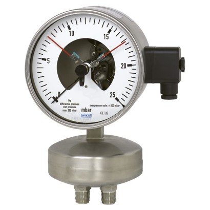
Differential pressure gauge with switch contacts
For very low differential pressures, from 2.5 mbar, with capsule element
Range
0…1000 mbar
Output
Magnetic snap-action contact
Accuracy
1.6
Protection
IP66
CERoHSCRNEAC
Price
On request
Depends on configuration
Description
The model 736.51 capsule pressure gauge is based upon the proven capsule measuring system and is suitable for very low pressures. On pressurisation, the expansion of the capsule element, proportional to the incident pressure, is transmitted to the movement and indicated.
For the version with switch contact, magnetic snap-action contacts, reed switches, and electronic contacts are available. For triggering programmable logic controllers (PLC), electronic contacts and reed switches can be used.
Fig. left: Model 736.51, NS 100
Fig. right: Model 736.51, NS 160 with switch contacts
Special features
- Differential pressure measuring ranges from 0 … 2.5 mbar
- Ingress protection IP66
- Case and wetted parts from stainless steel
- Version with switch contact for PLC applications
Identification
| Model | 736.51 |
| Product family | 736 |
| Subcategory | Capsule element differential pressure gauge |
Measuring range
| Pressure ranges | 0…2.5 mbar · 0…4 mbar · 0…6 mbar · 0…10 mbar · 0…25 mbar · 0…40 mbar · 0…16 mbar · 0…60 mbar · 0…100 mbar · 0…160 mbar · 0…0.5 kPa · 0…1 kPa · 0…1.6 kPa · 0…2.5 kPa · 0…4 kPa · 0…6 kPa · 0…10 kPa · 0…250 mmH2O · 0…1000 mmH2O · 0…5 inH2O · 0…10 inH2O · 0…15 inH2O · 0…20 inH2O · 0…25 inH2O · 0…600 mbar · 0…1000 mbar · 0…25 mm H2O · 0…40 mm H2O · 0…60 mm H2O · 0…100 mm H2O · 0…160 mm H2O · 0…250 mm H2O · 0…400 mm H2O · 0…600 mm H2O · 0…1000 mm H2O · 0…5 in H2O · 0…10 in H2O · 0…15 in H2O · 0…20 in H2O · 0…25 in H2O · 0…30 in H2O · 0…40 in H2O · 0…0.5 mbar · 0…1 mbar · 0…1.6 mbar · 0…30 mbar · 0…25 mmH2O · 0…40 mmH2O · 0…60 mmH2O · 0…100 mmH2O · 0…160 mmH2O · 0…400 mmH2O · 0…600 mmH2O · 0…30 inH2O · 0…40 inH2O |
Accuracy
| Accuracy class | 1.6 |
| Accuracy standard | EN 837-1 |
Process conditions
| Process connection | G ½ B½ NPTEN 837-1ANSI/B1.20.1Without2xG1/2B2x1/2NPT |
| Process temperature | −20…+60 °C |
Electrical characteristics
| Output signal | Magnetic snap-action contact · Electronic contact (PNP transistor) · Reed switch · Reed contact |
| Power supply | DC 10 ... 30 V |
| Electrical connection | Cable socket, M20 x 1.5 |
| Switching function | Normally open, Normally closed, Change-over |
| Switching contacts | 3 |
Materials
| Case material | Stainless steel 1.4571 (316 Ti) |
| Wetted parts material | Stainless steel 1.4571, Aluminium, Laminated safety glass, PUR, PTFE, NBR |
| Sealing material | PTFE, NBR |
Operating environment
| Ambient temperature | −20…+60 °C |
| IP rating | IP66 |
| Weight | 1.7 kg |
Certifications and approvals
| Certifications | CERoHSCRNEAC |
Additional details
| Dial size | 100 mm |
| Datasheet languages | EN, DE, ES, FR |
Tables from datasheet
| Pressure gauge | Switch contact | |||
|---|---|---|---|---|
| Without | Magnetic snap-action contact (model 821) | Electronic contact (model 830 E) | Reed contact (model 851) | |
| Model 736.51, with capsule | x | |||
| element | x | |||
| x | ||||
| x |
Basic information
| Nominal size | ■ Ø100mm ■ Ø160mm |
|---|---|
| Window | Laminated safety glass |
| Case | |
| Design | Safety level 'S1' per EN 837-1:With blow-out device |
| Material | Stainless steel 1.4571 (316 Ti) |
| Ring | Bayonet ring, stainless steel |
| Mounting | ■ Without ■ Panel mounting flange, stainless steel ■ Panel mounting flange, polished stainless steel ■ Triangular profile ring with mounting bracket, polished stainless steel ■ Surface mounting flange, stainless steel |
| Case filling | ■ Without ■ Silicone oil |
| Movement | Stainless steel |
Measuring element
| Type of measuring element | Capsule element |
|---|---|
| Material | Stainless steel 1.4571 |
| Leak tightness | Helium tested, leakage rate: < 5∙10 -3 mbar l/s |
Accuracy specifications
| Accuracy class | ■ 1.6 ■ 1.0 |
|---|---|
| Temperature error | On deviation from the reference conditions at the measuring system: max. ±0.6 %/10 K of full scale value |
| Zero point setting | Via adjustment appliance at case circumference at 12 o'clock, stainless steel (wetted) |
| Reference conditions | |
| Ambient temperature | +20 °C |
View all (16)
| Scale range | ||||
|---|---|---|---|---|
| mbar | ||||
| 0 ... 2.5 | 0 ... 4 | 0 ... 6 | 0 ... 10 | 0 ... 16 |
| 0 ... 25 | 0 ... 40 | 0 ... 60 | 0 ... 100 | |
| 0 ... 0.5 0 ... 6 | 0 ... 1 0 ... 10 | 0 ... 1.6 | 0 ... 2.5 | 0 ... 4 |
| 0 ... 25 | 0 ... 40 | 0 ... 60 | 0 ... 100 | 0 ... 160 |
| mmH 2 O | 0 ... 1,000 | |||
| 0 ... 250 in H 2 O | 0 ... 400 | 0 ... 600 | ||
| 0 ... 5 | 0 ... 10 | 0 ... 15 | 0 ... 20 | 0 ... 25 |
| 0 ... 25 | 0 ... 30 | 0 ... 40 |
Output signal: Contact model 821, magnetic snap-action contact
| Connection method | Magnetic snap-action contact |
|---|---|
| Switching technology | ■ No control unit and no supply voltage required ■ Direct switching up to 250 V, 1 A |
| Number of switch contacts | |
| Span ≥ 25 mbar ...< 40 mbar 1) | Max. 2 switch contacts |
| Span ≥ 40 mbar | Max. 3 switch contacts 2) |
| Switching function | ■ Separate circuits with ≥ 2 switches ■ Cable break monitoring with parallel resistance (47 kΩ or 100 kΩ) The switching function of each switch is indicated by index 1, 2 or 3 |
| Model 821.1 | Normally open (clockwise pointer motion) |
| Model 821.2 | Normally closed (clockwise pointer motion) |
| Model 821.3 | Change-over; one contact breaks and one contact makes simultaneously when pointer reaches set point |
| Switch point setting | Set pointers of the contact pressure gauges are freely adjustable over the full scale range |
| Setting range (recommended) | 25 ... 75 %of span (0 ... 100 %onrequest) |
| Distance between switch points | Recommended minimum distance between 2 contacts: 20 %of span |
| Switch hysteresis | 2 ... 5 %(typical) |
| Switching current | 0.02 ... 0.3 A (resistive load) Permissible switch-on and switch-off current: ≤ 0.5 A |
| Switching voltage | AC/DC 24 ...250V |
| Switching power | |
| Unfilled instruments | ≤ 30 W, ≤ 50VA |
| Filled instruments | ≤ 20 W, ≤ 20VA |
| Contact material | ■ Silver-nickel, gold-plated |
| Switching voltage | Unfilled instruments | Filled instruments | ||||
|---|---|---|---|---|---|---|
| Resistive load | Inductive load | Resistive load | Inductive load | |||
| Direct cur - rent | Alternating current | cos ϕ>0.7 | Direct cur - rent | Alternating current | cos ϕ>0.7 | |
| DC 220 V / AC 230 V | 100mA | 120mA | 65mA | 65mA | 90mA | 40mA |
| DC 110 V / AC 110 V | 200mA | 240mA | 130mA | 130mA | 180mA | 85mA |
| DC 48 V / AC 48 V | 300mA | 450mA | 200mA | 190mA | 330mA | 130mA |
| DC 24 V / AC 24 V | 400mA | 600mA | 250mA | 250mA | 450mA | 150mA |
Output signal: Contact model 830 E, electronic contact
| Connection method | Electronic contact (PNP transistor) |
|---|---|
| Switching technology | ■ For direct triggering of a programmable logic controller (PLC) ■ Long service life due to non-contact sensor ■ Low influence on the indication accuracy ■ Fail-safe switching at high switching frequency ■ Insensitive to corrosion |
| Number of switch contacts | |
| Span ≥ 25 mbar | Max. 3 switch contacts |
| Switching function | Contact versions: ■ 2-wire system ■ 3-wire system The switching function of each switch is indicated by index 1 or 2 |
| Model 830 E.1 | Normally open (clockwise pointer motion) |
| Model 830 E.2 | Normally closed (clockwise pointer motion) |
| Setting range (recommended) | 10 ... 90 %of span (0 ... 100 %onrequest) |
| Distance between switch points | Up to 2 contacts can be set to an identical set point. For a version with 3 contacts this is not possible.The left (1st) or right (3rd) contact may not be set to the same set point as the oth- er 2 contacts.The required displacement is approx. 30°, optionally to the right or to the left. |
| Switching current | ≤ 100mA |
| Switching voltage | DC 10 ...30V |
Output signal: Contact model 851, reed switch
| Connection method | Bistable reed switch |
|---|---|
| Switching technology | ■ No control unit and no supply voltage required ■ Direct switching up to 250 V, 1 A ■ For direct triggering of a programmable logic controller (PLC) ■ Free from wear as without contact |
| Number of switch contacts | |
| NS 100 | Max. 2 switch contacts |
| NS 160 | 1 switch contact |
| Switching function | ■ Separate circuits with ≥ 2 switches ■ Cable break monitoring with parallel resistance (47 kΩ or 100 kΩ) The switching function of each switch is indicated by index 1, 2 or 3 |
| Model 851.3 | Change-over; one contact breaks and one contact makes simultaneously when pointer reaches set point |
| Switch point setting | Set pointers of the contact pressure gauges are freely adjustable over the full scale range |
| Setting range (recommended) | 10 ... 90 %of span |
| Distance between switch points | When using two contacts, these cannot be set to the same point. Depending on the switch- ing function, a minimum clearance of 15 ... 30° is required. |
| Switch hysteresis | 3 ...5% |
| Switching current | AC/DC 1 A |
| Switching voltage 1) | AC/DC 250V |
| Switching power | 60 W, 60VA |
| Contact material | Rhodium |
| Transport current | AC/DC 2 A |
| Inductive load cosϕ | 1 |
| Contact resistance (static) | 100mΩ |
| Insulation resistance | 109Ω |
| Breakdown voltage | DC 1,000V |
| Switching time incl. contact chatter | 4.5 ms |
Electrical connections 1)
| Connection type | ■ Cable socket, black PerVDE 0110 insulation group C/250V Cable gland M20 x 1.5 ■ Connector (instead of cable socket) |
|---|---|
| Wire cross-section | 6 screw terminals + PE for 2.5 mm² |
| Cable diameter | →See dimensions |
| Pin assignment | Connection details are given on the product label of the instrument. Connection termi- nals and ground terminals are appropriately marked. |
| Material | PA 6 (polyamide) |
Operating conditions
| Medium temperature | +60 °C [+140 °F] maximum |
|---|---|
| Ambient temperature | -20 ...+60 °C [-4 ... 140 °F] |
| Storage temperature | -20 ...+60 °C [-4 ... 140 °F] |
| Pressure limitation | |
| Steady | Full scale value |
| Fluctuating | 0.9 x full scale value |
| Ingress protection of the complete instrument | IP66 per IEC/EN 60529 |
| Logo | Description | Region |
|---|---|---|
| EU declaration of conformity | European Union | |
| EMCdirective | ||
| - | CRN Safety (e.g. electr. safety, overpressure, ...) | Canada |
| Logo | Description | Region |
|---|---|---|
| EAC (option) Pressure equipment directive | Eurasian Economic Community | |
| GOST Metrology, measurement technology | Russia | |
| KazInMetr Metrology, measurement technology | Kazakhstan | |
| - | MTSCHS Permission for commissioning | Kazakhstan |
| BelGIM Metrology, measurement technology | Belarus | |
| UkrSEPRO Metrology, measurement technology | Ukraine | |
| Uzstandard Metrology, measurement technology | Uzbekistan |
Certificates
| Certificates | ■ 2.2 test report per EN 10204 (e.g. state-of-the-art manufacturing, indication accuracy) ■ 3.1 inspection certificate per EN 10204 (e.g. indication accuracy) |
|---|---|
| Recommended calibration interval | 1 year (dependent on conditions of use) |
| NS | Dimensions in mm[in] | Weight in kg [lb] | |||||||||
|---|---|---|---|---|---|---|---|---|---|---|---|
| a | b | D 1 | D 2 | d | e | G | h ±1 | X | SW | ||
| 100 | 15.5 [0.61] | 49.5 [1.95] | 101 [3.98] | 99 [3.90] | 133 [5.24} | 17.5 [0.69] | G½B | 170 [6.69] | 37 [1.46] | 22 [0.87] | 1.70 [3.75] |
| 160 | 15.5 [0.61] | 49.5 [1.95] | 161 [6.34] | 159 [6.26] | 133 [5.24} | 17.5 [0.69] | G½B | 200 [7.87] | 37 [1.46] | 22 [0.87] | 2.20 [4.85] |
| Model | Description | Order number | |
|---|---|---|---|
| 910.17 | Sealings →See data sheet AC 09.08 | - | |
| IV3x, IV5x | Valve manifold for differential pressure measuring instruments →See data sheet AC 09.23 | - | |
| - | Diaphragm seal | On request |
Industry
Oil & Gas
Process industry: Chemical industry, petrochemical industry, on/offshore
Industry
Machinery
Differential pressure measurement at measuring locations with very low differential pressures, for transparent, gaseous, dry, clean, oil- and grease-free media, also in aggressive environments · Filter monitoring in ventilation and heating systems or in overpressure and clean rooms · Differential pressure controlled monitoring of ventilator and blast pressures
Couldn't find the answer in the documentation? An engineer will reply within a business day.
Ask an engineer →