
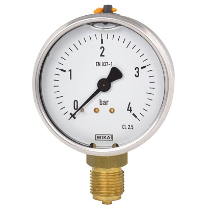
Bourdon tube pressure gauge, copper alloy
Description
The liquid-filled model 113.53 mechanical Bourdon tube pressure gauge is constructed with a case from stainless steel and wetted parts from copper alloy.
WIKA manufactures and qualifies the pressure gauge in accordance with the standards EN 837-1 and ASME B40.100. As a safety function, this instrument has a blow-out device. In the event of a failure, overpressure can escape there.
Due to the case filling, the pressure element and movement are efficiently damped. Therefore, these instruments are particularly suited to measuring locations with high dynamic loads, such as fast load cycles or vibrations.
For further approvals, see page 6
The cases of the model 113.53 are available in nominal sizes of 40 [1 ½"], 80 [3"] and 100 [4"] and fulfil IP65 ingress protection. With an accuracy of class 2.5, this pressure gauge is suitable for a wide range of applications in industry.
For mounting in control panels, the pressure gauges with a back mount process connection can be fitted with a mounting flange or with a triangular profile ring and mounting bracket.
Special features
- Vibration and shock resistant
- Robust design
Build a 113.53 for your task
The article number is assembled automatically. If unsure — ask an engineer; we'll match the line's parameters.
- Nominal size040 mm
- Unit of outer Scalebar
- Measuring rangegauge pressure range
- Scale range0...1 bar
- 2nd Scale or Special Scalewithout
- Process connection—
- Connector location—
- Mounting flange/bracketwithout
- Restrictorwithout
- Accuracy classclass 2.5
- case fillingglycerine
- Certificateswithout
Finish your configuration
Select every option to submit the request.
| Model | 113.53 |
| Product family | 113 |
| Subcategory | Mechanical pressure gauge |
| Pressure ranges | 0…1 bar · 0…1.6 bar · 0…2.5 bar · 0…4 bar · 0…6 bar · 0…10 bar · 0…16 bar · 0…25 bar · 0…40 bar · 0…60 bar · 0…100 bar · 0…160 bar · 0…200 bar · 0…250 bar · 0…315 bar · 0…400 bar · 0…600 bar · 0…100 kPa · 0…200 kPa · 0…250 kPa · 0…400 kPa · 0…600 kPa · 0…800 kPa · 0…1000 kPa · 0…1600 kPa · 0…2500 kPa · 0…4000 kPa · 0…6000 kPa · 0…8000 kPa · 0…10000 kPa · 0…16000 kPa · 0…20000 kPa · 0…25000 kPa · 0…31500 kPa · 0…40000 kPa · 0…60000 kPa · 0…15 psi · 0…30 psi · 0…60 psi · 0…100 psi · 0…150 psi · 0…160 psi · 0…200 psi · 0…300 psi · 0…400 psi · 0…500 psi · 0…600 psi · 0…800 psi · 0…1000 psi · 0…1500 psi · 0…2000 psi · 0…3000 psi · 0…4000 psi · 0…5000 psi · 0…6000 psi · 0…7500 psi · 0…0.1 MPa · 0…0.16 MPa · 0…0.25 MPa · 0…0.4 MPa · 0…0.6 MPa · 0…1 MPa · 0…1.6 MPa · 0…2.5 MPa · 0…4 MPa · 0…6 MPa · 0…10 MPa · 0…20 MPa · 0…25 MPa · 0…31.5 MPa · 0…40 MPa · 0…60 MPa · -1…0 bar · -1…9 bar · -1…0.6 bar · -1…15 bar · -1…1.5 bar · -1…24 bar · -1…3 bar · -1…30 bar · -1…5 bar · -1…40 bar · -100…0 kPa · -100…500 kPa · -100…60 kPa · -100…900 kPa · -100…100 kPa · -100…1500 kPa · -100…150 kPa · -100…2400 kPa · -100…300 kPa · -100…3000 kPa · -0.1…0 MPa · -0.1…0.5 MPa · -0.1…0.06 MPa · -0.1…0.9 MPa · -0.1…0.15 MPa · -0.1…1.5 MPa · -0.1…0.3 MPa · -0.1…2.4 MPa · 0…16 MPa · -30…0 inHg · -30…15 inHg · 0…1 kg/cm2 · 0…1.6 kg/cm2 · 0…2.5 kg/cm2 · 0…4 kg/cm2 · 0…6 kg/cm2 · 0…10 kg/cm2 · 0…16 kg/cm2 · 0…25 kg/cm2 · 0…40 kg/cm2 · 0…60 kg/cm2 · 0…100 kg/cm2 · 0…160 kg/cm2 · 0…200 kg/cm2 · 0…250 kg/cm2 · 0…315 kg/cm2 · 0…400 kg/cm2 · 0…600 kg/cm2 · -1…0 kg/cm2 · -1…5 kg/cm2 · -1…0.6 kg/cm2 · -1…9 kg/cm2 · -1…1 kg/cm2 · -1…15 kg/cm2 · -1…1.5 kg/cm2 · -1…24 kg/cm2 · -1…3 kg/cm2 · -1…30 kg/cm2 · 0…1 kg/cm² · 0…1.6 kg/cm² · 0…2.5 kg/cm² · 0…4 kg/cm² · 0…6 kg/cm² · 0…10 kg/cm² · 0…16 kg/cm² · 0…25 kg/cm² · 0…40 kg/cm² · 0…60 kg/cm² · 0…100 kg/cm² · 0…160 kg/cm² · 0…200 kg/cm² · 0…250 kg/cm² · 0…315 kg/cm² · 0…400 kg/cm² · 0…600 kg/cm² · -1…5 kg/cm² · -1…9 kg/cm² · -1…15 kg/cm² · -1…24 kg/cm² · -1…30 kg/cm² |
| Accuracy class | 2.5 |
| Accuracy standard | EN 837-1, ASME B40.100 |
| Process connection | G ⅛ BG ¼ BG ½ BM10 x 1M12 x 1.5M20 x 1.5R ⅛R ¼R ½⅛ NPT¼ NPT½ NPTG⅛B, male threadG¼B, male threadG½B, male threadM10 x 1, male threadM12 x 1.5, male threadM20 x 1.5, male threadR ⅛, male threadR ¼, male threadR ½, male thread⅛NPT, male thread¼NPT, male thread½NPT, male threadG 1/8 BG 1/4 BR 1/8R 1/41/8 NPT1/4 NPTG 1/2 BR 1/21/2 NPT |
| Process temperature | −20…+100 °C |
| Case material | Stainless steel |
| Wetted parts material | Copper alloy |
| Ambient temperature | −20…+60 °C |
| IP rating | IP65 |
| Weight | 0.5 kg |
| Certifications | CEPEDCRNPressure Equipment Directive |
| Dial size | 100 mm |
| Datasheet languages | EN, DE |
| Standard | ■ EN 837-1 ■ ASME B40.100 | |
|---|---|---|
| → For information on the 'Selection, installation, handling and operation of pres - sure gauges', see technical information IN 00.05. | ||
| Nominal size (NS) | ■ Ø40 mm[1 ½"] ■ Ø80 mm[3"] ■ Ø100 mm[4"] | |
| Connection location | ■ Lower mount (radial) ■ Centre back mount | |
| Window | Polycarbonate | |
| Case | ||
| Design | NS 40 [1 ½"] | Safety level 'S2' per EN 837-1: with blow-out device |
| NS 80 [3"], 100 [4"] | Safety level 'S1' per EN 837-1: with blow-out device With scale ranges ≤ 0 ... 16 bar [≤ 0 ... 200 psi], the filling plug can be vented and resealed for internal pressure compensation | |
| Material | Stainless steel, natural finish | |
| Ring | Crimp ring, stainless steel | |
| Mounting | ■ Without ■ Panel mounting flange, stainless steel 1) ■ Triangular profile ring with mounting bracket, stainless steel 1) | |
| Case filling | ■ Glycerine 2) | |
| Movement | Copper alloy |
| bar | |
|---|---|
| 0 ... 1 | 0 ... 60 |
| 0 ... 1.6 | 0 ... 100 |
| 0 ... 2.5 | 0 ... 160 |
| 0 ... 4 | 0 ... 200 |
| 0 ... 6 | 0 ... 250 |
| 0 ... 10 | 0 ... 315 |
| 0 ... 16 | 0 ... 400 |
| 0 ... 25 | 0 ... 600 |
| 0 ... 40 | - |
| 0 ... 100 | 0 ... 6,000 |
|---|---|
| 0 ... 200 | 0 ... 8,000 |
| 0 ... 250 | 0 ... 10,000 |
| 0 ... 400 | 0 ... 16,000 |
| 0 ... 600 | 0 ... 20,000 |
| 0 ... 800 | 0 ... 25,000 |
| 0 ... 1,000 | 0 ... 31,500 |
| 0 ... 1,600 | 0 ... 40,000 |
| 0 ... 2,500 | 0 ... 60,000 |
| 0 ... 4,000 | - |
| psi | |
|---|---|
| 0 ... 15 | 0 ... 600 |
| 0 ... 30 | 0 ... 800 |
| 0 ... 60 | 0 ... 1,000 |
| 0 ... 100 | 0 ... 1,500 |
| 0 ... 150 | 0 ... 2,000 |
| 0 ... 160 | 0 ... 3,000 |
| 0 ... 200 | 0 ... 4,000 |
| 0 ... 300 | 0 ... 5,000 |
| 0 ... 400 | 0 ... 6,000 |
| 0 ... 500 | 0 ... 7,500 |
View all (20)
| 0 ... 1 | 0 ... 60 |
|---|---|
| 0 ... 1.6 | 0 ... 100 |
| 0 ... 2.5 | 0 ... 160 |
| 0 ... 4 | 0 ... 200 |
| 0 ... 6 | 0 ... 250 |
| 0 ... 10 | 0 ... 315 |
| 0 ... 16 | 0 ... 400 |
| 0 ... 25 | 0 ... 600 |
| 0 ... 40 | - |
| 0 ... 0.1 | 0 ... 6 |
|---|---|
| 0 ... 0.16 | 0 ... 10 |
| 0 ... 0.25 | 0 ... 16 |
| 0 ... 0.4 | 0 ... 20 |
| 0 ... 0.6 | 0 ... 25 |
| 0 ... 1 | 0 ... 31.5 |
| 0 ... 1.6 | 0 ... 40 |
| 0 ... 2.5 | 0 ... 60 |
| 0 ... 4 | - |
| bar | |
|---|---|
| -1 ... 0 | -1 ...+9 |
| -1 ... +0.6 | -1 ...+15 |
| -1 ... +1.5 | -1 ...+24 |
| -1 ...+3 | -1 ...+30 |
| -1 ...+5 | -1 ...+40 |
| -100 ... 0 | -100 ...+500 |
|---|---|
| -100 ...+60 | -100 ...+900 |
| -100 ...+100 | -100 ... +1,500 |
| -100 ...+150 | -100 ... +2,400 |
| -100 ...+300 | -100 ... +3,000 |
| psi | |
|---|---|
| -30 inHg ... 0 | -30 inHg ...+15 |
| -1 ... 0 | -1 ...+5 |
|---|---|
| -1 ... +0.6 | -1 ...+9 |
| -1 ...+1 | -1 ...+15 |
| -1 ... +1.5 | -1 ...+24 |
| -1 ...+3 | -1 ...+30 |
| -0.1 ... 0 | -0.1 ... +0.5 |
|---|---|
| -0.1 ... +0.06 | -0.1 ... +0.9 |
| -0.1 ... +0.15 | -0.1 ... +1.5 |
| -0.1 ... +0.3 | -0.1 ... +2.4 |
| Process connection | |
|---|---|
| Standard | ■ EN 837-1 ■ ISO 7 ■ ANSI/B1.20.1 |
| Size | |
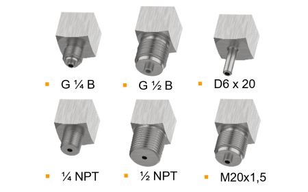
| EN 837-1 | ■ G⅛B,male thread ■ G¼B,male thread ■ G½B,male thread ■ M10 x 1, male thread ■ M12 x 1.5, male thread ■ M20 x 1.5, male thread |
| ISO 7 | ■ R ⅛, male thread ■ R ¼, male thread ■ R ½, male thread |
| ANSI/B1.20.1 | ■ ⅛NPT, male thread ■ ¼NPT, male thread ■ ½NPT, male thread |
| Restrictor | ■ Without ■ ∅0.5 mm[0.02"], copper alloy ■ ∅0.3 mm[0.012"], copper alloy |
| Material (wetted) | |
| Process connection | Copper alloy |
| Bourdon tube | Copper alloy |
| Medium temperature | |
|---|---|
| Instruments with glycerine filling | -20 ...+100 °C [-4 ...+212 °F] |
| Instruments with silicone oil filling | -40 ...+100 °C [-40 ...+212 °F] |
| Ambient temperature | |
| Instruments with glycerine filling | -20 ...+60 °C [-4 ...+140 °F] |
| Instruments with silicone oil filling | -40 ...+60 °C [-40 ...+140 °F] |
| Pressure limitation | |
| Steady | 3/4 x full scale value |
| Fluctuating | 2/3 x full scale value |
| Short time | Full scale value |
| Ingress protection per IEC/EN 60529 | IP65 |
| Logo | Description | Region |
|---|---|---|
| EU declaration of conformity | European Union | |
| - | CRN Safety (e.g. electr. safety, overpressure, ...) | Canada |
| Logo | Description | Region |
|---|---|---|
| PAC Kazakhstan Metrology, measurement technology | Kazakhstan | |
| - | PAC Ukraine Metrology, measurement technology | Ukraine |
| PAC Uzbekistan Metrology, measurement technology | Uzbekistan | |
| - | PAC China Metrology, measurement technology | China |
| Logo | Description |
|---|---|
| - | Pressure Equipment Directive (PED) for maximum allowable pressure PS ≤ 200 bar |
| - | Suitability of wetted materials for drinking water in accordance with the European 4MS initiative |
| Certificates | ■ 2.2 test report per EN 10204 (e.g. state-of-the-art manufacturing, indication accuracy) ■ 3.1 inspection certificate per EN 10204 (e.g. indication accuracy) ■ PCA calibration certificate, traceable and accredited in accordance with ISO/IEC 17025 ■ Calibration certificate by a national accreditation body, traceable and accredited in accordance with ISO/IEC 17025 on request |
|---|---|
| Recommended calibration interval | 1 year (dependent on conditions of use) |
| NS | G | Dimensions in mm[in] | |||||||
|---|---|---|---|---|---|---|---|---|---|
| h ±1 [0.04] | S3 | a | b ±0.5 [0.02] | e | D1 | D2 | SW | ||
| 40 h ± 1 | G⅛B e S3 | 40.5 [1.59] SW | 10 [0.39] | 9.5 [0.37] | 28 [1.1] | 5 [0.2] | 47 [1.85] | 40 [1.57] | 14 [0.55] |
| [1 ½"] [ ± 0.04] | G¼B | 43.5 [1.71] | 13 [0.51] | 9.5 [0.37] | 28 [1.1] | 5 [0.2] | 47 [1.85] | 40 [1.57] | 14 [0.55] |
| 40,5 [1.59] | M10 x 1 10 [0.39] | 41.5 [1.63] | 11 [0.43] | 9.5 [0.37] | 28 [1.1] | 5 [0.2] | 47 [1.85] | 40 [1.57] | 14 [0.55] |
| NS [1.59] | G [0.20] | Dimensions in mm[in] [0.55] | |||||||
|---|---|---|---|---|---|---|---|---|---|
| 43,5 [1.71] | 13 [0.51] | h ±1 [0.04] | S3 | a | b ±0.5 [0.02] | e | D1 | D2 | SW |
| 40 41,5 | R⅛ | 40.5 [1.59] | 10 [0.39] | 9.5 [0.37] | 28 [1.1] | 5 [0.2] | 47 [1.85] | 40 [1.57] | 14 [0.55] |
| [1 ½"] [1.63] | R ¼ | 43.5 [1.71] | 13 [0.51] | 9.5 [0.37] | 28 [1.1] | 5 [0.2] | 47 [1.85] | 40 [1.57] | 14 [0.55] |
| NS | G | Dimensions in mm[in] | |||||||
|---|---|---|---|---|---|---|---|---|---|
| h ±1 [0.04] | S3 | a | b ±0.5 [0.02] e | D1 | D2 | SW | |||
| 40 | ⅛NPT | 40.5 [1.59] | 10 [0.39] | 9.5 [0.37] | 28 [1.1] | 5 [0.2] | 47 [1.85] | 40 [1.57] | 14 [0.55] |
| [1 ½"] | ¼NPT | 43.5 [1.71] | 13 [0.51] | 9.5 [0.37] | 28 [1.1] | 5 [0.2] | 47 [1.85] | 40 [1.57] | 14 [0.55] |
Couldn't find the answer in the documentation? An engineer will reply within a business day.
Ask an engineer →4 standard articles of family 113
If you know the code — pick directly. If not — use the configurator in mode “01”.