
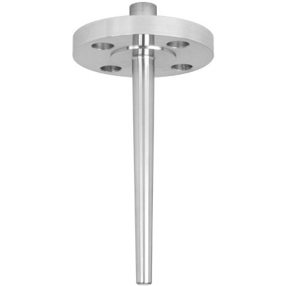
مغلف حراري مع شفة
الوصف
كل غلاف حراري/أنبوب حماية يُعد مكوّنًا مهمًا في أي نقطة قياس للحرارة. يُستخدم لفصل العملية عن المنطقة المحيطة، وبالتالي حماية البيئة وطاقم التشغيل، كما يمنع الوسطات العدوانية والضغوط المرتفعة ومعدلات التدفق من التأثير مباشرةً على مستشعر درجة الحرارة، وبذلك يتيح إمكانية استبدال الترمومتر أثناء التشغيل.
استنادًا إلى إمكانيات التطبيق شبه غير المحدودة، توجد أعداد كبيرة من النماذج، مثل تصاميم غلاف حراري/أنبوب حماية أو المواد. يُعد نوع وصلة العملية وطريقة التصنيع الأساسية من معايير التمييز التصميمية المهمة. ويمكن إجراء تمييز أساسي بين الأغلفة الحرارية/أنابيب الحماية الملولبة والملحومة، وتلك التي تحتوي على وصلات شفة.
المزايا
- تصميم للظروف القاسية
- طلاء للأحمال العملية المسببة للتآكل أو الانحلال
- أشكال ممكنة للجلبة الواقية: مخروطية، مستقيمة، متدرجة
الأسئلة والأجوبة
ما هو الغلاف الحراري TW10 ولأي غرض يُستخدم؟
هو غلاف حراري بشفة يُستخدم لحماية مستشعر درجة الحرارة من الوسطات العدوانية والضغوط العالية ومعدلات التدفق، ويسمح باستبدال الترمومتر دون إيقاف العملية.
في أي الصناعات يُستخدم طراز TW10؟
يُستخدم في صناعة البتروكيماويات، وتطبيقات البر/البحر (on-/offshore)، وأعمال إنشاء المصانع، خاصةً حيث توجد أحمال عمليات عالية أو متطلبات كيميائية قاسية.
ما هي مواد تصنيع الغلاف الحراري المتوفرة؟
تشمل الخيارات Stainless steel 304/304L وStainless steel 316/316L و1.4571 و1.4404 وA105 وAlloy C4 وAlloy C276 وAlloy 400 وTitanium grade 2 وTantalum sheet.
ما هي أشكال الغلاف الحراري المتاحة؟
يمكن توريد الغلاف الحراري بأشكال مخروطية (tapered) أو مستقيمة (straight) أو متدرجة (stepped).
ما هي وصلات العملية المدعومة؟
تشمل الوصلات الشفوفة وفق ASME B16.5 وEN 1092-1 وDIN 2527، بالإضافة إلى اللولبية M20 x 1.5 و½ NPT female thread وG ½ female thread.
هل يناسب TW10 الوسطات التآكلية أو الكاشطة؟
نعم، يتوفر طلاء خاص للحالات ذات الأحمال العملية التآكلية أو الكاشطة، كما توفر خيارات مواد مثل Alloy C276 وTantalum sheet للمتطلبات الكيميائية العالية.
ما الذي يميز TW10 عن غيره من الأغلفة الحرارية؟
يتميز TW10 بتصميمه التحملّي الثقيل (heavy-duty) وبكونه مصنوعًا آليًا من قطعة واحدة (solid-machined) مع شفة، مما يجعله مناسبًا للأحمال العملية والكيميائية العالية.
اجمع TW10 لمهمتك
يُبنى رقم المادة تلقائيًا. عند الشك — تواصل مع مهندس؛ سنساعدك حسب معطيات الخط.
- خيارات اللحامFull penetration welded
- ستايل غلاف ترمومتر (Thermowell)Tapered
- وحدة القياسMetric (mm)
- حجم الشفةASME 1 inch
- تصنيف الضغطClass 150
- وجه الشفةRF (Raised face)
- التوصيل مع مقياس الحرارة [N]1/2 NPT female
- قطر فوهة التوصيل الداخلي / قطر فوهة الأنبوب (Intern. nozzle dia.)WIKA (Standard Germany)
- طول الإدخال [U]150
- طول الرأس [H]57
- مادة الفلنجةStainless steel 316/316L
- المادةStainless steel 316/316L
- قطر القضيب [Bd أو F2]30 mm
- قطر التجويف [B أو d1]—
- قطر الجذر [Q]22,0
- قطر الطرف [V أو F3]—
- الشهادات—
أكمل التهيئة
اختر جميع الخيارات لإرسال الطلب.
| الطراز | TW10 |
| السلسلة | TW |
| النوع الفرعي | Thermowell |
| وصلة العملية | ASME B16.5EN 1092-1DIN 2527M20 x 1.5½ NPT female threadG ½ female thread |
| مادة جراب الحرارة | Stainless steel 304/304L, Stainless steel 316/316L, Stainless steel 1.4571, Stainless steel 1.4404, A105, Alloy C4, Alloy C276, Alloy 400, Titanium grade 2, Tantalum sheet |
| جراب الحرارة | نعم |
| شكل جراب الحرارة | tapered, straight, stepped |
| لغات ورقة البيانات | EN |
| Basic information | |
|---|---|
| Thermowell form | ■ Tapered ■ Straight ■ Stepped ■ ScrutonWell design per SP 05.16 (selectable) |
| Versions | |
| DesignTW10-F | Full penetration weld version |
| DesignTW10-P | With double weld seam (weld seam strength 3 mm) |
| DesignTW10-R | With double weld seam (weld seam strength 6 mm) |
| DesignTW10-S | Screw-welded design, weld seam does not come into direct contact with the medium |
| DesignTW10-B | Screw-welded design, additional weld seam on the process side (sealing joint) |
| DesignTW10-W | Forged version without welded joint |
| Material (wetted) | ■ Stainless steel 304/304L ■ Stainless steel 316/316L ■ Stainless steel 1.4571 ■ Stainless steel 1.4404 ■ A105 ■ Alloy C4 ■ Alloy C276 ■ Alloy 400 ■ Titanium grade 2 1) ■ Tantalum sheet for wetted parts ■ Restricted choice of materials withTW10-W |
| Coating | |
| Hardfacing for abrasive process loads with Stellite ® 6 | ■ Laser cladding Layer thickness 1.6 mm[0.062 in] (standard) Higher layer thickness on request ■ Plasma Transfer Arc (PTA) Layer thickness 1.6 mm[0.062 in] (standard) up to 3.2 mm[0.125 in] ■ Air Plasma Spraying (APS) Layer thickness max. 1.6 mm[0.062 in] ■ High Velocity Oxide Fuel (HVOF) Layer thickness 0.5 mm[0.02 in] |
| Corrosion protection for high chemical loads | ■ PFA Layer thickness min. 0.4 mm[0.015 in] (standard) or min. 0.6 mm[0.024 in] (special design) ■ ECTFE (Halar ® ) Layer thickness min. 0.6 mm[0.024 in] → Other resistant coatings on request |
| Process connection | |
|---|---|
| Type of process connection | |
| Flange | ■ Per ASME B16.5 ■ Per EN 1092-1 ■ Per DIN 2527 → Other flanges on request |
| TW10-W | ■ Dimensions in accordance with ASME B16.5 ■ Dimensions in accordance with EN 1092-1 ■ Dimensions in accordance with DIN 2527 |
| Connection to thermometer N | ■ ½NPTfemale thread ■ G½female thread ■ M20 x 1.5 |
| Bore size B | ■ 6.2 mm[0.244 in] ■ 6.6 mm[0.260 in] ■ 7.0 mm[0.276 in] ■ 8.2 mm[0.323 in] ■ 8.5 mm[0.355 in] ■ 9.0 mm[0.354 in] ■ 9.8 mm[0.385 in] ■ 10.2 mm[0.402 in] ■ 12.2 mm[0.480 in] |
| Insertion length U | ■ 150 mm[5.9 in] ■ 200 mm[7.87 in] ■ 250 mm[9.84 in] ■ 300 mm[11.81 in] ■ 350 mm[13.78 in] ■ 400 mm[15.75 in] ■ 6 in [152 mm] ■ 7 in [178 mm] ■ 10 in [254 mm] ■ 13 in [330 mm] ■ 16 in [406 mm] |
| → Other insertion lengths on request | |
| Min. insertion length | Depending on the selected version |
| Max. insertion length 1) | 800 mm[31.5 in] |
| Connection length H | ■ 45 mm[1.77 in] ■ 57 mm[2.25 in] ■ 60 mm[2.36 in] ■ 83 mm[3.25 in] ■ 108 mm[4.25 in] ■ 133 mm[5.25 in] → Other connection lengths on request |
| Min. Connection length Max. Connection length | Depending on the selected version 250 mm[10 in] |
| Version | AARH in µinch | Ra in µm | Rz in µm | |
|---|---|---|---|---|
| Sealing face roughness | ||||
| ASME B16.5 | Stock finish | 125 ... 250 | 3.2 ... 6.3 | - |
| Smooth finish | < 125 | < 3.2 | - | |
| RTJ | < 63 | < 1.6 | - | |
| Tongue/groove | < 125 | < 3.2 | - | |
| EN 1092-1 | Form B1 | - | 3.2 ... 12.5 | 12.5 ... 50 |
| Form B2 | - | 0.8 ... 3.2 | 3.2 ... 12.5 | |
| DIN 2527 | Form C | - | - | 40 ... 160 |
| Form E | - | - | < 16 |
| Max. process temperature, process pressure | Depending on: ■ Thermowell design - Dimensions - Material - Coating - Flange pressure rating ■ Process conditions - Flow rate - Density of medium |
|---|---|
| Wake frequency calculation (option) | The calculation in accordance with ASME PTC 19.3 TW-2016 of individual thermowells minimises the risk of dynamic damage that can be caused by the vortex shedding of a Kármán vortex street (Vortex Induced Vibration; VIV). In addition, the static loads due to lateral flow and the process pressure are calculated depending on the temperature. The calculation can be carried out independently using an online tool or as aWIKA engineered service (subject to charges). → |
| For further information see Technical information IN 00.15 'Wake frequency calculation'. |
عرض الكل (8)
| DN | PN in lbs | Dimensions in mm[in] | Weight in kg [lbs] (approx.) | ||||
|---|---|---|---|---|---|---|---|
| H | Ø Q | ØV | U = 4" | U = 13" | U = 22" | ||
| 1" | 150 | approx. 57 [2 ¼] | 22 [0.875] | 16 [0.625] | 1.4 [3.086] | 1.9 [4.188] | 2.3 [5.070] |
| 300 | approx. 57 [2 ¼] | 22 [0.875] | 16 [0.625] | 2.1 [4.629] | 2.6 [5.732] | 3.0 [6.613] | |
| 600 | approx. 57 [2 ¼] | 22 [0.875] | 16 [0.625] | 2.3 [5.070] | 2.8 [6.172] | 3.2 [7.054] | |
| 1,500 | approx. 83 [3 ¼] | 22 [0.875] | 16 [0.625] | 4.3 [9.479] | 4.8 [10.582] | 5.2 [11.464] | |
| 2,500 | approx. 83 [3 ¼] | 22 [0.875] | 16 [0.625] | 5.6 [12.345] | 6.1 [13.448] | 6.5 [14.330] | |
| 1 ½" | 150 | approx. 57 [2 ¼] | 25 [1.000] | 19 [0.750] | 1.8 [3.968] | 2.4 [5.291] | 3.0 [6.613] |
| 300 | approx. 57 [2 ¼] | 25 [1.000] | 19 [0.750] | 3.3 [7.275] | 3.9 [8.598] | 4.5 [9.920] | |
| 600 | approx. 57 [2 ¼] | 25 [1.000] | 19 [0.750] | 4.0 [8.818] | 4.7 [10.361] | 5.3 [11.684] | |
| 1,500 | approx. 83 [3 ¼] | 25 [1.000] | 19 [0.750] | 6.4 [14.109] | 7.1 [15.652] | 7.7 [16.975] | |
| 2,500 | approx. 83 [3 ¼] | 25 [1.000] | 19 [0.750] | 12.0 [26.455] | 12.6 [27.778] | 13.3 [29.321] | |
| 2" | 150 | approx. 57 [2 ¼] | 25 [1.000] | 19 [0.750] | 2.5 [5.511] | 3.1 [6.834] | 3.7 [8.157] |
| 300 | approx. 57 [2 ¼] | 25 [1.000] | 19 [0.750] | 3.7 [8.157] | 4.3 [9.479] | 4.9 [10.802] | |
| 600 | approx. 57 [2 ¼] | 25 [1.000] | 19 [0.750] | 4.2 [9.259] | 4.9 [10.802] | 5.5 [12.125] | |
| 1,500 | approx. 83 [3 ¼] | 25 [1.000] | 19 [0.750] | 11.0 [24.250] | 11.6 [25.573] | 12.3 [27.116] | |
| 2,500 | approx. 108 [4 ¼] | 25 [1.000] | 19 [0.750] | 17.0 [37.478] | 17.6 [38.801] | 18.3 [40.344] |
| DN | PN in bar | Dimensions in mm[in] | Weight in kg [lbs] (approx.) | |||
|---|---|---|---|---|---|---|
| H | Ø Q | ØV | U = 160mm | U = 500mm | ||
| 25 | 40 | 45 [1.771] | 22 [0.875] | 16 [0.625] | 1.9 [4.188] | 2.6 [5.732] |
| 63/64 | 45 [1.771] | 22 [0.875] | 16 [0.625] | 3.2 [7.054] | 3.9 [8.598] | |
| 100 | 45 [1.771] | 22 [0.875] | 16 [0.625] | 3.2 [7.054] | 3.9 [8.598] | |
| 40 | 40 | 45 [1.771] | 25 [1.000] | 19 [0.750] | 3.1 [6.834] | 4.0 [8.818] |
| 63/64 | 45 [1.771] | 25 [1.000] | 19 [0.750] | 4.8 [10.582] | 5.7 [12.566] | |
| 100 | 45 [1.771] | 25 [1.000] | 19 [0.750] | 4.8 [10.582] | 5.7 [12.566] | |
| 50 | 40 | 45 [1.771] | 25 [1.000] | 19 [0.750] | 3.9 [8.598] | 4.8 [10.582] |
| 63/64 | 45 [1.771] | 25 [1.000] | 19 [0.750] | 5.2 [11.464] | 6.1 [13.448] | |
| 100 | 45 [1.771] | 25 [1.000] | 19 [0.750] | 6.6 [14.550] | 7.5 [16.534] | |
| 80 | 40 | 60 [2.362] | 25 [1.000] | 19 [0.750] | 6.6 [14.550] | 7.5 [16.534] |
| 63/64 | 60 [2.362] | 25 [1.000] | 19 [0.750] | 7.6 [16.755] | 8.5 [18.739] | |
| 100 | 60 [2.362] | 25 [1.000] | 19 [0.750] | 10.2 [22.487] | 11.1 [24.471] | |
| 100 | 40 | 60 [2.362] | 25 [1.000] | 19 [0.750] | 8.3 [18.298] | 9.2 [20.282] |
| 63/64 | 60 [2.362] | 25 [1.000] | 19 [0.750] | 10.9 [24.030] | 11.8 [26.014] | |
| 100 | 60 [2.362] | 25 [1.000] | 19 [0.750] | 15.0 [33.069] | 15.9 [35.053] |
| TW10 | Thermowell with flange |
|---|---|
| TW15/TW50 | Threaded thermowell |
| TW20 | Weld-in thermowell (for welding socket) |
| TW25 | Weld-in thermowell (variable welding diameter) |
| TW30 | Thermowell in Vanstone design for lap flanges |
| Dimensions in mm[in] Surface texture z y x Tol. ISO 2768 - mK 0,5 ...6 >6 >30 >120 ...30 ...120 ...400 Check indicator language nominal size | Root diam- eter mm [inch] units SIZE ISO 14405 8015 Nur zur DR comments | Tip diam- eter www.wika.com D-63911 Klingenberg ALEXANDER WIEGAND SE & Co. KG Information sheets 1 / 1 | Strake height | Strake depth | Scruton length 1) | Insertion length 1) |
|---|---|---|---|---|---|---|
| - 63 16 4 1 ± 0,1 ± 0,2 ± 0,3 ± 0,5 GER/ENG | Ø Q ISO | ØV DEKLI1_EN_A4M_T01 26.04.2023 | Sh | Sw | SL | U |
| 1" pipe schedule 5 ... 80 | 24 [0.945] | 17 [0.669] | 2.5 [0.098] | 2.5 [0.098] | Max. 800 [31.5] | Max. 1,000 [39] |
| 1 ½" pipe schedule 5 ... 160 | 30 [1.181] | 20 [0.787] | 2.5 [0.098] | 2.5 [0.098] | Max. 800 [31.5] | Max. 1,000 [39] |
| 2" pipe schedule 5 ... 160 | 30 [1.181] | 20 [0.787] | 2.5 [0.098] | 2.5 [0.098] | Max. 800 [31.5] | Max. 1,000 [39] |
لم تجد الإجابة في الوثائق؟ سيرد المهندس خلال يوم عمل.
اسأل المهندس →26 مادة قياسية من عائلة TW
إذا كنت تعرف الرمز — اختر مباشرة. إذا لا — استخدم المُهيِّئ في الوضع «01».