
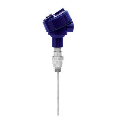
ترمومتر مقاومة
الوصف
يمكن دمج موازين الحرارة المقاومة في هذه السلسلة مع عدد كبير من تصاميم غلافات الحماية (thermowell). يُسمح بالاستخدام دون غلاف حماية عند استخدام وصلة ثابتة (ملحومة).
تتوفر مجموعة واسعة من التركيبات الممكنة للمستشعر ورأس التوصيل وطول الإدخال وطول الرقبة والتوصيل بغلاف الحماية (thermowell) وما إلى ذلك بالنسبة لموازين الحرارة؛ وهي مناسبة تقريبًا لأي بُعد لغلاف الحماية.
يمكننا، بشكل اختياري، تركيب مرسلات من نطاق WIKA داخل رأس التوصيل الخاص بـ TR10-0.
للموافقات الإضافية، راجع الصفحة 11
ميزان حرارة مقاومة، تجميع صناعي، الطراز TR10-0
المزايا
- مدى المستشعر من -196 ... +600 °C [-321 ... +1,112 °F]
- يمكن تركيب حساس RTD داخل غلاف واقٍ أو مباشرة في العملية باستخدام وصلة ثابتة أو زنبركية أو ضاغطة
- يمكن تجهيز المجموعات بمحوّلات أو بدونها لتحويل إشارة المقاومة إلى مخرج تناظري أو رقمي
- تمتلك المجموعة موافقات كهربائية للمواقع الخطرة المضادة للانفجار، وللحماية من دخول المواد، وللأغراض العامة.
- تشمل الجهات الكهربائية التي سجلت هذه الاعتمادات CSA وFM وIECEx وATEX. يمكن أن تكون الاعتمادات مع غلاف حراري ملحق أو بدونه، ويُشترط مسار اللهب المتكامل عند التوريد بدون غلاف حراري
- الحساس RTD مزود بزنبرك يضمن تلامساً محكماً مع قاعدة الغلاف الواقي (قابل للاستبدال)
الأسئلة والأجوبة
ما هو نطاق القياس لهذا الترمومتر؟
نطاق المستشعر من -196 … +600 °C [-321 ... +1,112 °F]، ونطاق درجة حرارة العملية من -196 … +600 °C.
ما نوع المستشعر وفئته؟
المستشعر من نوع Pt100 ومتوفر بفئات الدقة A وB وAA.
هل يمكن استخدامه في المناطق الخطرة؟
نعم، يحمل الموافقات ATEX وIECEx وFM وCSA وEAC وINMETRO وCCC وEx Ukraine، مثل ATEX: Ex ia IIC T1...T6 Ga/Gb وEx db IIC T6...T4 Gb. وعند التوريد بدون غلاف حماية حرارية يُشترط مسار اللهب المتكامل.
كيف يتم التثبيت في العملية؟
يمكن تركيب المستشعر داخل غلاف حماية حرارية أو مباشرة في العملية باستخدام وصلة ثابتة أو بنابض أو ضاغطة (compression fitting).
ما هي وصلات العملية المتاحة؟
½ NPT، ¾ NPT، G ½ B، G ¾ B، وأقطاب مترية M14 x 1.5 إلى M24 x 1.5.
ما هي إشارة الخرج المتوفرة؟
يمكن توفير التجميع مع مرسل يوفر خرج 4-20 mA مع دعم HART، أو بدون مرسل كإشارة مقاومة مباشرة.
هل يدعم المنتج تطبيقات السلامة الوظيفية؟
نعم، مصنف SIL 2 وفق IEC 61508 / IEC 61511.
ما الذي يميز TR10-0 عن الطرز المجاورة؟
TR10-0 هو تجميع صناعي قابل للتخصيص: خيارات التثبيت (بنابض/ثابت)، رؤوس توصيل مختلفة، مرسلات اختيارية، وتوافق مع عدد كبير من تصاميم أغلفة الحماية الحرارية، مع مستشعر بنابض قابل للاستبدال يضمن التلامس مع قاعدة الغلاف. ---
| الطراز | TR10-0 |
| السلسلة | TR10 |
| النوع الفرعي | Resistance thermometer |
| نطاق درجة الحرارة | −196…+600 °C · −50…+500 °C · −30…+300 °C · +0…+150 °C · −100…+450 °C · −50…+250 °C |
| مستوى السلامة الوظيفية (SIL) | SIL 2 (IEC 61508 / IEC 61511) |
| وصلة العملية | ½ NPT¾ NPTG ½ BG ¾ BM14 x 1.5M18 x 1.5M20 x 1.5M24 x 1.51/2NPT3/4NPT |
| درجة حرارة العملية | −196…+600 °C |
| إشارة الخرج | HART · 4-20 mA |
| وصلة كهربائية | M20 x 1.5, ½ NPT, ¾ NPT, M24 x 1.5 |
| مادة المجس | 1.4571, 316, Stainless steel |
| مادة جراب الحرارة | 1.4571, 316 |
| حرارة المحيط | −40…+80 °C |
| تصنيف IP | IP65 |
| الشهادات | CERoHSEACCCCREACHNACEATEXIECExFMCSAEx UkraineINMETRO |
| حماية الانفجار | Ex ia IIC T1...T6 GaATEX: Ex ia IIC T1...T6 Ga/Gb, Ex db IIC T6...T4 Gb, Ex eb IIC T1...T6 Gb, Ex nA IIC T1...T6 GcIECEx: Ex ia IIC T1...T6 Ga/Gb, Ex db IIC T6...T4 Gb, Ex eb IIC T1...T6 Gb, Ex nA IIC T1...T6 GcFM: Class I, Div 1, Groups B, C, D, T6; Class II/III, Div 1, Groups E, F, GCSA: Class I, Div 1, Groups B, C, D, T6; Class II/III, Div 1, Groups E, F, GEAC: 0Ex ia IIC T6...T1 Ga, 1Ex d IIC T6...T4 GbEx Ukraine: II 1G Ex ia IIC T1...T6 GaINMETRO: II 1G Ex ia IIC T1...T6 GaCCC: Ex ia IIC T1~T6 Ga/Gb, Ex d IIC T4~T6 GbEx i (gas) Zone 0, 1, 2Ex i (dust) Zone 20, 21, 22Ex d (gas) Zone 1, 2Ex d (dust) Zone 21Ex e (gas) Zone 1, 2Ex n (gas) Zone 2Class I, Division 1, Groups B, C, D, T6Ex d IIB+H2 T4~T6 GbEx d IIC T4~T6 GbEx ia IIC T125...T65 °C DaEx db IIB + H2 T6...T4 GbEx db IIC T6...T4 GbEx eb IIC T1...T6 Gb(3)Ex nA IIC T1...T6 Gc XClass I, division 1, group B, C, D, T6 type 4/XClass II or III, division 1, group E, F, G type 4/XEx d IBC Gb T6/T5/T4Ex ia IIC T6...T1 Ga XEx d IIC T6...T4 Gb XEx nA IIC T6...T1 Gc X |
| نوع المستشعر | Pt100 |
| فئة المستشعر | A, B, AA |
| قطر المجس | 3 mm |
| جراب الحرارة | نعم |
| شكل جراب الحرارة | fabricated |
| لغات ورقة البيانات | EN, DE |
| Approval | Explosion protection | |||||
|---|---|---|---|---|---|---|
| Ex i (gas) Zone 0, 1, 2 | Ex i (dust) Zone 20, 21, 22 | Ex d (gas) Zone 1, 2 | Ex d (dust) Zone 21 | Ex e (gas) Zone 1, 2 | Ex n (gas) Zone 2 | |
| ATEX | x | x | x | x | x | x |
| IECEx | x | x | x | x | x | x |
| FM | - | - | x | x | - | - |
| CSA | - | - | x | x | - | - |
| EAC | x | x | x | x | - | x |
| Ex Ukraine | x | x | x | x | - | - |
| INMETRO | x | x | - | - | - | - |
| CCC | x | x | x | x | x | x |
| Model | Material | Cable entry thread size | Ingress protection (max.) 1) IEC/EN 60529 | Cap | Surface | Connection to neck tube | |
|---|---|---|---|---|---|---|---|
| BS | Aluminium | ■ M20 x 1.5 ■ ½NPT | IP65 2) | Flat cover with 2 screws | Blue, painted (RAL 5022) | M24 x 1.5 | |
| BSZ, BSZ-K BSZ | BSZ-H, Aluminium | BSZ-HK ■ M20 x 1.5 ■ ½NPT | BSS BSS-H IP65 2) | BVS BVS (NuG) Spherical hinged cover with cylinder head screw | Blue, painted (RAL 5022) | 1/4000 M24 x 1.5 | |
| BSZ-H, BSZ-H | BSZ-HK Aluminium | BSS ■ M20 x 1.5 ■ ½NPT | BVS BSS-H IP65 2) | BVS (NuG) 1/4000 Raised hinged cover with cylinder head screw | Blue, painted (RAL 5022) | 7/8000 5/6000 M24 x 1.5 |
| Model | Explosion protection | ||||||
|---|---|---|---|---|---|---|---|
| Without | Ex i (gas) Zone 0, 1, 2 | Ex i (dust) Zone 20, 21, 22 | Ex d (gas) Zone 1, 2 | Ex d (dust) Zone 21 | Ex e (gas) Zone 1, 2 | Ex nA (gas) Zone 2 | |
| BS | x | x | x | - | - | - | - |
| BSZ | x | x | x | - | - | x 3) | x 4) |
| BSZ-H | x | x | x | - | - | x 3) | x 4) |
| Model | Material | Cable entry thread size | Ingress protection (max.) 1) IEC/EN 60529 | Cap | Surface | Connection to neck tube | |
|---|---|---|---|---|---|---|---|
| KN4-A | Aluminium | ■ ½NPT ■ M20 x 1.5 | IP65 3) | Screw-on lid | Blue, painted (RAL 5022) | ■ M24 x 1.5 ■ ½NPT | |
| KN4-P 2) | Polypropylene | ½NPT | IP65 3) | Screw-on lid | White | ½NPT | |
| BVC 1/4000 F | Aluminium | ■ ½NPT ■ ¾NPT ■ M20 x 1.5 | IP66 3) | Screw cap | Blue, painted (RAL 5022) | ½NPT | |
| 5/6000 1/4000 S | 7/8000 Stainless steel | 7/8000 DIH50 ■ ½NPT ■ ¾NPT ■ M20 x 1.5 | KN4-P Anschlussgehäuse IP66 3) | BVC Screw cap | Natural finish | ½NPT | |
| 7/8000W | Aluminium | ■ ½NPT ■ ¾NPT ■ M20 x 1.5 | IP66 3) | Screw cap | Blue, painted (RAL 5022) | ½NPT | |
| 7/8000 DIH50 7/8000 S | andere Anschlussgehäuse Stainless steel | KN4-P ■ ½NPT ■ ¾NPT ■ M20 x 1.5 | BVC IP66 3) | Screw cap | Natural finish | ½NPT | |
| 7/8000W/ DIH50 4) | Aluminium | ■ ½NPT ■ ¾NPT ■ M20 x 1.5 | IP66 3) | Screw-on lid | Blue, painted (RAL 5022) | ½NPT | |
| andere Anschlussgehäuse 7/8000 S / DIH50 4) | KN4-P Stainless steel | BVC ■ ½NPT ■ ¾NPT ■ M20 x 1.5 | IP66 3) | Screw-on lid | Natural finish | ½NPT |
عرض الكل (20)
| Model | Explosion protection | ||||||
|---|---|---|---|---|---|---|---|
| Without | Ex i (gas) Zone 0, 1, 2 | Ex i (dust) Zone 20, 21, 22 | Ex d (gas) Zone 1, 2 | Ex d (dust) Zone 21 | Ex e (gas) Zone 1, 2 | Ex nA (gas) Zone 2 | |
| KN4-A | x | x | - | - | - | - | - |
| KN4-P 2) | x | - | - | - | - | - | - |
| 1/4000 F | x | x | x | x | x | x | x |
| 1/4000 S | x | x | x | x | x | x | x |
| 7/8000W | x | x | x | x | x | x | x |
| 7/8000 S | x | x | x | x | x | x | x |
| 7/8000W/ DIH50 4) | x | x | x | x | - | - | - |
| 7/8000 S / DIH50 4) | x | x | x | x | - | - | - |
| Versions | Vibration-resistant, sheathed measuring cable (MI cable) | |
|---|---|---|
| Optimal heat transfer | Requirement | ■ Correct measuring insert length ■ Correct measuring insert diameter |
| Bore diameter of the thermowell | Max. 1 mm[0.04 in] larger than measuring insert diameter | |
| Joint width | For joint width > 0.5 mm[> 0.02 in] between thermowell and measuring insert: →Negative impact on heat transfer →Unfavourable response behaviour of the thermometer | |
| Measuring insert diameter Ø d | ■ 3.0mm ■ 6.0mm ■ 8.0mm ■ 1/8 in or 0.125 in [3.17 mm] ■ 3/16 in or 0.188 in [4.75 mm] ■ 1/4 in or 0.250 in [6.35 mm] | |
| Other measuring insert diameters on request | ||
| Insertion length | When fitting the measuring insert into a thermowell, it is very important to determine the correct insertion length (= thermowell length for bottom thicknesses of ≤ 5.5 mm[≤ 0.22 in]). In order to ensure that the measuring insert is firmly pressed down onto the bottom of the thermowell, the insert must be spring-loaded (spring travel: 0 ... 10 mm[0 ... 0.39 in]). | |
| Spring travel | ||
| Spring-loaded plate | Max. 10 mm[0.39 in] | |
| Self gripping spring | Max. 20 mm[0.79 in] |
| Transmitter models | Model T15 | Model T32 |
|---|---|---|
| Transmitter data sheet | TE 15.01 | TE 32.04 |
| Figure | ||
| Output | ||
| 4 ...20mA | x | x |
| HART ® protocol | - | x |
| Connection method | ■ 1 x 2-wire ■ 1 x 3-wire ■ 1 x 4-wire | ■ 1 x 2-wire ■ 1 x 3-wire ■ 1 x 4-wire ■ 2 x 2-wire |
| Measuring current | < 0.2mA | < 0.3mA |
| Explosion protection | Option | Option |
| Possible mounting positions for transmitters | Model T15 | Model T32 |
|---|---|---|
| BS | ○ | - |
| BSZ | ○ | ○ |
| BSZ-H | ● | ● |
| KN4-A | ○ | ○ |
| 1/4000 | ○ | ○ |
| 1/4000 with DIH50 | ○ | ○ |
| 7/8000 | ○ | ○ |
| 7/8000 with DIH50 | ○ | ○ |
| Neck tube design | Diameter | Connection to head | Connection to thermowell | Material |
|---|---|---|---|---|
| Neck tube with counter nut to head | 14 x 2.5mm [0.55 x 0.09 in] | M20 x 1.5 (with counter nut) | Mounting thread | 1.4571 |
| Double threaded hex bushing (with hexagonal spanner flats) | - | M24 x 1.5,½NPT | Mounting thread | 1.4571 |
| 'Nipple-union-nipple' neck tube | ~ 22 mm[0.87 in] | ½NPT | Mounting thread | 316 |
| ~ 27 mm[1.06 in] | ¾NPT | Mounting thread | 316 | |
| Double threaded hex bushing (tube section) | ~ 22 mm[0.87 in] | ½NPT | Mounting thread | 316 |
| ~ 27 mm[1.06 in] | ¾NPT | Mounting thread | 316 |
| Neck tube design | Diameter | Thread to the thermowell |
|---|---|---|
| Neck tube with counter nut to head | 14 x 2.5mm [0.55 x 0.09 in] | ■ ½NPT ■ ¾NPT ■ G½B ■ G¾B ■ G¼B ■ M14 x 1.5 ■ M18 x 1.5 ■ M20 x 1.5 |
| Double threaded hex bushing (with hexagonal spanner flats) | - | ■ G½B ■ G¾B ■ G¼B ■ ½NPT ■ ¾NPT ■ M14 x 1.5 ■ M18 x 1.5 ■ M20 x 1.5 |
| 'Nipple-union-nipple' neck tube | ~ 22 mm[0.87 in] | ½NPT |
| ~ 27 mm[1,06 in] | ¾NPT | |
| Double threaded hex bushing (tube section) | ~ 22 mm[0.87 in] | ½NPT |
| ~ 27 mm[1,06 in] | ¾NPT |
| Neck tube design | Neck length | Min. / Max. neck length |
|---|---|---|
| Neck tube with counter nut to head | 150 mm[approx. 6 in] | 75 mm[approx. 3 in] / 250 mm[approx. 10 in] |
| Double threaded hex bushing (with hexagonal spanner flats) | ||
| M24 x 1.5 to connection head, parallel thread to thermowell | 13 mm[0.51 in] | - |
| 1/2 NPT to connection head, parallel thread to thermowell | 25 mm[0.98 in] | - |
| M24 x 1.5 to connection head, tapered thread to thermowell | 25 mm[0.98 in] | - |
| 1/2 NPT to connection head, tapered thread to thermowell | 25 mm[0.98 in] | - |
| 'Nipple-union-nipple' neck tube | 150 mm[approx. 6 in] | 75 mm[approx. 3 in] / 250 mm[approx. 10 in] |
| Double threaded hex bushing (tube section) | 50 mm[approx. 2 in] | 50 mm[approx. 2 in] / 250 mm[approx. 10 in] |
| Ambient and storage temperature | -40 ...+80 °C [-40 ...+176 °F] |
|---|---|
| Vibration resistance | The information on vibration resistance refers to the tip of the measuring insert. →For detailed specifications on the vibration resistance of Pt100 sensors, see Technical information IN 00.17 at www.wika.de. |
| Standard | 6 g peak-to-peak, wire-wound measuring resistor or thin film |
| Option | ■ Vibration-resistant probe tip, max. 20 g peak-to-peak, thin-film measuring resistor ■ Highly vibration-resistant probe tip, max. 50 g peak-to-peak, thin-film measuring resistor |
| First index number | Degree of protection / Short description | Test parameters |
|---|---|---|
| Degrees of protection against solid foreign bodies (defined by the 1st index number) | ||
| 5 | Dust-protected | Per IEC/EN 60529 |
| 6 | Dust-tight | Per IEC/EN 60529 |
| Degrees of protection against water (defined by the 2nd index number) | ||
| 4 | Protected against splash water | Per IEC/EN 60529 |
| 5 | Protected against water jets | Per IEC/EN 60529 |
| 6 | Protected against strong water jets | Per IEC/EN 60529 |
| 7 1) | Protected against the effects of temporary immersion in water | Per IEC/EN 60529 |
| 8 1) | Protected against the effects of permanent immersion in water | As agreed upon |
| Model | Data sheet | Illustration |
|---|---|---|
| TW10 | TW95.10 | |
| TW15 | TW95.15 | |
| TW20 | TW95.20 | |
| TW25 | TW95.25 | |
| TW30 | TW95.30 | |
| TW31 | TW95.31 | |
| TW50 | TW95.50 | |
| TW55 | TW95.55 |
| Logo | Description | Country |
|---|---|---|
| EU declaration of conformity | European Union |
| Logo | Description | Country | |
|---|---|---|---|
| EU declaration of conformity ATEX directive | European Union | ||
| Zone 22 dust II 3D Ex tc IIICTX °C Dc X IECEx - in combination with ATEX Hazardous areas | International | ||
| - Ex n 2) Zone 2 gas Ex nA IIC T1 ...T6 Gc X Zone 22 dust Ex tc IIICTX °C Dc X FM Hazardous areas - Ex d (XP) Division 1 gas Class I, division 1, group B, C, D, T6 type 4/4X Division 1 dust Class II or III, division 1, group E, F, Gtype 4/4X | |||
| CSA | USA and Canada | ||
| Safety (e.g. electr. safety, overpressure, ...) Hazardous areas - Ex d (XP) | Class I, division 1, groups B, C, D, T6 type 4/4X | USA and Canada |
| Logo | Description | Country |
|---|---|---|
| EAC (option) Hazardous areas | Eurasian Economic Community | |
| - Ex n Zone 2 gas 2Ex nA IIC T6 ...T1 Gc X Ex Ukraine Hazardous areas - Ex i Zone 0 gas II 1G Ex ia IIC T1 ...T6 Ga Zone 1 mounting to zone 0 gas II 1/2G Ex ia IIC T1 ...T6 Ga/Gb | Ukraine | |
| Zone 21 dust II 2D Ex tb IIIC T85 °C Db INMETRO Hazardous areas - Ex i Zone 0 gas II 1G Ex ia IIC T1 ...T6 Ga Zone 1 mounting to zone 0 gas II 1/2G Ex ia IIC T1 ...T6 Ga/Gb Zone 20 dust Ex ia IIIC T125 ...T65 °C Da Zone 21 mounting to zone 20 dust Ex ia IIIC T125 ...T65 °C Da/Db 3) | Brazil | |
| CCC Hazardous areas - Ex i Zone 0 gas Ex ia IIC T1 ~ T6 Ga Zone 1 gas Ex ia IIC T1 ~ T6 Gb Zone 1 mounting to zone 0 gas Ex ia IIC T1 ~ T6 Ga/Gb Zone 2 gas Ex ic IIC T1 ~ T6 Gc Zone 21 dust Ex iaD 21 T65/T95/T125°C - Ex d Zone 1 gas Ex d IIB+H2 T4~T6 Gb Zone 1 gas Ex d IIC T4~T6 Gb | China | |
| PAC Russia Metrology, measurement technology | Russia | |
| PAC Kazakhstan | Kazakhstan | |
| - | Metrology, measurement technology MChS | Kazakhstan |
| PAC Belarus Metrology, measurement technology | Belarus | |
| - | PAC Ukraine Metrology, measurement technology | Ukraine |
| PAC Uzbekistan | ||
| Metrology, measurement technology | Uzbekistan |
| Certification type | Measurement accuracy | Material certificate |
|---|---|---|
| 2.2 test report | x | x |
| 3.1 inspection certificate | x | x |
| DAkkS calibration certificate | x | - |
| Model | Description D |
|---|---|
| PIH-L | Connection head with flat screw-on lid |
| PIH-H | Connection head with high screw-on lid |
| PIH-W | Connection head with high screw-on lid and window |
| PIR-L | Connection head with flat screw-on lid, pipe or wall mounting |
| PIR-H | Connection head with high screw-on lid, pipe or wall mounting |
| PIR-W | Connection head with high screw-on lid and window, pipe or wall mounting E |
| Materials | ||
|---|---|---|
| Lower part of the case PIX-X Explosion CONNECTION HEAD | Aluminium die-casting EN AC-43500 AlSi10MnMg / AA 365.0; copper content ≤ 0,05% (low copper) drawing number 14654707.01 | |
| Screw-on lid scale 1:1 | Aluminium die-casting EN AC-43500 AlSi10MnMg / AA 365.0; copper content ≤ 0,05% (low copper) F reference DR 08 sheets 1 / 1 | |
| Window Check indicator size | Glass ALEXANDER WIEGAND SE & Co. KG comments | |
| Sealing language | ■ EPDM -60 ...+90 °C [-76 ... 194 °F] ■ MVQ-60 ...+110°C [-76 ... 230 °F], on request ■ FKM -20 ...+110°C [-4 ... 230 °F], on request www.wika.com D-63911 Klingenberg DEKLI1_EN_A4M_T00 26.04.2023 [inch] | |
| Case surface | ||
| Colour | Lower body | WIKA product grey RAL 7035 |
| Screw-on lid | WIKA product blue RAL 5022 | |
| Coating | ■ PE/PU (polyester/polyurethane) powder coating ■ 90 ±40 µm thickness ■ Electrically conductive per IEC 60243-1:2013 ■ The painted test objects / surfaces were subjected to a salt mist and condensation test per C5-M, per ISO 12944-6.The evaluation per ISO 4624, ISO 4628-2/-3/- 4/-5/-6, as well as the scored areas per ISO 12994 A.2 showed no significant abnormalities. ■ Cross-cut:GT 0 (...1) per ISO 2409:2013 - 1c or 2a |
لم تجد الإجابة في الوثائق؟ سيرد المهندس خلال يوم عمل.
اسأل المهندس →