
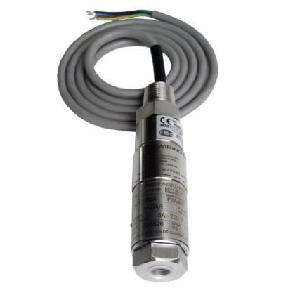
مفتاح ضغط مصغّر، غلاف مقاوم للهب Ex d
الوصف
تم تطوير مفاتيح الضغط الميكانيكية عالية الجودة هذه خصيصًا لتطبيقات تتطلب السلامة بدرجة حرجة. تتمثل الميزة الكبيرة لمفاتيح الضغط الميكانيكية في أنه لا يلزم وجود جهد إمداد لعملية التبديل.
أثناء الإنتاج، يتم تتبّع المفاتيح بواسطة برنامج ضمان الجودة في كل خطوة، ثم يتم اختبارها بنسبة 100 %. وبفضل إحكامها/تصميمها المدمج، يمكن تركيب مفتاح الضغط طراز PXA في بيئات القياس ذات المساحة المحدودة. يمكن لهيكل/غلاف المفتاح المتين المصنوع من الفولاذ المقاوم للصدأ 316 أن يتحمل ظروف التشغيل القاسية والمسببة للتآكل في صناعة العمليات، ضمن مجالات عمل تصل إلى 1,000 bar.
المزايا
- تصميم مدمج ونحيف
- هيكل مفتاح متين من الفولاذ المقاوم للصدأ 316، IP66، NEMA 4X
- تشكيلة واسعة من مجالات الضبط المتاحة، 1 … 2.5 bar إلى 200 … 1,000 bar
- تكرارية نقطة الضبط ≤ 1 % للتبديل الموثوق
- قدرة تبديل عالية وتشكيلة واسعة من متغيرات التلامس والتوصيلات الكهربائية
الأسئلة والأجوبة
ما هي نطاقات الضبط المتاحة لمفتاح الضغط PXA؟
يتوفر تشكيلة واسعة من نطاقات الضبط من 1 … 2.5 bar حتى 200 … 1,000 bar، إضافة إلى نطاق تفريغ/ضغط -1 … 1.5 bar ونطاق 1.6 … 6.0 bar.
ما دقة التبديل لهذا المفتاح؟
تكرارية نقطة الضبط ≤ 1 % من نهاية نطاق الضبط، وفقًا للمعيار IEC 61298-2:2008.
ما هي وصلات العملية المتاحة؟
الوصلة الأساسية ¼ NPT أنثى، مع بدائل عبر محوّلات: ½ NPT أنثى أو ذكر، G ¼ A ذكر، وG ½ A ذكر.
هل يناسب PXA الوسائط العدوانية؟
نعم، فهو مصمم للوسائط الغازية والسائلة العدوانية وعالية اللزوجة أو الملوثة، وتكون الأجزاء المبللة من Hastelloy C276 أو Stainless steel 316L، مع إحكامات من FPM أو NBR أو EPDM.
ما حدود درجات الحرارة المسموحة؟
درجة حرارة البيئة المحيطة من -50 … +85 °C، ودرجة حرارة العملية من -40 … +200 °C.
ما هو تصنيف الحماية من الانفجار والحماية من دخول الأجسام؟
الغلاف مقاوم للهب Ex d بشهادات ATEX (II 1/2 GD، II 2 GD) وIECEx (Ex d IIC T6/T4 وغيرها)، وتصنيف الحماية IP66 (وNEMA 4X).
هل يدعم PXA تطبيقات السلامة الوظيفية؟
نعم، يتوفر خيار SIL 3-capable وفق IEC 61508 / IEC 61513، كما يحمل شهادات NACE MR0175 / ISO 15156 وNACE MR0103 / ISO 17945 للخدمات الحمضية.
ما الذي يميّز PXA عن مفاتيح الضغط الأخرى؟
هو مفتاح ميكانيكي مصغّر لا يحتاج جهد إمداد للتبديل، بهيكل مدمج من Stainless steel 316 مناسب لنقاط القياس ذات المساحة المحدودة مثل لوحات التحكم، مع نطاقات ضغط تصل إلى 1,000 bar وحماية Ex d.
| الطراز | PXA |
| السلسلة | Process Mini Series |
| النوع الفرعي | Mechanical pressure switch |
| نطاق الضغط | 1…2.5 bar · 2…6 bar · 3…10 bar · 6…25 bar · 14…60 bar · 25…100 bar · 50…160 bar · 70…400 bar · 150…700 bar · 200…1000 bar · -1…1.5 bar · 1.6…6 bar |
| فئة الدقة | ≤ 1 % of end of setting range (set point repeatability) |
| معيار الدقة | IEC 61298-2:2008 |
| مستوى السلامة الوظيفية (SIL) | SIL 3-capable (option), per IEC 61508 / IEC 61513 |
| وصلة العملية | ¼ NPT, female thread½ NPT, female thread via adapter½ NPT, male thread via adapterG ¼, female thread via adapterG ½ A, male thread via adapterG ¼ A, male thread via adapter1/4 NPT, female thread1/2 NPT, female thread via adapter1/2 NPT, male thread via adapterG1/4, female thread via adapterG1/2 A, male thread via adapterG1/4 A, male thread via adapter |
| درجة حرارة العملية | −40…+200 °C |
| وصلة كهربائية | Threaded connection with connection cable (½ NPT male, M20 x 1.5, ½ NPT female, ¾ NPT female), terminal box with 3 x ½ NPT female, IP65 |
| وظيفة التبديل | Adjustable set point with fixed dead band, switching direction (rising/falling) configurable |
| نقاط التبديل | 1 |
| مادة العلبة | Stainless steel 316 |
| مادة الأجزاء الملامسة | Hastelloy C276, Stainless steel 316L |
| مادة الإحكام | FPM, NBR, EPDM |
| حرارة المحيط | −50…+85 °C |
| تصنيف IP | IP66 |
| الوزن | 0.6 kg |
| الشهادات | CERoHSEACNACENACE MR0175 / ISO 15156NACE MR0103 / ISO 17945 |
| حماية الانفجار | Ex d I MbATEX: II 1/2 GD, II 2 GDIECEx: Ex d IIC T6/T4, Ex ta/tb IIIC T85°C/T135°C IP66, Ex d IIC T85°C/T135°C Gb, Ex tb IIIC T85°C/T135°C IP66 DbEACEx UkraineCCCKOSHAII 1/2 GDII 2 GD (version with sensor element 'P')Ex d IIC T6/T4 Ga/GbEx ta/tb IIIC T85°C/T135°C IP66 Da/DbEx d IIC T85°C/T135°C GbEx tb IIIC T85°C/T135°C IP66 Db (version with sensor element 'P')Ex d IIC T6/T5 GbEx tb IIIC T85/T135 Db IP66ATEXIECEx |
| لغات ورقة البيانات | EN |
| Version | Miniature pressure switch, flameproof enclosure Ex d |
|---|---|
| Special design feature | ■ For oxygen, oil- and grease-free ■ Per NACE 1) MR0175 / ISO 15156, use in H₂S-containing environments in oil and gas production ■ Per NACE 1) MR0103 / ISO 17945, metals resistant to sulphide stress cracking ■ Drying of wetted parts ■ Offshore version ■ Tropical version (suitable for environments with increased air humidity) ■ Version for ammonia applications ■ Geothermal version ■ Assembled as a diaphragm seal system |
| Contact version | ■ 1 x SPDT (single pole double throw) ■ 1 x DPDT (double pole double throw) Microswitch, hermetically sealed, with fixed dead band The DPDT function is realised with 2 simultaneously triggering SPDT microswitches. →See table 'Contact version' |
| Dielectric strength | Safety class I (IEC 61298-2: 2008) |
| Switch enclosure | |
| Design | Tamper-proof due to access cover plate with lead seal option Laser-engraved product label from stainless steel |
| Material | Stainless steel 316 |
| Contact version | Electrical rating (resistive load) | ||
|---|---|---|---|
| AC | DC | ||
| E | 1 x SPDT, silver, hermetically sealed | 250 V, 5 A | 24 V, 5 A |
| J | 1 x SPDT, gold-plated, hermetically sealed | 250 V, 0.5 A | 24 V, 1 A |
| L | 1 x DPDT, silver, hermetically sealed | 250 V, 5 A | 24 V, 5 A |
| M | 1 x DPDT, gold-plated, hermetically sealed | 250 V, 0.5 A | 24 V, 1 A |
| Sensor element | Wetted parts | Permissible medium temperature 1) | ||
|---|---|---|---|---|
| Sensor element | Sealing | |||
| M | 1 = Welded diaphragm element with antagonist spring | Hastelloy C276 | - | -40 ...+200 °C |
| 2 = Diaphragm element with antagonist spring and O-ring | Hastelloy C276 | O-ring:FPM | -30 ...+200 °C | |
| G | Piston with antagonist spring and welded diaphragm element | Hastelloy C276 | - | -40 ...+140 °C |
| P | Piston with antagonist spring 2) 3) | Stainless steel 316L | O-ring:FPM | 0 ... 200 °C |
| O-ring:NBR | -10 ...+110 °C | |||
| O-ring:EPDM | -40 ...+110 °C |
| Set point repeatability | ≤ 1 %of end of setting range |
|---|---|
| Dead band | →See table 'Setting range of set point' |
عرض الكل (11)
| Setting range of set point | Sensor element | Setting range depending on the switching direction in bar | Working range | Proof pressure | Max. dead band | ||
|---|---|---|---|---|---|---|---|
| falling | Start of setting range 4) | End of setting range 4) | |||||
| in bar -1 ... 1.5 | M 5) | rising -0.7 ... 1.5 | -0.9 ... 1.2 | in bar -1 ... 10 | in bar 40 | in bar 0.3 | in bar 0.3 |
| 1 ... 2.5 6) | M 5) | 1.3 ... 2.5 | 1 ... 2.2 | 0 ... 10 | 16 | 0.3 | 0.3 |
| 1.6 ... 6 | M 5) | 2.1 ... 6 | 1.6 ... 5.8 | 0 ... 10 | 16 | 0.5 | 0.2 |
| 2 ... 6 | M 7) | 2.5 ... 6 | 2 ... 5.8 | 0 ... 207 | 315 | 0.5 | 0.2 |
| 3 ... 10 | M 7) | 4.5 ... 10 | 3 ... 9.2 | 0 ... 207 | 315 | 1.5 | 0.8 |
| 3 ... 10 | M 5) | 4.5 ... 10 | 3 ... 9.2 | 0 ... 10 | 16 | 1.5 | 0.8 |
| 6 ... 25 6) | M 5) | 8 ... 25 | 6 ... 24.2 | 0 ... 25 | 40 | 2 | 0.8 |
| 6 ... 25 | M 7) | 8 ... 25 | 6 ... 24.2 | 0 ... 207 | 315 | 2 | 0.8 |
| 14 ... 60 | P,G | 23 ... 60 | 14 ... 49 | 0 ... 500 | 750 | 9 | 11 |
| 25 ... 100 | P,G | 40 ... 100 | 25 ... 82 | 0 ... 500 | 750 | 15 | 18 |
| 50 ... 160 | P,G | 65 ... 160 | 50 ... 142 | 0 ... 500 | 750 | 15 | 18 |
| 70 ... 400 | P,G | 95 ... 400 | 70 ... 365 | 0 ... 500 | 750 | 25 | 35 |
| 150 ... 700 8) | P | 230 ... 700 | 150 ... 600 | 0 ... 1,000 | 1,500 | 80 | 100 |
| 200 ... 1,000 8) | P | 300 ... 1,000 | 200 ... 850 | 0 ... 1,000 | 1,500 | 100 | 150 |
| Process connection | |
|---|---|
| Standard | ■ ANSI/ASME B1.20.1 ■ DIN EN ISO 228 |
| Size | |
| ANSI/ASME B1.20.1 | ■ ¼NPT, female thread ■ ½NPT, female thread via adapter ■ ½NPT, male thread via adapter |
| DIN EN ISO 228 | ■ G¼, female thread via adapter ■ G½A,male thread via adapter ■ G¼A,male thread via adapter |
| Material (wetted) | |
| Process connection | Stainless steel 316L |
| Other materials on request | |
| Sensor element | Depending on the selected sensor element →See table 'Sensor element' |
| Connection type | ■ Threaded connection with connection cable, ½NPTmale thread ■ Threaded connection with connection cable, M20 x 1.5 via adapter ■ Threaded connection with connection cable, ½NPTfemale thread via adapter ■ Threaded connection with connection cable, ¾NPTfemale thread via adapter ■ Terminal box, 3 x female thread ½NPT, IP65 |
|---|---|
| Wire cross-section | 0.5 mm² (20 AWG) |
| Cable length | |
| Threaded connection with connection cable | ■ 1.5m ■ 3m ■ 5m |
| Terminal box | - |
| Pin assignment | Connection details are given on the product label of the instrument. Connec- tion terminals and the ground terminal are appropriately marked. |
| Material | |
| Threaded connection with connection cable | Threaded connection: Stainless steel 316 Cable sheath: Silicone |
| Terminal box | Aluminium alloy, copper-free, epoxy resin coated |
| Medium temperature range | Depending on sensor element and sealing →See table 'Sensor element' |
|---|---|
| Ambient temperature range | T6/T85°C T a -50 ...+60 °C |
| T4/T135°C T a -50 ...+85 °C | |
| Ingress protection of the complete instrument | IP66 per EN/IEC 60529 (NEMA 4X) |
| Weight | ■ 0.6 kg, with cable outlet and 1.5 mconnection cable ■ 1.1 kg, with terminal box |
| Logo | Description | Region |
|---|---|---|
| EAC EMCdirective | Eurasian Economic Community | |
| Low voltage directive | ||
| Ex Ukraine Hazardous areas 1) | Ukraine | |
| CCC Hazardous areas 1) | China | |
| KOSHA Hazardous areas 1) | South Korea |
| Certificates | ■ 2.2 test report per EN 10204 (e.g. state-of-the-art manufacturing, indication accuracy) ■ 3.1 inspection certificate per EN 10204 (e.g. indication accuracy) |
|---|---|
| Recommended recalibration interval | 1 year (dependent on conditions of use) |
| Model | Description | |
|---|---|---|
| 910.15 | Syphons →see data sheet AC 09.06 | |
| 910.13 | Overpressure protector →see data sheet AC 09.04 | |
| IV10, IV11 | Needle valve and multiport valve →see data sheet AC 09.22 | |
| IV20, IV21 | Block-and-bleed valve →see data sheet AC 09.19 | |
| IVM | Monoflange, process and instrument version →see data sheet AC 09.17 | |
| BV | Ball valve, process and instrument version →see data sheet AC 09.28 |
لم تجد الإجابة في الوثائق؟ سيرد المهندس خلال يوم عمل.
اسأل المهندس →