
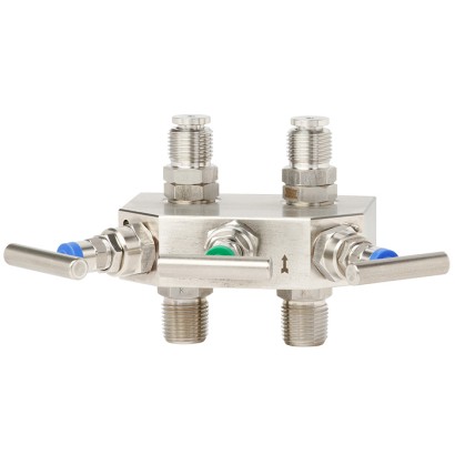
مجموعة صمامات (Manifold) لقياس الضغط التفاضلي لأجهزة القياس
الوصف
مجموعة صمامات (Valve manifold) مخصّصة لأجهزة قياس الضغط التفاضلي، وتتوفّر بنسختين: IV3 بثلاثة صمامات (صمامان إغلاق وصمام لمعادلة الضغط) وIV5 بخمسة صمامات (مع إضافة صمامَي تفريغ). تعمل مع الوسائط الغازية والسائلة شديدة العدوانية غير اللزجة وغير المتبلورة، وتُختار في صناعات النفط والغاز، والبتروكيماويات، والكيماويات، وتوليد الطاقة، والمياه ومياه الصرف الصحي.
المزايا
- تصميم منخفض التآكل بفضل طرف عمود دوّار غير دوار في الغطاء
- عزم دوران منخفض وحركة سلسة لمقبض الصمام حتى عند الضغوط العالية
- مسافات مركزية موحدة بمقدار 37 mm و 54 mm، مناسبة لمانومترات فرق الضغط من WIKA وأجهزة الإرسال العملية الشائعة الاستخدام
- مقعد صمام مُختبر للإحكام ضد التسرب وفق ISO 5208 بمعدل تسرب A
- سلامة تشغيلية معززة بفضل تصميم غطاء مقاوم للانفجار، خاصة في التطبيقات ذات الضغوط العالية
الأسئلة والأجوبة
ما الفرق بين طرازَي IV3 وIV5؟
يتكوّن بلوك صمام IV3 من صمامَي إغلاق وصمام لمعادلة الضغط، بينما يحتوي IV5 على صمامَي تفريغ إضافيين، أي أنه مجموعة من خمسة صمامات.
ما الحد الأقصى لضغط التشغيل؟
تتوفر المجموعة بثلاثة نطاقات ضغط: 0 … 206 bar، و0 … 420 bar، و0 … 690 bar حسب الطراز المختار.
ما مدى درجة حرارة الوسط المدعوم؟
تعمل المجموعة مع درجات حرارة وسط من -70 °C إلى +538 °C.
ما وصلات العملية المتاحة؟
تشمل الوصلات أحجام NPT من ¼ إلى ¾، وأحجام G من ¼ إلى ¾، بالإضافة إلى وصلات دوّارة ولحام وضغط، ووصلات فلنجة وفق IEC 61518 (Form A وForm B)، ووصلات Minimess 1215 و1620، و7/16" UNF، وG 1/2 B.
هل تناسب هذه المجموعة الوسائط العدوانية؟
نعم، فهي مصممة للوسائط الغازية والسائلة شديدة العدوانية غير عالية اللزوجة أو المتبلورة، مع توفر مواد للأجزاء الملامسة للوسط مثل Hastelloy C276 وMonel 400 وSuper Duplex F55 لتحمّل البيئات العدوانية.
هل هناك شهادات للمواد والتسرب؟
نعم؛ اجتاز مقعد الصمام اختبار الإحكام وفق ISO 5208 بمعدل تسريب A، وتشمل الموافقات NACE MR0175 / ISO 15156، وAPI 607، وAPI 6FA، وISO 15848-1، وTA-Luft (VDI 2440)، وPED، وEAC، وCRN، وغيرها.
لماذا يُقال إن التصميم آمن عند الضغوط العالية؟
يعزّز التصميم سلامة العمل بفضل غطاء مقاوم للطرد (blow-out proof)، كما أن طرف العمود غير الدوار يقلّل التآكل ويمنح تشغيلاً سلساً بعزم دوران منخفض حتى عند الضغوط العالية.
هل تتوافق المسافات المركزية مع أجهزة قياس أخرى؟
نعم، المسافات المركزية موحّدة عند 37 مم و54 مم، ما يجعلها مناسبة لمقاييس الضغط التفاضلي WIKA وأجهزة الإرسال العملية الشائعة الاستخدام.
اجمع IV3X لمهمتك
يُبنى رقم المادة تلقائيًا. عند الشك — تواصل مع مهندس؛ سنساعدك حسب معطيات الخط.
- Version3-Valve Manifold
- DesignStandard pattern, C-2-C instrument: 37mm
- Valve positionAngled, Differential Pressure Gauge
- Connection process side + instrument side1/2 NPT female - G 1/2 female swivel
- Material bodyStainless steel 316/316L - 1.4401/1.4404 - S31600/S31603
- Mounting—
- Vent connectionwithout
- Nominal pressure6000 psi / 420 bar
- Material packingPTFE
- Bonnet designStandard
- Bonnet optionswithout
- with padlockwithout
- Special design featureswithout
- Bolt for manifoldswithout
أكمل التهيئة
اختر جميع الخيارات لإرسال الطلب.
| الطراز | IV3 |
| السلسلة | IV3, IV5 |
| النوع الفرعي | Valve manifold |
| نطاق الضغط | 0…206 bar · 0…420 bar · 0…690 bar |
| وصلة العملية | ¼ NPT⅜ NPT½ NPT¾ NPTG ¼G ⅜G ½G ¾Swivel connectionWeld-in connectionCompression fittingFlange connection per IEC 61518, Form AFlange connection per IEC 61518, Form BMinimess 1215Minimess 16207/16" UNFG 1/2 B1/2 NPT |
| درجة حرارة العملية | −70…+538 °C |
| مادة العلبة | Stainless steel 316/316L (1.4401/1.4404), Stainless steel 321 (1.4541), Monel 400 (2.4360), Hastelloy C276 (2.4819), Stainless steel 6Mo (1.4547), Duplex F51 (1.4462), Super Duplex F55 (1.4501), Inconel 625 (2.4856), Incoloy 825 (2.4858), stainless steel 316Ti (1.4571), carbon steel |
| مادة الأجزاء الملامسة | Stainless steel 316/316L (1.4401/1.4404), Stainless steel 321 (1.4541), Monel 400 (2.4360), Hastelloy C276 (2.4819), Stainless steel 6Mo (1.4547), Duplex F51 (1.4462), Super Duplex F55 (1.4501), Inconel 625 (2.4856), Incoloy 825 (2.4858), stainless steel 316Ti (1.4571), carbon steel |
| مادة الإحكام | PTFE, Polar PTFE, Graphite, FKM, FKM AED, RTFE, SIGRAFLEX ZX graphite, SIGRAFLEX® ZX graphite |
| الشهادات | EACCRNPEDNACE MR0175 / ISO 15156ASME B31.1ISO 10497API 6FAAPI 607TA-Luft (VDI 2440)ISO 15848-1API 598ISO 5208 |
| لغات ورقة البيانات | EN, DE |
| Model | Description | Functional diagram | |
|---|---|---|---|
| IV304 | ■ 3-valve manifold ■ Centre distance on instrument side: 37 mm[1.46 in] ■ Angled bonnet position | Equalise | Shut off Shut off |
| IV315 | ■ 3-valve manifold ■ Centre distance on instrument side: 54 mm[2.12 in] ■ Radial bonnet position | Equalise | Shut off Shut off |
| IV319 ■ ■ | 3-valve manifold Centre distance on instrument side: 54 mm[2.12 in] ■ Angled bonnet position | Equalise Shut off Shut off | |
| IV313 | ■ 3-valve manifold ■ Centre distance on instrument side: 54 mm[2.12 in] ■ Side-by-side bonnet position | Equalise Shut off Shut off | |
| IV316 | ■ 3-valve manifold ■ Centre distance on instrument side: 54 mm[2.12 in] ■ Angled bonnet position ■ Direct flange mounting | Equalise Shut off Shut off | |
| IV318 | ■ 3-valve manifold ■ Centre distance on instrument side: 54 mm[2.12 in] ■ Angled bonnet position, equalising valve under 45° ■ Direct flange mounting | Equalise Shut off Shut off | |
| IV31V | ■ 3-valve manifold ■ Centre distance on instrument side: 54 mm[2.12 in] ■ Centre distance on process side: 110 mm[4.33 in] ■ Angled bonnet position ■ Direct flange mounting | Equalise Shut off Shut off | |
| IV31E | ■ 3-valve manifold ■ Centre distance on instrument side: 54 mm[2.12 in] ■ Radial bonnet position ■ Direct flange mounting | Equalise Shut off Shut off |
| Model | Description | Functional diagram |
|---|---|---|
| ■ 3-valve manifold ■ Centre distance on instrument side: 54 mm[2.12 in] ■ Angled bonnet position ■ H-shaped design ■ Direct flange mounting | Equalise Shut off Shut off | |
| ■ 3-valve manifold ■ Centre distance on instrument side: 54 mm[2.12 in] ■ Angled bonnet position ■ T-shaped design ■ Direct flange mounting | Equalise Shut off Shut off | |
| ■ 3-valve manifold ■ Centre distance on instrument side: 54 mm[2.12 in] ■ Angled bonnet position, equalising valve under 90° ■ Direct flange mounting with 90° angle connections | Equalise Shut off Shut off | |
| ■ 3-valve manifold ■ Centre distance on instrument side: 54 mm[2.12 in] ■ Angled bonnet position ■ Direct flange mounting with 90° angle connections ■ Special design for protective enclosures | Equalise Shut off Shut off | |
| ■ 3-valve manifold ■ Centre distance on instrument side: 54 mm[2.12 in] ■ Radial bonnet position ■ Integral flange mounting | Equalise Shut off Shut off | |
| ■ 3-valve manifold ■ Double block-and-bleed setup ■ Angled bonnet position | Shut off Shut off Vent |
| Model | Description | Functional diagram | |
|---|---|---|---|
| IV504 | ■ 5-valve manifold ■ Centre distance on instrument side: 37 mm[1.46 in] ■ Angled bonnet position | Equalise Vent off | Vent Shut Shut off |
| IV515 | ■ 5-valve manifold ■ Centre distance on instrument side: 54 mm[2.12 in] ■ Radial bonnet position | Vent off | Equalise Vent Shut Shut off |
| IV519 | ■ 5-valve manifold ■ Centre distance on instrument side: 54 mm[2.12 in] | ■ Angled bonnet position | Equalise Vent Vent Shut off Shut off |
| IV513 ■ | 5-valve manifold ■ Centre distance on instrument side: 54 mm[2.12 in] ■ Side-by-side bonnet position | Equalise Vent Vent Shut off Shut off | |
| IV516 | ■ 5-valve manifold ■ Centre distance on instrument side: 54 mm[2.12 in] ■ Angled bonnet position ■ Direct flange mounting | Equalise Vent Vent Shut off Shut off | |
| IV518 | ■ 5-valve manifold ■ Centre distance on instrument side: 54 mm[2.12 in] ■ Angled bonnet position, vent and equalising valves under 45° ■ Direct flange mounting | Equalise Vent Vent Shut off Shut off | |
| IV51V | ■ 5-valve manifold ■ Centre distance on instrument side: 54 mm[2.12 in] ■ Centre distance on process side: 110 mm[4.33 in] ■ Angled bonnet position ■ Direct flange mounting | Equalise Vent Vent Shut off Shut off | |
| IV51E | ■ 5-valve manifold ■ Centre distance on instrument side: 54 mm[2.12 in] ■ Radial bonnet position ■ Direct flange mounting | Equalise Vent Vent Shut off Shut off |
| Model | Description | Functional diagram | |
|---|---|---|---|
| IV51G | ■ 5-valve manifold ■ Centre distance on instrument side: 54 mm[2.12 in] ■ Radial bonnet position, equalising valve under 45° ■ Direct flange mounting | Equalise Vent Vent Shut off Shut off | |
| IV51H | ■ 5-valve manifold ■ Centre distance on instrument side: 54 mm[2.12 in] ■ Angled bonnet position ■ H-shaped design ■ Direct flange mounting | Equalise Vent Vent Shut off Shut off | |
| IV51T | ■ 5-valve manifold ■ Centre distance on instrument side: 54 mm[2.12 in] ■ Angled bonnet position ■ T-shaped design ■ Direct flange mounting | Equalise Vent Vent Shut off Shut off | |
| IV51D | ■ 5-valve manifold ■ Centre distance on instrument side: 54 mm[2.12 in] ■ Radial bonnet position, equalising valve under 90° ■ Direct flange mounting with 90° angle connections | Equalise Vent Vent Shut off Shut off | |
| IV51S | ■ 5-valve manifold ■ Centre distance on instrument side: 54 mm[2.12 in] ■ Radial bonnet position, equalising valve under 90° ■ Direct flange mounting with 90° angle connections ■ Special design for protective enclosures | Equalise Vent Vent Shut off Shut off | |
| IV51R | ■ 5-valve manifold ■ Centre distance on instrument side: 54 mm[2.12 in] ■ Radial bonnet position ■ Integral flange mounting | Equalise Vent Vent Shut off Shut off |
عرض الكل (17)
| Model | Description | Functional diagram | |
|---|---|---|---|
| IV529 | ■ 5-valve manifold ■ Centre distance on instrument side: 54 mm[2.12 in] ■ Angled bonnet position | Vent Shut off off Equalise | Shut |
| IV52V | ■ 5-valve manifold ■ Centre distance on instrument side: 54 mm[2.12 in] ■ Centre distance on process side: 110 mm[4.33 in] ■ Angled bonnet position ■ Direct flange mounting | Vent Shut off Equalise | Shut off |
| IV52G | ■ 5-valve manifold ■ Centre distance on instrument side: 54 mm[2.12 in] ■ Radial bonnet position, vent valve under 45° ■ Direct flange mounting | Vent Shut off Equalise | Shut off |
| IV52H | ■ 5-valve manifold ■ Centre distance on instrument side: 54 mm[2.12 in] ■ Angled bonnet position ■ H-shaped design ■ Direct flange mounting | Vent Shut off | Shut off Equalise |
| IV52T | ■ 5-valve manifold ■ Centre distance on instrument side: 54 mm[2.12 in] ■ Angled bonnet position ■ T-shaped design ■ Direct flange mounting | Vent Shut off Equalise | Shut off |
| IV52N | ■ 5-valve manifold ■ Centre distance on instrument side: 54 mm[2.12 in] ■ Angled bonnet position ■ H-shaped design ■ Direct flange mounting ■ Soft-seat through-bore bonnets for natural gas | Vent Shut off Equalise | Shut off |
| IV52N | ■ 5-valve manifold ■ Centre distance on instrument side: 54 mm[2.12 in] ■ Angled bonnet position ■ T-shaped design ■ Direct flange mounting ■ Soft-seat through-bore bonnets for natural gas | Vent Shut off | Shut off Equalise |
| Basic information | |
|---|---|
| Basic features | ■ Blow-out proof valve spindle ■ Non-rotating, low-wear spindle tip ■ Metal-to-metal back seat design |
| Special design features | ■ Without ■ For oxygen, oil- and grease-free ■ ASME B31.1, power piping (only available with graphite sealing packing) ■ Dielectric design 1) ■ Short process adapter, non-stabilised 1) ■ Long process adapter, stabilised 1) |
| Centre distance on instrument side | ■ 37 mm[1.46 in] ■ 54 mm[2.12 in], standard pattern ■ 54 mm[2.12 in], gas metering pattern |
| Standards used | |
| Basic design | ■ MSS SP-99, valves for measuring instruments ■ MSS SP-105, instrument valves for code applications ■ ASME B16.34, valves - flanged, threaded and welding end ■ ASME B1.20.1, pipe threads, general purpose (inch) ■ ASME B31.3, process piping ■ ASME BPVC, section VIII, division 1 |
| Special design | ■ Without ■ ISO 10497, API 6FA and API 607, type test for fire safety ■ TA-Luft (VDI 2440) and ISO 15848-1, type test for fugitive emissions |
| Tests | MSS SP-61, pressure testing of valves |
| Special tests | ■ Without ■ API 598, valve inspection and testing ■ ISO 5208, pressure testing of metallic valves with leakage rate A |
| Material requirements | NACE MR0175 / ISO 15156, use in H₂S-containing environments in oil and gas production |
| Special material requirements | ■ Without ■ NORSOK M-630, specification for use in pipelines (Norway) |
| Marking | MSS SP-25, standard marking system for valves |
| Mounting | ■ Without mounting holes ■ Suitable for mounting bracket, with mounting holes 2) |
| Bonnet | |
|---|---|
| Bonnet position | ■ Angled ■ Angled, equalising valve under 45° ■ Angled, vent and equalising valves under 45° ■ Radial ■ Radial, equalising valve under 45° ■ Radial, vent valve under 45° ■ Radial, equalising valve under 90° ■ Side-by-side |
| Bonnet design | ■ Screwed bonnet, 4 mm[0.16 in] bore size ■ Bonnet with extended handle, 4 mm[0.16 in] bore size ■ Miniature bonnet, 4 mm[0.16 in] bore size ■ Cryogenic bonnet for medium temperatures to -196 °C [-320 °F], 4 mm[0.16 in] bore size ■ OS&Y bonnet, bolted, 6 mm[0.24 in] bore size 1) ■ Bolted bonnet, 8 mm[0.31 in] bore size ■ Soft-seat through-bore bonnet for natural gas, only for model IV52N → For bonnet design, see page 10 |
| Bonnet variant | ■ Without ■ Anti-tamper for shut-off, pressure equalising and vent valve, padlock not included ■ Anti-tamper for shut-off, pressure equalising and vent valve, padlock included ■ Anti-tamper for pressure equalising and vent valve, padlock not included ■ Anti-tamper for pressure equalising and vent valve, padlock included ■ Anti-tamper for vent valve, padlock not included ■ Anti-tamper for vent valve, padlock included ■ Small T-handle ■ T-handle from stainless steel 316L (1.4404) |
|---|
| Process connection / Instrument connection | ||
|---|---|---|
| Standard | ■ Threaded connection per ANSI B1.20.1, code NPT ■ Threaded connection per ISO 228-1, codeG ■ Swivel connection ■ Weld-in connection ■ Compression fitting ■ Flange connection per IEC 61518, Form A or Form B 1) ■ Special design for protective enclosures ■ 90° angle connections Direct flange mounting | |
| Size | ■ ¼NPT ■ ⅜NPT ■ ½NPT ■ ¾NPT | ■ G¼ ■ G⅜ ■ G½ ■ G¾ |
| Vent connection | ■ ¼NPTfemale, plug screw included ■ ½NPTfemale, plug screw included ■ ¼NPTfemale with installed bleeder screw ■ G¼female, plug screw included ■ G½female, plug screw included ■ ¼NPTfemale, plug screw included and bleeder screw installed |
| Permissible operating pressure | ■ ≤ 3,000 psi or ≤ 206 bar ■ ≤ 6,000 psi or ≤ 420 bar ■ ≤ 10,000 psi or ≤ 690 bar 1) |
|---|---|
| Pressure and temperature limits | The limits for operating pressure and temperature depend on the version and the sealing material. → For diagram, see page 12 |
| Wetted parts | ||
|---|---|---|
| Valve body, bonnet body | ■ Stainless steel 316/316L (1.4401/1.4404) ■ Stainless steel 321 (1.4541) ■ Monel 400 (2.4360) ■ Hastelloy C276 (2.4819) | ■ Stainless steel 6Mo (1.4547) ■ Duplex F51 (1.4462) ■ Super Duplex F55 (1.4501) ■ Inconel 625 (2.4856) ■ Incoloy 825 (2.4858) |
| Spindle tip | ■ Stainless steel 316/316L (1.4401/1.4404) ■ Monel 400 (2.4360) ■ Hastelloy C276 (2.4819) | ■ Duplex F51 (1.4462) ■ Inconel 625 (2.4856) ■ Hardfaced with Stellite 6 |
| Sealing packing | ■ PTFE, temperature range: -55 ...+210 °C [-67 ...+410 °F] ■ Polar PTFE, temperature range: -70 ...+210 °C [-94 ...+410 °F] ■ Graphite, temperature range: -55 ...+538 °C [-67 ... +1,000 °F] ■ SIGRAFLEX ® ZX graphite, nuclear quality, temperature range: -55 ...+538 °C [-67 ... +1,000 °F] ■ FKM 1) , temperature range: -29 ...+180 °C [-20 ...+356 °F] ■ FKM AED 1) 2) , temperature range: -46 ...+180 °C [-50 ...+356 °F] ■ RTFE 3) , temperature range: -55 ...+180 °C [-67 ...+356 °F] | |
| Non-wetted parts | ||
| Gland nut, valve spindle, sealing bush, locking nut, locking pin | Stainless steel | |
| Handle | ■ Stainless steel 303 (1.4305) |
| Sealing packing | Max. allowable operating pressure at defined temperatures | |||
|---|---|---|---|---|
| Minimum temperature | Temperature of 0 °C [32 °F] | Temperature of 20 °C [68 °F] | Maximum temperature | |
| PTFE | 690 bar at -55 °C | 690 bar | 690 bar | 276 bar at 210 °C |
| 10,000 psi at -67 °F | 10,000 psi | 10,000 psi | 4,000 psi at 410 °F | |
| Polar PTFE | 690 bar at -70 °C | 690 bar | 690 bar | 276 bar at 210 °C |
| 10,000 psi at -94 °F | 10,000 psi | 10,000 psi | 4,000 psi at 410 °F | |
| Graphite or SIGRAFLEX® ZX graphite | 420 bar at -55 °C | 420 bar | 420 bar | 206 bar at 538 °C |
| 6,000 psi at -67 °F | 6,000 psi | 6,000 psi | 2,987 psi at 1,000 °F | |
| FKM | 206 bar at -29 °C | 206 bar | 206 bar | 206 bar at 180 °C |
| 2,987 psi at -20 °F | 2,987 psi | 2,987 psi | 2,987 psi at 356 °F | |
| FKM AED | 206 bar at -46 °C | 206 bar | 206 bar | 206 bar at 180 °C |
| 2,987 psi at -50 °F | 2,987 psi | 2,987 psi | 2,987 psi at 356 °F | |
| RTFE 1) | 420 bar at -55 °C | 420 bar | 420 bar | 276 bar at 180 °C |
| 6,000 psi at -67 °F | 6,000 psi | 6,000 psi | 4,000 psi at 356 °F |
| Logo | Description | Country |
|---|---|---|
| EAC Pressure Equipment Directive | Eurasian Economic Community | |
| - | Bureau Veritas Ships, shipbuilding (e.g. offshore) | International |
| - | CRN Safety (e.g. electr. safety, overpressure, ...) | Canada |
| Logo | Description |
|---|---|
| - | Information on Pressure Equipment Directive (PED) Design, manufacturing and testing carried out in accordance with sound engineering practise |
| - | PMI 1) test certificate Valve body |
| - | Hydrogen for general use 2) Suitable for general hydrogen applications under the following conditions: - Material proof for all wetted parts per MR0175 - Temperature range -55 ...+210 °C [-67 ...+410 °F] - Max. allowable operating pressure: 6,000 psi [420 bar] at 20 °C [68 °F] - With fugitive emission protection in accordance with TA-Luft (VDI 2440) and ISO 15848-1 |
| - | Oil- and grease-free per ASTM G93-03 level C (< 66 mg/m 2 ) - Sealing packing and lubricants in accordance with BAM requirements - Suitable for oxygen applications under the following temperature and pressure conditions (BAM): PTFE sealing packing: T ≤ 150 °C [302 °F] p ≤ 20 bar [290 psi] Graphite sealing packing: T ≤ 250 °C [482 °F] p ≤ 150 bar [2,175 psi] |
| - | Type tested for fire safety in accordance with API 607, ISO 10497, BS 6755-2 3) |
| - | Fugitive emission protection in accordance with TA-Luft (VDI 2440) and ISO 15848-1 - Tightness class:AH - Endurance class:C01 - Temperature class: -29 ...+180 °C [-20 ...+356 °F] |
| Certificates | 3.1 inspection certificate per EN 10204 - Material proof for all wetted parts per NACE MR0175 - Confirmation of pressure tests per MSS SP-61 1) - Confirmation of pressure tests per API 598or API 6D |
|---|
| For models | Centre distance on instrument side | Pipe alignment (models shown are examples) | Order number |
|---|---|---|---|
| IV316, IV318, IV31V, IV516, IV518, IV519, IV51G, IV51V | 54 mm[2.12 in] | Horizontal Horizontal | 14267553 |
| IV315, IV316, IV318, IV31V, IV516, IV518, IV519, IV51G, IV51V | 54 mm[2.12 in] | 14289800 | |
| IV304, IV504 | 37 mm[1.46 in] | Horizontal or vertical | 81509393 |
| IV504 | 37 mm[1.46 in] | Vertical | 14474946 |
| IV31H, IV31T, IV52H, IV52T | 54 mm[2.12 in] | Horizontal or vertical | 81509385 |
| IV51H, IV51T | 54 mm[2.12 in] | Horizontal or vertical | 81509391 |
| IV31R, IV51R | 54 mm[2.12 in] | Horizontal | 81509395 |
| IV319 | 54 mm[2.12 in] | Vertical | 81653990 |
| IV313 | 54 mm[2.12 in] | Vertical | 81509384 |
| IV31E, IV51E | 54 mm[2.12 in] | Vertical | 81647826 |
| IV31R, IV51R | 54 mm[2.12 in] | Vertical | 81509387 |
| IV515 | 54 mm[2.12 in] | Vertical | 81509389 |
| IV529 | 54 mm[2.12 in] | Vertical | 81509396 |
| Description | Order number |
|---|---|
| Anti-tamper key, stainless steel 303 (1.4305) | 81640006 |
| Adapter ½NPT, female - ¾NPT, male, stainless steel 316/316L (1.4401/1.4404) | 81655622 |
| Adapter ½NPT, male - ¼NPT;female, stainless steel 316/316L (1.4401/1.4404) | 81655620 |
| Bleeder screw ¼NPT, stainless steel 316/316L (1.4401/1.4404) | 81652317 |
| Plug screw ½NPT, stainless steel 316/316L (1.4401/1.4404) | 81652353 |
| Plug screw ¼NPT, stainless steel 316/316L (1.4401/1.4404) | 81652350 |
| Plug screw G¼, male, stainless steel 316/316L (1.4401/1.4404) | 81652351 |
| 2 x PTFE seal forG½ | 81657706 |
| 2 x PTFE seal for flange connection per IEC 61518, Form A | 81657688 |
| 2 x PTFE seal for flange connection per IEC 61518, Form B | 81657693 |
| 2 x Graphite seal forG½ | 81657707 |
| 2 x Graphite seal for flange connection per IEC 61518, Form A | 81657692 |
| 2 x Graphite seal for flange connection per IEC 61518, Form B | 81657696 |
| 4 x threaded bolt 7/16" UNF - 1", stainless steel 316/316L (1.4401/1.4404) | 81655985 |
| 4 x threaded bolt 7/16" UNF - 1 ¾", stainless steel 316/316L (1.4401/1.4404) | 81655988 |
| 4 x threaded bolt 7/16" UNF - 2", stainless steel 316/316L (1.4401/1.4404) | 81655982 |
| 4 x threaded bolt 7/16" UNF - 2 ¾", stainless steel 316/316L (1.4401/1.4404) | 81655984 |
| Adapter Minimess 1215 - ¼NPT, male, carbon steel | 81655625 |
| Adapter Minimess 1620 - G¼, male, stainless steel 316Ti (1.4571) | 14503075 |
| Swivel adapter ½NPT, male - ½NPT, female, max. pressure 10,000 psi [690 bar], stainless steel 316/316L (1.4401/1.4404) | 81655619 |
| Swivel adapter ½NPT, male - G½, female, with retaining ring, max. pressure 6,000 psi [420 bar], stainless steel 316/316L (1.4401/1.4404) | 81655624 |
| Swivel adapter G⅜A,male - G½A,male, max. pressure 6,000 psi [420 bar], stainless steel 316/316L (1.4401/1.4404) | 81655618 |
| Swivel adapter G⅜A,male - G¼A,male, max. pressure 6,000 psi [420 bar], stainless steel 316/316L (1.4401/1.4404) | 81655617 |
| Swivel adapter G⅜A,male - G½, female, with retaining ring, max. pressure 6,000 psi [420 bar], stainless steel 316/316L (1.4401/1.4404) | 81655621 |
| Swivel adapter G½, male - G½, female, with retaining ring, max. pressure 6,000 psi [420 bar], stainless steel 316/316L (1.4401/1.4404) | 81655623 |
| Adapter tube fitting 6 mmOD-¼NPT,male, stainless steel 316/316L (1.4401/1.4404) | 81643499 |
| Adapter tube fitting 10 mmOD-⅜NPT,female, stainless steel 316/316L (1.4401/1.4404) | 81643536 |
| Adapter tube fitting 6 mmOD-½NPT,female, stainless steel 316/316L (1.4401/1.4404) | 81643562 |
| Adapter tube fitting 12 mmOD-⅜NPT,male, stainless steel 316/316L (1.4401/1.4404) | 81643526 |
لم تجد الإجابة في الوثائق؟ سيرد المهندس خلال يوم عمل.
اسأل المهندس →2 مادة قياسية من عائلة IV3, IV5
إذا كنت تعرف الرمز — اختر مباشرة. إذا لا — استخدم المُهيِّئ في الوضع «01».