
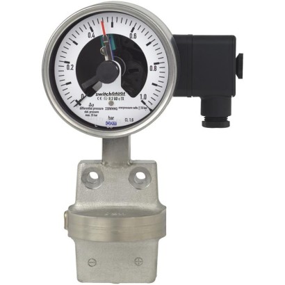
مقياس ضغط تفاضلي مع جهات تلامس (مفاتيح)
الوصف
حيثما يلزم بيان ضغط العملية محليًا وفي الوقت نفسه يلزم تبديل الدوائر، فإن مقياس التبديل switchGAUGE لطراز DPGS43.1x0 يُستخدم لهذا الغرض.
تقوم جهات التلامس الخاصة بالمفتاح (جهات تلامس إنذار كهربائية) بفتح أو إغلاق الدوائر اعتمادًا على موضع المؤشر الخاص بمقياس الضغط. يمكن ضبط جهات التلامس الخاصة بالمفتاح على كامل مدى نطاق السلم (انظر DIN 16085)، ويتم تركيبها بشكل أساسي أسفل وجه الساعة، على الرغم من أنها قد تكون أيضًا جزئيًا فوق وجه الساعة. يتحرك مؤشر الجهاز (مؤشر القيمة الفعلية) بحرية عبر كامل مدى السلم، بغض النظر عن الإعداد.
يمكن ضبط المؤشر المُعين باستخدام مفتاح ضبط قابل للإزالة عبر النافذة.
المزايا
- مدى قياس فرق الضغط من 0 ... 16 mbar
- ضغط تشغيل مرتفع (الضغط الساكن) وأمان تحميل زائد مرتفع حتى 40 bar
- متوفر أيضاً بعلبة معبأة بسائل لتحملات ضغط ديناميكية عالية أو اهتزازات
- أجهزة بنقاط اتصال حثية للاستخدام في المناطق الخطرة
- أجهزة ذات ملامس تبديل لتطبيقات PLC
الأسئلة والأجوبة
ما هي نطاقات القياس المتاحة لهذا الجهاز؟
يتوفر الجهاز بنطاقات قياس ضغط تفاضلي: 0 ... 16 mbar، 0 ... 250 mbar، 0 ... 400 mbar، و0 ... 40 bar.
ما دقة القياس؟
فئة الدقة 1.6 وفق المعيار EN 837-3.
ما هي وصلات العملية المتاحة؟
الوصلات المتاحة هي G ¼ B أنثوي، G ½ B ذكري، و½ NPT ذكري.
هل يمكن استخدام الجهاز في المناطق الخطرة؟
نعم، تتوفر نسخ بجهات تلامس حثّية معتمدة للاستخدام في المناطق الخطرة وفق ATEX وIECEx وEAC وNEPSI وEx Ukraine، بتصنيف II2G Ex ia IIC T6/T5/T4 Gb وII2D Ex ia IIIB T135℃ Db.
ما هي حدود درجات الحرارة للتشغيل؟
درجة حرارة البيئة المحيطة من -20 … +80 °C، ودرجة حرارة الوسط من -20 … +100 °C.
ما هو مستوى الحماية من الغبار والماء؟
تصنيف الحماية IP54.
ما الذي يميز هذا الطراز عن المقاييس العادية؟
يجمع بين الإظهار المحلي لفرق الضغط والتبديل الكهربائي للدوائر عبر حتى 4 جهات تلامس، مع حجرة وسيط معدنية بالكامل وأمان تحميل زائد حتى 40 bar، وخيار علبة معبأة بسائل للأحمال الديناميكية أو الاهتزازات.
ما هي إشارات الخروج المتاحة؟
Reed switch، جهة تلامس حثّية، جهة تلامس إلكترونية، Magnetic snap-action contact، وترانزستور PNP، بتغذية DC 10...30V.
| الطراز | DPGS43.100 |
| السلسلة | DPGS43 |
| النوع الفرعي | Differential pressure gauge with switch |
| نطاق الضغط | 0…16 mbar · 0…250 mbar · 0…400 mbar · 0…40 bar |
| فئة الدقة | 1.6 |
| معيار الدقة | EN 837-3 |
| وصلة العملية | G ¼ B femaleG ½ B male½ NPT maleG1/2B femaleG1/2B male1/2NPT male |
| درجة حرارة العملية | −20…+100 °C |
| إشارة الخرج | Reed switch · Inductive contact · Electronic contact · Magnetic snap-action contact · PNP transistor |
| التغذية | DC 10...30V |
| وصلة كهربائية | Cable socket PA 6, black, M20 x 1.5 |
| وظيفة التبديل | Normally open (clockwise pointer motion), Normally closed (clockwise pointer motion), Change-over |
| نقاط التبديل | 4 |
| مادة العلبة | Stainless steel |
| مادة الأجزاء الملامسة | Stainless steel 316Ti (1.4571), NiCr alloy (Inconel), Stainless steel 316L, Bellows: Stainless steel 316Ti (1.4571) |
| حرارة المحيط | −20…+80 °C |
| تصنيف IP | IP54 |
| الشهادات | CELow voltage directiveEMCRoHSREACHPressure Equipment DirectiveEMC directiveMetrology, measurement technologyPressure equipmentLow voltageGOSTKazInMetrBelGIMUkrSEPROUzstandard |
| حماية الانفجار | [II 2G Ex ia IIC T6/T5/T4 Gb] [II 2D Ex ia IIIB T135°C Db][Ex ia IIC T6/T5/T4 Gb] [Ex ia IIIB T135°C Db]ATEXIECExEACNEPSIEx UkraineII2G Ex ia IIC T6/T5/T4 GbII2D Ex ia IIIB T135℃ DbEx ia IIC T6/T5/T4 GbEx ia IIIB T135℃ Db |
| قطر القرص | 100 mm |
| لغات ورقة البيانات | EN, DE |
| Version | Process connections lower mount or lateral (option), highly corrosion-resistant solid metal design, measuring cell protected against unauthorised access. Overload resistance per EN 837-3 |
|---|---|
| Nominal size inmm | ■ 100 ■ 160 |
| Accuracy class | 1.6 Option: 1.0 on request |
| Scale ranges | 0 ... 16 mbar to 0 ... 250 mbar 0 ... 400 mbar to 0 ... 40 bar other units (e.g. psi, kPa) available or all other equivalent vacuum or combined pressure and vacuum ranges |
| Scale | Single scale Option: ■ Dual scale ■ Scale layout (e.g. linear pressure or square root incrementation) |
| Zero point setting | Without Option: Zero point adjustment appliance |
| Pressure limitation | |
| Steady | Full scale value |
| Fluctuating | 0.9 x full scale value Observe the recommendations for the use of mechanical pressure measuring systems in accord- ance with EN 837-2 |
| Overpressure safety and max. working pressure (static pressure) | see table on page 3 |
| Connection location | Lower mount (radial) Option: lateral (right, left, front or back) |
| Process connection | ■ G¼Bfemale ■ G½Bmale ■ ½NPTmale Other process connections via female or male threads on request |
| Restrictor | Without Option: Restrictor in the pressure port |
| Permissible temperature 1) | |
| Medium | -20 ...+100 °C Option: Medium temperature > 100 °C on request |
| Ambient | -20 ...+60 °C (with window from polycarbonate max. 80 °C) |
| Temperature effect | When the temperature of the measuring system deviates from the reference temperature (+20 °C): max. ±0.5 %/10 K of full scale value |
| Case | ■ Version S1 per EN 837:With blow-out device in case back ■ Safety version S3 per EN 837:With solid baffle wall (Solidfront) and blow-out back |
| Case filling | Without Option: With case filling |
| Venting of the media chamber | With scale ranges ≤ 0.25 bar Option: With scale ranges ≥ 0.4 bar |
| Wetted materials | |
|---|---|
| Media chamber with process connection | Stainless steel 316Ti (1.4571) Lower mount 2 x G¼female |
| Pressure elements | ≤ 0.25 bar: Stainless steel 316L > 0.25 bar: NiCr alloy (Inconel) |
| Venting of the media chamber | Stainless steel 316Ti (1.4571) for scale ranges ≤ 0.25 bar Option: with scale ranges ≥ 0.4 bar |
| Bellows | Stainless steel 316Ti (1.4571) |
| Non-wetted materials | |
| Movement | Brass |
| Dial | Aluminium, white, black lettering |
| Pointer | Aluminium, black |
| Case | Stainless steel, with blow-out device |
| Window | Laminated safety glass |
| Ring | Bayonet ring, stainless steel |
| Ingress protection per IEC/EN 60529 | IP54 1 ) Option: IP65 with liquid filling |
| Installation | according to affixed symbols:⊕high pressure, ⊖low pressure |
| Mounting | ■ Rigid measuring lines ■ Mounting holes in measuring flange Option: ■ Panel mounting flange ■ Instrument mounting bracket for wall or pipe mounting |
| Electrical connection | Cable socket PA 6, black PerVDE 0110 insulation group C/250V Cable gland M20 x 1.5 Strain relief 6 screw terminals + PE for conductor cross-section 2.5 mm² For dimensions see page 10 others on request |
| Scale ranges | Overload safety in bar either side max. | Max. working pressure in bar (static pressure) | ||
|---|---|---|---|---|
| Standard | Option | Standard | Option | |
| 0 ... 16 to 0 ... 40 mbar | 2.5 | - | 2.5 | 6 2) |
| 0 ... 60 to 0 ... 250 mbar | 2.5 | 6 | 6 | 10 |
| 0 ... 400 mbar | 4 | 40 | 25 | 40 |
| 0 ... 0.6 bar | 6 | 40 | 25 | 40 |
| 0 ... 1 bar | 10 | 40 | 25 | 40 |
| 0 ... 1.6 bar | 16 | 40 | 25 | 40 |
| 0 ... 2.5 to 0 ... 25 bar | 25 | 40 | 25 | 40 |
| Measuring span | Nominal size | Max. number of contacts | Switching current range I | Switch version 1) |
|---|---|---|---|---|
| ≤ 1.0 bar | 100, 160 | 1 | 0.02 ... 0.3 A | L |
| > 1.0 bar | 100, 160 | 1 | 0.02 ... 0.6 A | S |
| ≤ 1.6 bar | 100, 160 | 2 | 0.02 ... 0.3 A | L |
| > 1.6 bar | 100, 160 | 2 | 0.02 ... 0.6 A | S |
| ≤ 4.0 bar | 100 | 4 | 0.02 ... 0.3 A | L |
| > 4.0 bar | 100 | 4 | 0.02 ... 0.6 A | S |
| ≤ 2.5 bar | 160 | 4 | 0.02 ... 0.3 A | L |
| > 2.5 bar | 160 | 4 | 0.02 ... 0.6 A | S |
عرض الكل (20)
| Characteristics | Unfilled instruments | Filled instruments | ||
|---|---|---|---|---|
| Resistive load | Resistive load | |||
| Switch version 'S' | Switch version 'L' | Switch version 'S' | Switch version 'L' | |
| Rated operating voltage U eff | ≤ 250V | ≤ 250V | ||
| Rated operating current | ||||
| Switch-on current | ≤ 1.0 A | ≤ 0.5 A | ≤ 1.0 A | ≤ 0.5 A |
| Switch-off current | ≤ 1.0 A | ≤ 0.5 A | ≤ 1.0 A | ≤ 0.5 A |
| Continuous current | ≤ 0.6 A | ≤ 0.3 A | ≤ 0.6 A | ≤ 0.3 A |
| Switching power | ≤ 30W/ ≤ 50VA | ≤ 20W/ ≤ 20VA |
| Operating voltage | Unfilled instruments | Filled instruments | ||||
|---|---|---|---|---|---|---|
| Resistive load | Inductive load | Resistive load | Inductive load | |||
| Direct current | Alter - nating current | cos ϕ>0.7 | Direct current | Alter - nating current | cos ϕ>0.7 | |
| DC 220 V / AC 230 V | 100mA | 120mA | 65mA | 65mA | 90mA | 40mA |
| DC 110 V / AC 110 V | 200mA | 240mA | 130mA | 130mA | 180mA | 85mA |
| DC 48 V / AC 48 V | 300mA | 450mA | 200mA | 190mA | 330mA | 130mA |
| DC 24 V / AC 24 V | 400mA | 600mA | 250mA | 250mA | 450mA | 150mA |
| Measuring span | Nominal size | Case version | Max. number of contacts |
|---|---|---|---|
| 0.6 bar | 100, 160 | S1 | 1 |
| 0.6 bar | 160 | S3 | 1 |
| 1.0 bar | 100, 160 | S1 | 2 |
| 1.0 bar | 100 | S3 | 1 |
| 1.0 bar | 160 | S3 | 2 |
| ≥ 1.6 bar | 100, 160 | S1, S3 | 3 |
| T6 | T5 ...T1 | T135°C |
|---|---|---|
| -20 ...+60 °C | -20 ...+70 °C | -20 ...+70 °C |
| Model | Version | Ex version |
|---|---|---|
| 904.28 KFA6 - SR2 - Ex1.W | 1 contact | yes |
| 904.29 KFA6 - SR2 - Ex2.W | 2 contacts | yes |
| 904.30 KHA6 - SH - Ex1 | 1 contact | yes - safety equipment |
| 904.33 KFD2 - SH - Ex1 | 1 contact | yes - safety equipment |
| 904.25 MSR 010-I | 1 contact | no |
| 904.26 MSR 020-I | 2 contacts | no |
| 904.27 MSR 011-I | Two-point control | no |
| Measuring span | Nominal size | Case version | Max. number of contacts |
|---|---|---|---|
| 0.6 bar | 100, 160 | S1 | 1 |
| 0.6 bar | 160 | S3 | 1 |
| 1.0 bar | 100, 160 | S1 | 2 |
| 1.0 bar | 100 | S3 | 1 |
| 1.0 bar | 160 | S3 | 2 |
| ≥ 1.6 bar | 100, 160 | S1, S3 | 2 |
| Contact version | Normally open, normally closed |
|---|---|
| Type of output | PNP transistor |
| Operating voltage | DC 10 ...30V |
| Residual ripple | max.10% |
| No-load current | ≤ 10mA |
| Switching current | ≤ 100mA |
| Residual current | ≤ 100 µA |
| Voltage drop (with I max. ) | ≤ 0.7V |
| Reverse polarity protection | Conditional U B (the switched output 3 or 4 must never be set directly to minus) |
| Anti-inductive protection | 1 kV, 0.1 ms, 1 kΩ |
| Oscillator frequency | approx. 1,000 kHz |
| EMC | per EN 60947-5-2 |
| Measuring span | Nominal size | Max. number of contacts |
|---|---|---|
| ≥ 16 mbar | 100, 160 | 2 |
| Characteristics | |
|---|---|
| Contact version | Change-over contact |
| Type of contact | Bistable |
| Max. switching voltage | AC/DC 250V |
| Min. switching voltage | Not required |
| Switching current | AC/DC 1 A |
| Min. switching current | Not required |
| Transport current | AC/DC 2 A |
| cosϕ | 1 |
| Switching power | 60W/VA |
| Contact resistance (static) | 100mΩ |
| Insulation resistance | 10 9 Ω |
| Breakdown voltage | DC 1,000V |
| Switching time incl. contact chatter | 4.5 ms |
| Contact material | Rhodium |
| Switch hysteresis | 3 ...5% |
| Logo | Description | Country |
|---|---|---|
| EU declaration of conformity ■ EMCdirective ■ Pressure equipment directive ■ ATEX directive (option) 1) Hazardous areas | European Union | |
| IECEx (option) 1) Hazardous areas Ex ia Gas [Ex ia IIC T6/T5/T4 Gb] Dust [Ex ia IIIB T135°C Db] | International | |
| EAC (option) ■ EMCdirective ■ Pressure equipment directive ■ Low voltage directive ■ Hazardous areas 1) | Eurasian Economic Community | |
| GOST (option) Metrology, measurement technology | Russia | |
| KazInMetr (option) Metrology, measurement technology | Kazakhstan | |
| - | MTSCHS (option) Permission for commissioning | Kazakhstan |
| BelGIM (option) Metrology, measurement technology | Belarus | |
| UkrSEPRO (option) Metrology, measurement technology | Ukraine | |
| Ex Ukraine (option) 1) Hazardous areas | Ukraine | |
| Uzstandard (option) Metrology, measurement technology | Uzbekistan | |
| NEPSI (option) 1) Hazardous areas | China | |
| - | CRN Safety (e.g. electr. safety, overpressure, ...) | Canada |
| Type of contact | Dimensions inmm | |
|---|---|---|
| X | Y | |
| Single or double contact | 88 | 55 |
| Double (change-over) contact | 113 | 80 |
| Triple contact | 96 | 63 |
| Quadruple contact | 113 | 80 |
| Process connection | Dimensions inmm | |||||
|---|---|---|---|---|---|---|
| h ±1 | S2 | S3 | S4 | S5 | S6 | |
| G½B | 203 | 6 | 20 | 3 | 17 | 17.5 |
| ½NPT | 201 | - | 19 | - | - | - |
| Type of contact | Dimensions inmm X |
|---|---|
| Single or double contact | 102 |
| Double (change-over) contact | 116 |
| Triple contact | 102 |
| Quadruple contact | 116 |
| Process connection | Dimensions inmm | |||||
|---|---|---|---|---|---|---|
| h ±1 | S2 | S3 | S4 | S5 | S6 | |
| G½B | 233 | 6 | 20 | 3 | 17 | 17.5 |
| ½NPT | 231 | - | 19 | - | - | - |
| Scale range | Dimensions inmm | ||
|---|---|---|---|
| Ø d | h ±1 | H ±1 | |
| ≤ 0.25 bar | 140 | 161 | 90 |
| > 0.25 bar | 78 | 171 | 87 |
| Scale range | Dimensions inmm | ||
|---|---|---|---|
| Ø d | h ±1 | H ±1 | |
| ≤ 0.25 bar | 140 | 201 | 117 |
| > 0.25 bar | 78 | 190 | 120 |
لم تجد الإجابة في الوثائق؟ سيرد المهندس خلال يوم عمل.
اسأل المهندس →