
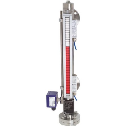
مؤشر مستوى الالتفاف
الوصف
مؤشر مستوى التجاوز طراز BNA يتكوّن من حجرة تجاوز يتم تثبيتها على جانب الخزان كوعاء تواصلي عبر ما لا يقل عن 2 من وصلات العملية (وصلة شفة، اقتران ملولب أو قطعة لحام قصيرة). ومن خلال هذا النوع من الترتيب، يتوافق مستوى السائل في حجرة التجاوز مع مستوى السائل في الوعاء. يقوم العائم المزود بنظام مغناطيسي دائم مدمج، والذي يتم تركيبه داخل حجرة التجاوز، بنقل مستوى السائل، دون تلامس، إلى شاشة العرض المغناطيسية المثبتة على خارج حجرة التجاوز. وفي هذه الشاشة يتم تركيب، على فواصل 10 mm، بكرات بلاستيكية ثنائية اللون أو صفائح من الفولاذ المقاوم للصدأ مزودة بمغناطيسات شريطية.
للموافقات الإضافية، راجع الصفحة 4
مؤشر مستوى التجاوز، طراز BNA مع حساس مستوى ومفتاح مغناطيسي
من خلال المجال المغناطيسي للنظام المغناطيسي الدائم في العائم، يتم تدوير عناصر العرض، عبر جدار حجرة التجاوز، بمقدار 180°. بالنسبة لارتفاع المستوى من الأبيض إلى الأحمر؛ وبالنسبة لانخفاض المستوى من الأحمر إلى الأبيض. وبذلك يعرض مؤشر مستوى التجاوز بوضوح مستوى
وعاء دون جهد إمداد.
المزايا
- إنتاج خاص بالعملية والنظام
- حدود التشغيل: درجة حرارة التشغيل: T = -196 ... +450 °C ضغط التشغيل: P = من الفراغ إلى 400 bar الكثافة الحدية: ρ ≥ 340 kg/m3
- درجة حرارة التشغيل: T = -196 ... +450 °C
- ضغط التشغيل: P = تفريغ حتى 400 bar
- الكثافة الحدية: ρ ≥ 340 kg/m 3
- تشكيلة واسعة من وصلات العمليات والمواد المختلفة
- إمكانية تركيب محولات المستوى والمفاتيح المغناطيسية كخيار
- نسخ مقاومة للانفجار
الأسئلة والأجوبة
ما هو مبدأ عمل مؤشر مستوى BNA؟
يعتمد على عائم مزود بنظام مغناطيسي دائم داخل حجرة التجاوز المتصلة جانبيًا بالوعاء، حيث ينقل المستوى دون تلامس عبر جدار الحجرة إلى شاشة عرض مغناطيسية تدور بمقدار 180°.
هل يحتاج المؤشر إلى مصدر تغذية؟
لا، يوفر عرضًا مستمرًا للمستوى دون جهد إمداد، ويمكن تركيب حساسات مستوى ومفاتيح مغناطيسية كخيار عند الحاجة إلى إشارات كهربائية.
ما هو مدى القياس؟
من 0,15 m إلى 6,0 m.
ما هي حدود درجة الحرارة والضغط في التشغيل؟
درجة حرارة التشغيل T = -196 … +450 °C، وضغط التشغيل P = تفريغ حتى 400 bar، بشرط كثافة حدية ρ ≥ 340 kg/m³.
ما هي وصلات العملية المتاحة؟
شفة EN 1092-1 (DN 10…100، PN 6…100)، شفة ANSI B16.5 (1/2"…4"، class 150…900)، قطعة لحام 1/2"…1"، ووصلات ملولبة G1/2…1 أو 1/2…1 NPT.
ما هي المواد المتاحة للأجزاء الملامسة للوسط؟
PP، PVDF، طلاء E-CTFE أو PTFE، الفولاذ المقاوم للصدأ 1.4571 (316Ti) و1.4401/1.4404 (316/316L) و6Mo 1.4547 (UNS S31254)، التيتانيوم 3.7035، وHastelloy C276 (2.4819).
هل تتوفر نسخ مقاومة للانفجار؟
نعم، بشهادات ATEX وIECEx لمناطق الغاز Zone 0/1 وZone 2 ومناطق الغبار، مثل II 1/2G Ex h IIC T6…T1 Ga/Gb وII -/2D Ex h IIIC T68…T360°C -/Db.
لماذا يُختار طراز BNA بدلًا من مؤشرات المستوى الأخرى؟
لأنه يعمل دون جهد إمداد، ويقاوم الوسائط العدوانية والقابلة للاشتعال والسامة والساخنة والملوثة بفضل المواد المتاحة، ويقبل تركيب حساسات ومفاتيح مغناطيسية إضافية.
| الطراز | BNA |
| النوع الفرعي | bypass level indicator |
| نطاق المستوى | 0.15…6 m |
| وصلة العملية | flange DINflange ANSI B16.5weld stubflange EN 1092-1threaded bushing Gthreaded bushing NPTthreaded nipple Gthreaded nipple NPTflange EN 1092-1, DN 10...100, PN 6...100flange ANSI B16.5, 1/2"...4", class 150...900weld stub 1/2"...1"threaded bushing G1/2...1, 1/2...1 NPTthreaded nipple G1/2...1, 1/2...1 NPTthreaded bushingthreaded nipple |
| درجة حرارة العملية | −196…+450 °C |
| أقصى ضغط للعملية | 400 bar |
| تقنية القياس | float |
| مادة الأجزاء الملامسة | PP, PVDF, stainless steel 1.4571 (316Ti), stainless steel 1.4401/1.4404 (316/316L), stainless steel 6Mo 1.4547 (UNS S31254), titanium 3.7035, Hastelloy C276 (2.4819), 1.4571 (316Ti), 1.4404 (316L), 1.4401, 6Mo 1.4547 (UNS S31254), E-CTFE, PTFE, Hastelloy C276, E-CTFE coating, PTFE coating |
| حرارة المحيط | −196…+450 °C |
| تصنيف IP | IP65 |
| الشهادات | GOSTDNV GLABSCEPEDMetrologyCEExIECEx |
| حماية الانفجار | II 1/2G Ex h IIB T6 ... T1 Ga/GbII 1/2G Ex h IIC T6 ... T1 Ga/GbII 3/3G Ex h IIC T6 ... T1 Gc/GcII -/2D Ex h IIIC T68 ... T360°C -/DbII -/3D Ex h IIIC T80 ... T440°C -/DcII 1/2 G c T1 ... T6ATEX: II 1/2G Ex h IIB T6...T1 Ga/Gb, II 1/2G Ex h IIC T6...T1 Ga/Gb, II 3/3G Ex h IIC T6...T1 Gc/Gc, II -/2D Ex h IIIC T68...T360°C -/Db, II -/3D Ex h IIIC T80...T440°C -/DcIECEx: Ex h IIB T6...T1 Ga/Gb, Ex h IIC T6...T1 Ga/Gb, Ex h IIC T6...T1 Gc/Gc, Ex h IIIC T68...T360°C -/Db, Ex h IIIC T80...T440°C -/DcDNV GL: Ex c Zone 0/1, gas II 1/2 GcT1...T6Ex h Zone 0/1, gas II 1/2G Ex h IIB T6 ...T1 Ga/GbZone 0/1, gas II 1/2G Ex h IIC T6 ...T1 Ga/GbZone 2, gas II 3/3G Ex h IIC T6 ...T1 Gc/GcZone 0/1, dust II -/2D Ex h IIIC T68 ...T360°C -/DbZone 2, dust II -/3D Ex h IIIC T80 ...T440°C -/DcEx c Zone 0/1, gas II 1/2 G c T1 ...T6 |
| لغات ورقة البيانات | EN, DE, ES, FR |
| Model | Description | Materials | Max. operating pressure in bar | Max. operating temperature in °C |
|---|---|---|---|---|
| BNA-S | Standard version | ■ Stainless steel 1.4571 (316Ti) ■ Stainless steel 1.4401/1.4404 (316/316L) | 100 | -196 ...+450 |
| BNA-C | Compact version | Stainless steel 1.4571 (316Ti) | 40 | -196 ...+200 |
| BNA-P | Plastic version | ■ PP ■ PVDF | 6 | -10 ...+100 |
| BNA-H | High-pressure version | ■ Stainless steel 1.4571 (316Ti) ■ Stainless steel 1.4401/1.4404 (316/316L) | 385 | -196 ...+450 |
| BNA-SD | DUPlus version, standard | ■ Stainless steel 1.4571 (316Ti) ■ Stainless steel 1.4401/1.4404 (316/316L) | 100 | -196 ...+450 |
| BNA-HD | DUPlus version, high pressure | ■ Stainless steel 1.4571 (316Ti) ■ Stainless steel 1.4401/1.4404 (316/316L) | 160 | -196 ...+450 |
| BNA-L | Liquid gas/KOPlus version | ■ Stainless steel 1.4571 (316Ti) ■ Stainless steel 1.4401/1.4404 (316/316L) | 63 | -196 ...+450 |
| BNA-X | Special materials | Stainless steel 6Mo 1.4547 (UNS S31254) | 250 | -196 ...+450 |
| ■ Stainless steel 1.4571 (316Ti) with internal coating E-CTFE ■ Stainless steel 1.4571 (316Ti) with internal coating PTFE | 16 | Depending on medium | ||
| Titanium 3.7035 | 40 | -10 ...+450 | ||
| Hastelloy C276 (2.4819) | 160 | -196 ...+450 | ||
| BNA-J | Heating jacket version | ■ Stainless steel 1.4571 (316Ti) ■ Stainless steel 1.4401/1.4404 (316/316L) | 64 | -60 ...+450 |
| Model | PED | ATEX | CE |
|---|---|---|---|
| BNA-.00 | - | - | - |
| BNA-.A1 BNA-.A2 BNA.-BD BNA-.GE BNA-.BC | x | - | x |
| BNA-.00C | - | x | x |
| BNA-.A1C BNA-.A2C BNA.-BDC BNA-.GEC BNA-.BCC | x | x | x |
| Logo | Description | Country |
|---|---|---|
| EU declaration of conformity Pressure equipment directive | European Union | |
| GOST (option) Metrology 1) , measurement technology | Russia |
| Logo | Description | Country |
|---|---|---|
| EU declaration of conformity ■ Pressure equipment directive ■ ATEX directive (option) Hazardous areas - Ex h Zone 0/1, gas 2) II 1/2G Ex h IIB T6 ...T1 Ga/Gb Zone 0/1, gas 2) II 1/2G Ex h IIC T6 ...T1 Ga/Gb Zone 2, gas II 3/3G Ex h IIC T6 ...T1 Gc/Gc Zone 0/1, dust 2) II -/2D Ex h IIIC T68 ...T360°C -/Db Zone 0/1, dust 2) II -/2D Ex h IIIC T68 ...T360°C -/Db Zone 2, dust II -/3D Ex h IIIC T80 ...T440°C -/Dc | European Union | |
| IECEx (option) Hazardous areas - Ex h Zone 0/1, gas 2) II 1/2G Ex h IIB T6 ...T1 Ga/Gb X Zone 0/1, gas 2) II 1/2G Ex h IIC T6 ...T1 Ga/Gb X Zone 2, gas II 3/3G Ex h IIC T6 ...T1 Gc/Gc X Zone 0/1, dust 2) II -/2D Ex h IIIC T68 ...T360°C -/Db Zone 0/1, dust 2) II -/2D Ex h IIIC T68 ...T360°C -/Db Zone 2, dust II -/3D Ex h IIIC T80 ...T440°C -/Dc | International | |
| GOST (option) Metrology 1) , measurement technology | Russia | |
| DNV GL (option) ■ Ships, shipbuilding (e.g. offshore) ■ Hazardous areas - Ex c Zone 0/1, gas II 1/2 GcT1 ...T6 | International | |
| ABS (option) Ships, shipbuilding (e.g. offshore) | International |
عرض الكل (20)
| Logo | Description | Country |
|---|---|---|
| EU declaration of conformity ■ Pressure equipment directive ■ ATEX directive (option) Hazardous areas - Ex h Zone 0/1, gas ll 1/2 GcT1 ...T6 Zone 0/1, gas 2) II 1/2G Ex h IIB T6 ...T1 Ga/Gb Zone 2, gas II 3/3G Ex h IIC T6 ...T1 Gc/Gc Zone 0/1, dust 2) II -/2D Ex h IIIC T68 ...T360°C | European Union | |
| IECEx (option) Hazardous areas - Ex h Zone 0/1, gas GcT1 ...T6 Zone 0/1, gas 2) Ex h IIB T6 ...T1 Ga/Gb | International | |
| Zone 2, gas Ex h IIC T6 ...T1 Gc/Gc Zone 0/1, dust 2) Ex h IIIC T68 ...T360°C C-/Db Zone 2, dust Ex h IIC T80 ...T440°C -/Dc | ||
| GOST (option) Metrology 1) , measurement technology | Russia |
| Logo | Description | Country |
|---|---|---|
| EU declaration of conformity ■ Pressure equipment directive ■ ATEX directive (option) Hazardous areas - Ex h Zone 0/1, gas ll 1/2 GcT1 ...T6 Zone 0/1, gas 2) II 1/2G Ex h IIB T6 ...T1 Ga/Gb Zone 2, gas II 3/3G Ex h IIC T6 ...T1 Gc/Gc Zone 0/1, dust 2) II -/2D Ex h IIIC T68 ...T360°C C-/Db Zone 2, dust II -/3D Ex h IIC T80 ...T440°C -/Dc | European Union | |
| IECEx (option) Hazardous areas - Ex h Zone 0/1, gas GcT1 ...T6 Zone 0/1, gas 2) Ex h IIB T6 ...T1 Ga/Gb Zone 2, gas Ex h IIC T6 ...T1 Gc/Gc Zone 0/1, dust 2) Ex h IIIC T68 ...T360°C C-/Db Zone 2, dust Ex h IIC T80 ...T440°C -/Dc | International | |
| GOST (option) Metrology 1) , measurement technology | Russia | |
| DNV GL (option) - not for version with internal coating ■ Ships, shipbuilding (e.g. offshore) ■ Hazardous areas - Ex c Zone 0/1, gas II 1/2 GcT1 ...T6 | International |
| Specifications | |
|---|---|
| Bypass chamber | Ø60.3 x 2 mm, max. 63 bar Ø60.3 x 2.77 mm, max. 100 bar |
| Chamber end top | Pipe cap or flange connection ■ Vent screw ■ Vent valve ■ Vent flange →Options see page 17 |
| Chamber end bottom | Flange connection ■ Drain plug ■ Drain valve ■ Drain flange →Options see page 17 |
| Process connections | 2 x lateral (options see page 18) |
| Mounting flange | ■ EN 1092-1, DN 10 ...DN 100, PN 6 ...PN 100 ■ DIN, DN 10 ...DN 100, PN 6 ...PN 100 ■ Flange ANSI B 16.5, 1/2" ... 4", class 150 ... class 900 |
| Weld stub | 1/2" ... 1" |
| Threaded bushing | ■ G1/2 ... 1 ■ 1/2 ... 1 NPT |
| Threaded nipple | ■ G1/2 ... 1 ■ 1/2 ... 1 NPT |
| Centre-to-centre distance | Min. 150 mmto max.6,000mm Larger distances on request |
| Material | ■ Stainless steel 1.4571 (316Ti) ■ Stainless steel 1.4401/1.4404 (316/316L) |
| Max. nominal pressure | 100 bar |
| Temperature range | -196 ...+450 °C |
| Float | ■ Cylindrical float ■ Corrugated float |
| Magnetic display | Standard version: < 200 °C High-temperature version: > 200 °C |
| Bypass chamber | Ø42.2 x 2 mm, max. 40 bar |
|---|---|
| Chamber end top | Pipe cap, flange or threaded connection ■ Vent screw ■ Vent valve ■ Vent flange →Options see page 17 |
| Chamber end bottom | Flange connection or threaded connection ■ Drain plug ■ Drain valve ■ Drain flange →Options see page 17 |
| Process connections | 2 x lateral (options see page 18) |
| Mounting flange | ■ EN 1092-1, DN 10 ...DN 50, PN 6 ...PN 40 ■ DIN, DN 10 ...DN 50, PN 6 ...PN 40 ■ Flange ANSI B 16.5, 1/2" ... 2.5", class 150 ... class 300 |
| Weld stub | 1/2" ... 1" |
| Threaded bushing | ■ G1/2 ... 1 ■ 1/2 ... 1 NPT |
| Threaded nipple | ■ G1/2 ... 1 ■ 1/2 ... 1 NPT |
| Centre-to-centre distance | Min. 150 mmto max.5,000mm |
| Material | Stainless steel 1.4571 (316Ti) |
| Max. nominal pressure | 40 bar |
| Temperature range | -196 ...+200 °C |
| Float | Cylindrical float |
| Specifications | |
|---|---|
| Bypass chamber | |
| Stainless steel 1.4571 | Ø60.3 x 3.91 mm, max. 160 bar Ø76.1 x 5 mm, max. 100 bar Ø71 x 7.5 mm, max. 250 bar Ø76.1 x 10 mm, max. 385 bar |
| Stainless steel 1.4401/1.4404 | Ø60.3 x 3.91 mm, max. 160 bar Ø60.3 x 5.54 mm, max. 250 bar Ø73 x 7.01 mm, max. 150 bar |
| Chamber end top | Pipe cap or flange connection ■ Vent screw ■ Vent valve ■ Vent flange →Options see page 17 |
| Chamber end bottom | Flange connection ■ Drain plug ■ Drain valve ■ Drain flange →Options see page 17 |
| Process connections | 2 x lateral (options see page 18) |
| Mounting flange | ■ EN 1092-1, DN 10 ...DN 100, PN 63 ...PN 400 ■ DIN, DN 10 ...DN 100, PN 64 ...PN 400 ■ Flange ANSI B 16.5, 1/2" ... 4", class 600 ... class 2,500 |
| Weld stub | 1/2" ... 1" |
| Threaded bushing | ■ G1/2 ... 1 ■ 1/2 ... 1 NPT |
| Threaded nipple | ■ G1/2 ... 1 ■ 1/2 ... 1 NPT |
| Centre-to-centre distance | Min. 150 mmto max.6,000mm Larger distances on request |
| Material | ■ Stainless steel 1.4571 (316Ti) ■ Stainless steel 1.4401/1.4404 (316/316L) |
| Max. nominal pressure | 385 bar |
| Temperature range | -196 ...+450 °C |
| Float | ■ Cylindrical float ■ Ball-segment float ■ Foam float |
| Magnetic display | Standard version: < 200 °C High-temperature version: > 200 °C |
| Specifications | |
|---|---|
| Bypass chamber | Ø63 x 3 mm, max. 6 bar |
| Chamber end top | Pipe cap or threaded connection ■ Vent screw ■ Vent valve ■ Vent flange →Options see page 17 |
| Chamber end bottom | Threaded connection ■ Drain plug ■ Drain valve ■ Drain flange →Options see page 17 |
| Process connections | 2 x lateral (options see page 18) |
| Mounting flange | ■ EN 1092-1, DN 15 ...DN 50, PN 16 ■ DIN, DN 15 ...DN 50, PN 16 ■ Flange ANSI B 16.5, 1/2" ... 2", class 150 |
| Weld stub | 1/2" ... 1" |
| Threaded bushing | ■ G1/2 ... 1 ■ 1/2 ... 1 NPT |
| Threaded nipple | ■ G1/2 ... 1 ■ 1/2 ... 1 NPT |
| Centre-to-centre distance | Min. 200 mmto max.4,000mm Larger distances on request |
| Material | ■ PVDF ■ PP |
| Max. nominal pressure | 6 bar |
| Temperature range | |
| PVDF | -10 …+100 °C |
| PP | -10 …+80 °C |
| Float | Plastic float |
| Bypass chamber | Ø60.3 x 2 mm, max. 63 bar Ø60.3 x 2.77 mm, max. 100 bar |
|---|---|
| Chamber end top | Flange connection ■ Vent screw ■ Vent valve ■ Vent flange →Options see page 17 |
| Chamber end bottom | Pipe cap or flange connection ■ Drain plug ■ Drain valve ■ Drain flange →Options see page 17 |
| Process connections | 2 x lateral (options see page 18) |
| Mounting flange | ■ DIN, DN 10 ...DN 100, PN 6 ...PN 64 ■ Flange ANSI B 16.5, 1/2" ... 4", class 150 ... class 600 |
| Weld stub | 1/2" ... 1" |
| Threaded bushing | ■ G1/2 ... 1 ■ 1/2 ... 1 NPT |
| Threaded nipple | ■ G1/2 ... 1 ■ 1/2 ... 1 NPT |
| External sensor connection | |
|---|---|
| Mounting flange | ■ EN 1092-1, DN 50, PN 6 ...PN 64 ■ DIN, DN 50, PN 6 ...PN 64 ■ ANSI B 16.5, 2" class 150 ... class 600 |
| Female thread | ■ G3/4 ... 2 ■ 3/4 ... 2 NPT |
| Centre-to-centre distance | Min. 150 mmto max.6,000mm Larger distances on request |
| Material | ■ Stainless steel 1.4571 (316Ti) ■ Stainless steel 1.4401/1.4404 (316/316L) |
| Max. nominal pressure | 100 bar |
| Temperature range | -196 ...+450 °C |
| Float | ■ Cylindrical float ■ Corrugated float |
| Magnetic display | Standard version: < 200 °C High-temperature version: > 200 °C |
| Bypass chamber | Ø60.3 x 3.91 mm, max. 160 bar |
|---|---|
| Chamber end top | Flange connection ■ Vent screw ■ Vent valve ■ Vent flange →Options see page 17 |
| Chamber end bottom | Pipe cap or flange connection ■ Drain plug ■ Drain valve ■ Drain flange →Options see page 17 |
| Process connections | 2 x lateral (options see page 18) |
| Mounting flange | ■ DIN, DN 10 ...DN 100, PN 64 ...PN 160 ■ Flange ANSI B 16.5, 1/2" ... 4", class 600 ... class 1,500 |
| Weld stub | 1/2" ... 1" |
| Threaded bushing | ■ G1/2 ... 1 ■ 1/2 ... 1 NPT |
| Threaded nipple | ■ G1/2 ... 1 ■ 1/2 ... 1 NPT |
| External sensor connection | |
|---|---|
| Mounting flange | ■ EN 1092-1, DN 50, PN 6 ...PN 160 ■ DIN, DN 50, PN 6 ...PN 160 ■ ANSI B 16.5, 2" class 150 ... class 1,500 |
| Female thread | ■ G3/4 ... 2 ■ 3/4 ... 2 NPT |
| Centre-to-centre distance | Min. 150 mmto max.6,000mm Larger distances on request |
| Material | ■ Stainless steel 1.4571 (316Ti) ■ Stainless steel 1.4401/1.4404 (316/316L) |
| Max. nominal pressure | 160 bar |
| Temperature range | -196 ...+450 °C |
| Float | ■ Cylindrical float ■ Corrugated float |
| Float | ■ Cylindrical float ■ Corrugated float ■ Ball-segment float ■ Foam float |
| Magnetic display | Standard version: < 200 °C High-temperature version: > 200 °C |
| Specifications | |
|---|---|
| Bypass chamber | |
| Stainless steel 1.4571 | Ø88.9 x 2 mm, max. 40 bar Ø88.9 x 2.9 mm, max. 40 bar Ø114 x 2 mm, max. 25 bar Ø114 x 3.6 mm, max. 40 bar Ø114 x 4.5 mm, max. 40 bar Ø114 x 6.3 mm, max. 63 bar |
| Stainless steel 1.4401/1.4404 | Ø88.9 x 2 mm, max. 40 bar Ø88.9 x 3.05 mm, max. 40 bar Ø114 x 2 mm, max. 25 bar Ø114 x 3.05 mm, max. 40 bar Ø114 x 6.02 mm, max. 63 bar |
| Chamber end top | Flange connection ■ Vent screw ■ Vent valve ■ Vent flange →Options see page 17 |
| Chamber end bottom | Flange connection ■ Drain plug ■ Drain valve ■ Drain flange →Options see page 17 |
| Process connections | 2 x lateral (options see page 18) |
| Mounting flange | ■ EN 1092-1, DN 10 ...DN 100, PN 6 ...PN 63 ■ DIN, DN 10 ...DN 100, PN 6 ...PN 64 ■ Flange ANSI B 16.5, 1/2" ... 4", class 150 ... class 600 |
| Weld stub | 1/2" ... 1" |
| Threaded bushing | ■ G1/2 ... 1 ■ 1/2 ... 1 NPT |
| Threaded nipple | ■ G1/2 ... 1 ■ 1/2 ... 1 NPT |
| Centre-to-centre distance | Min. 150 mmto max.6,000mm Larger distances on request |
| Material | ■ Stainless steel 1.4571 (316Ti) ■ Stainless steel 1.4401/1.4404 (316/316L) |
| Max. nominal pressure | 63 bar |
| Temperature range | raw -196 ...+450 °C |
| Float | B Cylindrical float |
| Specifications | |
|---|---|
| Bypass chamber | |
| Titanium 3.7035 | Ø60.3 x 2 mm, max. 16 bar Ø60.3 x 2.77 mm, max. 40 bar |
| Hastelloy C276 | Ø60.3 x 2.77 mm, max. 50 bar Ø60.3 x 3.91 mm, max. 160 bar |
| Stainless steel 6Mo 1.4547 (UNS S31254) | Ø60.3 x 2.77 mm, max. 50 bar Ø60.3 x 3.91 mm, max. 160 bar Ø60.3 x 5.54 mm, max. 250 bar |
| Chamber end top | Pipe cap or threaded connection ■ Vent screw ■ Vent valve ■ Vent flange |
| Chamber end bottom | Flange connection ■ Drain plug ■ Drain valve ■ Drain flange →Options see page 17 |
| Process connections | 2 x lateral (options see page 18) |
| Titanium 3.7035 | Mounting flange ■ EN 1092-1, DN 10 ...DN 100, PN 6 ...PN 63 ■ DIN, DN 10 ...DN 100, PN 6 ...PN 64 ■ Flange ANSI B 16.5, 1/2" ... 4", class 150 ... class 600 |
| Hastelloy C276 | Mounting flange ■ EN 1092-1, DN 10 ...DN 100, PN 6 ...PN 400 ■ DIN, DN 10 ...DN 100, PN 6 ...PN 400 ■ Flange ANSI B 16.5, 1/2" ... 4", class 150 ... class 2,500 |
| Stainless steel 6Mo 1.4547 (UNS S31254) | Mounting flange ■ EN 1092-1, DN 10 ...DN 100, PN 63 ...PN 400 ■ DIN, DN 10 ...DN 100, PN 64 ...PN 400 ■ Flange ANSI B 16.5, 1/2" ... 4", class 600 ... class 2,500 |
| Centre-to-centre distance | Min. 150 mmto max.6,000mm Larger distances on request |
| Material | ■ PVDF ■ PP |
| Max. nominal pressure | |
| Titanium 3.7035 | 40 bar |
| Hastelloy C276 | 160 bar |
| Stainless steel 6Mo 1.4547 (UNS S31254) | 250 bar |
| Temperature range | -10 …+450 °C |
| Float | ■ Cylindrical float ■ Corrugated float |
| Magnetic display | Standard version: < 200 °C High-temperature version: > 200 °C |
| Bypass chamber | Ø64 x 2 mm, max. 16 bar |
|---|---|
| Chamber end top | Flange connection ■ Vent flange →Options see page 17 |
| Chamber end bottom | Flange connection ■ Drain flange →Options see page 17 |
| Process connections | 2 x lateral (options see page 18) |
| Mounting flange | ■ EN 1092-1, DN 10 ...DN 50, PN 6 ...PN 16 ■ DIN, DN 10 ...DN 50, PN 6 ...PN 16 ■ Flange ANSI B 16.5, 1/2" ... 4", class 150 ... class 300 |
| Centre-to-centre distance | |
| Overall pipe length < 2,500mm | Min. 150 mmto max. ...mm |
| Overall pipe length > 2,500mm | Bypass chamber separated by flange connection |
| Material | Stainless steel 1.4571 with internal coating E-CTFE |
| Max. nominal pressure | 16 bar |
| Temperature range | Depending on medium |
| Float | Cylindrical float |
| Bypass chamber | Ø70 x 2 mm, max. 10 bar |
|---|---|
| Chamber end top | Flange connection ■ Vent flange →Options see page 17 |
| Chamber end bottom | Flange connection ■ Drain flange →Options see page 17 |
| Process connections | 2 x lateral (options see page 18) |
| Mounting flange | ■ EN 1092-1, DN 10 ...DN 50, PN 6 ...PN 16 ■ DIN, DN 10 ...DN 50, PN 6 ...PN 16 ■ Flange ANSI B 16.5, 1/2" ... 4", class 150 ... class 300 |
| Centre-to-centre distance | |
| Overall pipe length < 2,500mm | Min. 150 mmto max. ...mm |
| Overall pipe length > 2,500mm | Bypass chamber separated by flange connection |
| Material | Stainless steel 1.4571 with internal coating PTFE |
| Max. nominal pressure | 10 bar |
| Temperature range | Depending on medium |
| Float | Cylindrical float |
| Bypass chamber | Ø60.3 x 2 mm, max. 40 bar Ø60.3 x 2.77 mm, max. 64 bar |
|---|---|
| Heating jacket pipe | Ø70x2mm |
| Chamber end top | Pipe cap ■ Vent screw ■ Vent valve ■ Vent flange →Options see page 17 |
| Chamber end bottom | Flange connection ■ Drain plug ■ Drain valve ■ Drain flange →Options see page 17 |
| Process connections | 2 x lateral (options see page 18) |
| Mounting flange | ■ EN 1092-1, DN 10 ...DN 100, PN 6 ...PN 100 ■ DIN, DN 10 ...DN 100, PN 6 ...PN 100 ■ Flange ANSI B 16.5, 1/2" ... 4", class 150 ... class 600 |
| Weld stub | 1/2" ... 1" |
| Threaded bushing | ■ G1/2 ... 1 ■ 1/2 ... 1 NPT |
| Threaded nipple | ■ G1/2 ... 1 ■ 1/2 ... 1 NPT |
| Heating jacket connection | |
| Mounting flange | ■ EN 1092-1, DN 10 ...DN 25, PN 6 ...PN 40 ■ DIN, DN 10 ...DN 25, PN 6 ...PN 40 ■ Flange ANSI B 16.5, 1/2" ... 4", class 150 ... class 300 |
| Threaded bushing | ■ G1/2 ... 1 ■ 1/2 ... 1 NPT |
| Threaded nipple | ■ G1/2 ... 1 ■ 1/2 ... 1 NPT |
| Centre-to-centre distance | Min. 150 mmto max.6,000mm Larger distances on request |
| Material | ■ Stainless steel 1.4571 (316Ti) ■ Stainless steel 1.4401/1.4404 (316/316L) |
| Max. nominal pressure | 64 bar |
| Temperature range | -60 ...+450 °C |
| Float | Cylindrical float |
| Magnetic display | Standard version: < 200 °C High-temperature version: > 200 °C |
| Bypass level indicator | Approval | Material | Max. pressure in bar | Medium temperature in °C | |||||||
|---|---|---|---|---|---|---|---|---|---|---|---|
| with- out | Ex c | Ex c, GL | Ex c, DNV | GL | DNV | ABS | IEEE 344 | ||||
| Standard version, model BNA-S | x | x | x | x | x | x | x | x | Stainless steel 1.4571 (316Ti), 1.4404 (316L), 1.4401/1.4404 (316/316L) | 64 | -196 ...+450 |
| High-pressure version, model BNA-H | x | x | x | x | x | x | * | Stainless steel 1.4571 (316Ti), 1.4404 (316L) | 400 | -196 ...+450 | |
| DUPlus version, standard, model BNA-SD | x | x | * | Stainless steel 1.4571 (316Ti), 1.4404 (316L), 1.4401/1.4404 (316/316L) | 64 | -196 ...+450 | |||||
| DUPlus version, high pressure, model BNA-HD | x | x | * | Stainless steel 1.4571 (316Ti), 1.4404 (316L), 1.4401/1.4404 (316/316L) | 160 | -196 ...+450 | |||||
| Special materials, model BNA-X | x | x | * | Stainless steel 6Mo 1.4547 (UNS S31254) | 250 | -196 ...+450 | |||||
| x | x | x | x | x | x | * | Hastelloy C276 (2.4819) | 160 | -196 ...+450 |
لم تجد الإجابة في الوثائق؟ سيرد المهندس خلال يوم عمل.
اسأل المهندس →