
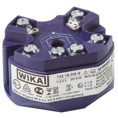
Цифровий температурний перетворювач
Опис
Ці температурні перетворювачі призначені для універсального застосування в процесній промисловості. Вони забезпечують високу точність, гальванічну розв’язку та відмінний захист від електромагнітних впливів (EMI). Через протокол HART ® температурні перетворювачі T32 можна налаштовувати (забезпечувати сумісність) за допомогою різноманітних відкритих інструментів конфігурації. Окрім різних типів датчиків, наприклад датчиків відповідно до DIN EN 60751, JIS C1606, DIN 43760, IEC 60584 або DIN 43710, також можна визначати характеристики датчиків, задані замовником, шляхом введення пар значень (лінійна апроксимація, визначена користувачем).
Завдяки конфігурації датчика з резервуванням (подвійний датчик) у разі відмови датчика він автоматично перемикається на робочий датчик. Крім того, є можливість активувати виявлення дрейфу датчика. У цьому разі сигналізація про помилку виникає, коли величина різниці температур між датчиком 1 і датчиком 2 перевищує значення, яке можна вибрати користувачем.
Для отримання додаткових допусків див. стор. 8
Рис. ліворуч: виконання з монтажем на головку, модель T32.1S Рис. праворуч: виконання для монтажу на DIN-рейку, модель T32.3S
Перетворювач T32 також має додаткові складні функції контролю, такі як моніторинг опору з’єднувальних проводів датчика та контроль обриву датчика відповідно до NAMUR NE89, а також моніторинг діапазону вимірювання. Крім того, ці перетворювачі мають комплексну циклічну функцію самоконтролю.
Габарити перетворювача з монтажем на головку відповідають формі B DIN з’єднувальних головок із розширеним монтажним простором, наприклад WIKA модель BSS.
Перетворювачі в корпусах для монтажу на рейку придатні для всіх стандартних рейок відповідно до IEC 60715. Перетворювачі постачаються з базовою конфігурацією або налаштовані відповідно до вимог замовника.
Особливості
- SIL-версія, сертифікована TÜV, для захисних систем, розроблених за IEC 61508 (опція)
- Застосування в системах безпеки до SIL 2 (одиночний прилад) та SIL 3 (резервована конфігурація)
- Налаштування майже за допомогою всіх програмних та апаратних засобів
- Універсальність для підключення 1 або 2 сенсорів: термометр опору, резистивний сенсор, термопара, mV-сенсор, потенціометр
- Термометр опору, датчик опору
- Термопара, датчик мВ
- Потенціометр
- Сигналізація відповідно до NAMUR NE43, виявлення обриву сенсора відповідно до NE89, ЕМС відповідно до NE21
Питання та відповіді
Який діапазон вимірювання температури підтримує перетворювач?
Залежно від типу датчика підтримуються діапазони, наприклад -200 … +850 °C для термометрів опору та до +1768 °C для термопар типу R/S. Повний перелік діапазонів наведено в даташиті ds_te3204_en_co_cf6f79.
Яка точність вимірювання?
Точність становить ±0,03 % діапазону вимірювання.
Які датчики можна підключати?
Термометри опору Pt100, Pt(x), JPt100, Ni100, термопари типів J, K, L, E, N, T, U, R, S, B, а також mV-датчики та потенціометри. Можливе підключення одного або двох датчиків із резервуванням.
Який вихідний сигнал і протокол зв'язку?
Вихідний аналоговий сигнал 4 … 20 mA з цифровим протоколом HART®; конфігурування можливе майже всіма стандартними програмними та апаратними інструментами.
У якому температурному діапазоні працює прилад?
Температура навколишнього середовища: -60 … +85 °C.
Який ступінь захисту корпусу?
Ступінь захисту IP65.
Чи є вибухозахищене виконання?
Так, є виконання ATEX та IECEx, зокрема II 1G Ex ia IIC і II 3G Ex ic IIC T4/T5/T6 Gc.
Чим ця модель відрізняється від сусідніх у серії T32?
Модель T32.1S — це виконання для монтажу на головку (форма B DIN); серія також включає версію T32.3S для монтажу на DIN-рейку. Опційно доступна сертифікована TÜV SIL-версія для захисних систем за IEC 61508.
| Модель | T32.1S |
| Сімейство | T32 |
| Підтип | head-mounted version |
| Діапазон температури | −270…+1300 °C · −200…+850 °C · −50…+1768 °C · −200…+500 °C · −60…+250 °C · −210…+1200 °C · −200…+900 °C · −270…+1000 °C · −270…+400 °C · −200…+600 °C · +0…+1820 °C |
| Клас точності | ±0.03 % of measuring span |
| Рівень функціональної безпеки (SIL) | SIL 2 (single instrument), SIL 3 (redundant configuration) |
| Вихідний сигнал | HART · 4-20mA |
| Живлення | DC 10.5 ... 42 V |
| Електр. приєднання | Terminals 1-4 |
| Темп. навколишнього середовища | −60…+85 °C |
| Ступінь захисту IP | IP65 |
| Вага | 0.07 kg |
| Сертифікати | CERoHSEACREACHNAMUR |
| Вибухозахист | II 3G Ex ic IIC T4/T5/T6 GcRU C-DE.ГБ08.B.02485, intrinsically safe equipment 0 Ex ia IIC T4/T5/T6 1 Ex ib IIC T4/T5/T6 2 Ex ic IIC T4/T5/T6 DIP A20 Ta 120 °C DIP A21 Ta 120 °CII 1G Ex ia IICATEXIECEx |
| Тип сенсора | Pt100, Pt(x), JPt100, Ni100, thermocouple types J, K, L, E, N, T, U, R, S, B, mV sensor, potentiometer |
| Мови datasheet | EN, DE |
| Sensor type | Max. configurable measuring range | Standard | Min. measuring span (MS) 1) | |
|---|---|---|---|---|
| Resistance sensor | Pt100 | -200 ...+850 °C [-328 ... +1,562 °F] | IEC 60751 | 10 K |
| Pt (x) 2) 10 ... 1000 | -200 ...+850 °C [-328 ... +1.562 °F] | IEC 60751 | ||
| JPt100 | -200 ...+500 °C [-328 ...+932 °F] | JIS C1606:1989 | ||
| Ni100 | -60 ...+250 °C [-76 ...+482 °F] | DIN 43760:1987 | ||
| Resistance sensor 3) | 0 ...8,370Ω | n.a. | 4Ω | |
| Potentiometer 4) | Potentiometer 3) | 0 ...100% | n.a. | 10% |
| Thermocouple type | J | -210 ... +1,200 °C [-346 ... +2,192 °F] | IEC 60584-1 | 50 K |
| K | -270 ... +1,300 °C [-454 ... +2,372 °F] | IEC 60584-1 | ||
| L (DIN) | -200 ...+900 °C [-328 ... +1,652 °F] | DIN 43710:1985 | ||
| E | -270 ... +1,000 °C [-454 ... +1,832 °F] | IEC 60584-1 | ||
| N | -270 ... +1,300 °C [-454 ...+ 2,372 °F] | IEC 60584-1 | ||
| T | -270 ...+400 °C [-454 ...+752 °F] | IEC 60584-1 | ||
| U | -200 ...+600 °C [-328 ... +1,112 °F] | DIN 43710:1985 | ||
| R | -50 ... +1,768 °C [-58 ... +3,214 °F] | IEC 60584-1 | 150 K | |
| S | -50 ... +1,768 °C [-58 ... +3,214 °F] | IEC 60584-1 | ||
| B | 0 ... 1,820 °C [32 ... 3,308 °F] | IEC 60584-1 | 200 K | |
| Voltage sensor | mVsensor 3) | -500 ...+1,800mV | - | 4mV |
| Measuring current during measurement | Max. 0.3 mA(Pt100) |
|---|---|
| Connection methods | |
| Resistance thermometer (RTD) | 1 sensor in 2-/4-/3-wire connection or 2 sensors in 2-wire connection →for further information, see 'Designation of connection terminals' |
| Thermocouples (TC) | 1 sensor or 2 sensors →for further information, see 'Designation of connection terminals' |
| Max. lead resistance | |
| Resistance thermometer (RTD) | 50 Ωeach wire, 3-/4-wire |
| Thermocouples (TC) | 5 kΩ each wire |
| Cold junction compensation, configurable | Internal compensation or external with Pt100, with thermostat or switched off |
| Input + output in accordance with DIN EN 60770 | ||||
|---|---|---|---|---|
| Input sensor type | Mean temperature coefficient (TC) for each 10 K change in ambient temperature in the range -40 ... +85 °C 1) | Measuring deviation at reference conditions in accordance with DIN EN 60770, NE 145, valid at 23 °C±3K | Lead resistance effects | Long-term stability after 1 year |
| Pt100 2) / JPt100 / Ni100 | ±(0.06 K + 0.015%MV) | -200 °C ≤ MV≤200 °C: ±0.10 K MV>200 °C: ±(0.1 K + 0.01 %|MV - 200 K|) 3) | 4-wire: no effect (0 ... 50 Ωper wire) | ±60 mΩor 0.05% of MV, greater va- lue applies |
| Resistance sensor 5) | ±(0.01 Ω+0.01%MV) | ≤ 890 Ω: 0.053Ω 6) or 0.015%MV 7) ≤ 2,140 Ω: 0.128Ω 6) or 0.015%MV 7) ≤ 4,390 Ω: 0.263Ω 6) or 0.015%MV 7) ≤ 8,380 Ω: 0.503Ω 6) or 0.015%MV 7) | 3-wire: ±0.02 Ω/ 10Ω (0 ... 50 Ωper wire) 2-wire: Resistance of the connection leads 4) | |
| Potentiometer 5) | ±(0.1%MV) | R part /R total is max.±0.5% | - | ±20 µV or 0.05% of MV, greater value applies |
| Thermocouples | ||||
| Type J (Fe-CuNi) | MV>-150 °C: ±(0.07 K + 0.02 %|MV|) | -150 °C < MV<0°C: ±(0.3 K + 0.2 %|MV|) MV>0°C: ±(0.3 K + 0.03%MV) | 6 µV / 1,000Ω 8) | ±20 µV or 0.05% of MV, greater value applies |
| Type K (NiCr-Ni) | -150 °C < MV<1,300 °C: ±(0.1 K + 0.02 %|MV|) | -150 °C < MV<0°C: ±(0.4 K + 0.2 %|MV|) 0 °C < MV < 1,300 °C: ±(0.4 K + 0.04%MV) | 6 µV / 1,000Ω 8) | ±20 µV or 0.05% of MV, greater value applies |
| Type L (Fe-CuNi) | -150 °C < MV<0°C: ±(0.07 K + 0.02 %|MV|) MV>0°C: ±(0.07 K + 0.015%MV) | -150 °C < MV<0°C: ±(0.3 K + 0.1 %|MV|) MV>0°C: ±(0.3 K + 0.03%MV) | 6 µV / 1,000Ω 8) | ±20 µV or 0.05% of MV, greater value applies |
| Type E (NiCr-Cu) | MV>-150 °C: ±(0.1 K + 0.015 %|MV|) | -150 °C < MV<0°C: ±(0.3 K + 0.2 %|MV|) MV>0°C: ±(0.3 K + 0.03%MV) | 6 µV / 1,000Ω 8) | ±20 µV or 0.05% of MV, greater value applies |
| Type N (NiCrSi-NiSi) | -150 °C < MV<0°C: ±(0.1 K + 0.05 %|MV|) MV>0°C: ±(0.1 K + 0.02%MV) | -150 °C < MV<0°C: ±(0.5 K + 0.2 %|MV|) MV>0°C: ±(0.5 K + 0.03%MV) | 6 µV / 1,000Ω 8) | ±20 µV or 0.05% of MV, greater value applies |
| TypeT (Cu-CuNi) | -150 °C < MV<0°C: ±(0.07 K + 0.04%MV) MV>0°C: ±(0.07 K + 0.01%MV) | -150 °C < MV<0°C: ±(0.4 K + 0.2 %|MV|) MV>0°C: ±(0.4 K + 0.01%MV) | 6 µV / 1,000Ω 8) | ±20 µV or 0.05% of MV, greater value applies |
| Type U (Cu-CuNi) | -150 °C < MV<0°C: ±(0.07 K + 0.04%MV) MV>0°C: ±(0.07 K + 0.01%MV) | -150 °C < MV<0°C: ±(0.4 K + 0.2 %|MV|) MV>0°C: ±(0.4 K + 0.01%MV) | 6 µV / 1,000Ω 8) | ±20 µV or 0.05% of MV, greater value applies |
| Type R (PtRh-Pt) | 50 °C < MV<1,600 °C: ±(0.3 K + 0.01 %|MV - 400 K|) | 50 °C < MV<400 °C: ±(1.45 K + 0.12 %|MV - 400 K|) 400 °C < MV<1,600 °C: ±(1.45 K + 0.01 %|MV - 400 K|) | 6 µV / 1,000Ω 8) | ±20 µV or 0.05% of MV, greater value applies |
| Type S (PtRh-Pt) | 50 °C < MV<1,600 °C: ±(0.3 K + 0.015 %|MV - 400 K|) | 50 °C < MV<400 °C: ±(1.45 K + 0.12 %|MV - 400 K|) 400 °C < MV<1,600 °C: ±(1.45 K + 0.01 %|MV - 400 K|) | 6 µV / 1,000Ω 8) | ±20 µV or 0.05% of MV, greater value applies |
| Input sensor type | Mean temperature coefficient (TC) for each 10 K change in ambient temperature in the range -40 ... +85 °C 1) | Measuring deviation at reference conditions in accordance with DIN EN 60770, NE 145, valid at 23 °C±3K | Lead resistance effects | Long-term stability after 1 year |
|---|---|---|---|---|
| Type B (PtRh-Pt) | 450 °C < MV<1,000 °C: ±(0.4 K + 0.02 %|MV - 1,000 K|) MV>1,000 °C: ±(0.4 K + 0.005 %(MV- 1,000 K)) | 450 °C < MV<1,000 °C: ±(1.7 K + 0.2 %|MV - 1,000 K|) MV>1,000 °C: ±1.7 K | 6 µV / 1,000Ω 8) | ±20 µV or 0.05% of MV, greater value applies |
| mV sensor 5) | 2 μV + 0.02 %|MV| 100 μV + 0.08 %|MV| | ≤ 1,160 mV: 10 μV + 0.03 %|MV| > 1,160 mV: 15 μV + 0.07 %|MV| | 6 µV / 1,000Ω 8) | ±20 µV or 0.05% of MV, greater value applies |
| Cold junction (only with TC) | ±0.1 K | ±0.8 K | - | ±0.2 K |
| Output | ±0.03 %of measuring span | ±0.03 %of measuring span | - | ±0.05 %of span |
Переглянути всі (20)
| Measuring rate (only for single RTD/TC sensors) | Typical, measured value update approx. 6/s |
|---|---|
| Influence of supply voltage | Not measurable |
| Effect of load | Not measurable |
| Input Pt100, MV<200 °C | ±0.100 K |
|---|---|
| Output ±(0.03 %of 150 K) | ±0.045 K |
| TC input ±(0.06 K + 0.015 %of 150 K) | ±0.083 K |
| TC output ±(0.03 %of 150 K) | ±0.045 K |
| Measuring deviation (typical) √input² + output² +TC input ² +TC output ² | ±0.145 K |
| Measuring deviation (maximum) (input + output +TC input +TC output ) | ±0.273 K |
| Input Pt1000, MV<200 °C | ±0.100 K |
|---|---|
| Output ±(0.03 %of 100 K) | ±0.03 K |
| TC input ±(0.06 K + 0.015 %of 100 K) * 2 | ±0.15 K |
| TC output ±(0.03 %of 100 K) * 2 | ±0.06 K |
| Measuring deviation (typical) √input² + output² +TC input ² +TC output ² | ±0.19 K |
| Measuring deviation (maximum) (input + output +TC input +TC output ) | ±0.34 K |
| Input type K, 0 °C < MV<1,300 °C ±(0.4 K + 0.04 %of 400 K) | ±0.56 K |
|---|---|
| Cold junction ±0.8 K | ±0.80 K |
| Output ±(0.03 %of 400 K) | ±0.12 K |
| Measuring deviation (typical) √input² + cold junction² + output² | ±0.98 K |
| Measuring deviation (maximum) (input + cold junction + output) | ±1.48 K |
| Output signal | |
|---|---|
| Analogue output (configurable) | ■ 4 ... 20 mA, 2-wire ■ 20 ... 4 mA, 2-wire |
| Temperature linearity | For RTD Linear to temperature per IEC 60751, JIS C1606, DIN 43760 ForTC Linear to temperature per IEC 60584, DIN 43710 |
| Load R A | The permissible load depends on the loop supply voltage. |
| With HART ® | R A ≤ (U B - 11.5 V) / 0.023 A with R A in Ωand U B inV |
| Without HART ® | R A ≤ (U B - 10.5 V) / 0.023 A with R A in Ωand U B inV |
| Load diagram (without HART ® ) | Voltage U B inV Load R A inΩ 11289130.02 Ex ia/ic |
| Output limits (configurable) | |
| In accordance with NAMUR NE43 | Lower limit 3.8mA Upper limit 20.5mA |
| Customer-specifically adjustable | Lower limit 3.6 ...4.0mA Upper limit 20.0 ...21.5mA |
| Option SIL (model T32.xS.xxx-S) | Lower limit 3.8 ...4.0mA Upper limit 20.0 ...20.5mA |
| Simulation | In simulation mode, independent from input signal, simulation value configurable from 3.5 ...23.0mA |
| Current value for signalling | |
| In accordance with NAMUR NE43 | Downscale < 3.6 mA(3.5 mA) Upscale > 21.0 mA(21.5 mA) |
| Setting range | Downscale 3.5 ...3.6mA Upscale 21.0 ...22.5mA |
| PV, primary value (digital HART ® measured value) | Signalling on sensor and hardware error through default value |
| Dampening (configurable) | Configurable between 1 ... 60 s (0 = disabled) |
| Factory configuration | |
| Sensor | 1 sensor |
| Connection method | 3-wire connection |
| Measuring range | 0 ... 150 °C |
| Dampening | Disabled |
| Output limits | Lower limit 3.8mA |
| Current value for signalling | Downscale < 3.6 mA(3.5 mA) |
| Communication | |
| Communication protocol | HART ® protocol rev. 5 1) including burst mode, multidrop →for further information, see page 14 |
| Configuration software | WIKA_T32 | ||
|---|---|---|---|
| →free download from www.wika.com | |||
| Configuration | →For connection example, see page 15 | ||
| User linearisation | Store customer-specific sensor characteristics in the transmitter using software (other sensor types can be used in this way) Number of data points: min. 2 / max. 30 | ||
| Sensor functionality when 2 sensors have been connected (dual sensor) | Transmitter can be configured below these limit values.This is not recommended due to loss of accuracy. | ||
| Sensor 1, sensor 2 redundant | The 4 …20mAoutput signal delivers the process value of sensor 1. If sensor 1 fails, the process value of sensor 2 is output (sensor 2 is redundant). | ||
| Mean value | The 4 ... 20 mAoutput signal delivers the mean value of the two values from sensor 1 and sensor 2. If one sensor fails, the process value of the error-free sensor is output. | ||
| Minimum value | The 4 ... 20 mAoutput signal delivers the lower of the two values from sensor 1 and sensor 2. If one sensor fails, the process value of the error-free sensor is output. | ||
| Maximum value | The 4 ... 20 mAoutput signal delivers the higher of the two values from sensor 1 and sensor 2. If one sensor fails, the process value of the error-free sensor is output. | ||
| Difference 2) | The 4 ... 20 mAoutput signal delivers the difference between sensor 1 and sensor 2. If one sensor fails, an error signalling will be activated. | ||
| Monitoring functions | |||
| Test current for sensor monitoring 3) | Nom.20 µA during test cycle, | otherwise 0 µA | |
| Monitoring NAMUR NE89 (monitoring lead resistance) | Resistance thermometer (Pt100, 4-wire) | R L1 + R L4 > 100 Ωwith hysteresis5Ω R L2 + R L3 > 100 Ωwith hysteresis5Ω | |
| Thermocouple | R L1 +R L4 +R thermocouple > 10 kΩ with hysteresis 100Ω | ||
| 3-wire | Monitoring of the resistance difference between lead 3 and 4; an error will be indicated if there is a difference of > 0.5 Ωbetween leads 3 and 4 | ||
| Sensor break monitoring | Always active | ||
| Sensor short circuit monitoring | Active (only for resistance thermometers) | ||
| Self-monitoring | Active permanently, e.g.RAM/ROM test, logical program operating checks and validity | ||
| Measuring range monitoring | Monitoring of the set measuring range for upper/lower deviations Standard: deactivated | ||
| Monitoring functionality by connection of 2 sensors (dual sensor) | Redundancy | In the case of a sensor error (sensor break, lead resistance too high or outside the measuring range of the sensor) of one of the two sensors, the process value will be only based on the error-free sensor.Once the error is rectified, the process value will again be based on the two sensors, or on sensor 1. | |
| Ageing control (sensor drift monitoring) | An error signalling on the output is activated if the value of the temperature difference between sensor 1 and sensor 2 is higher than a set value, which can be selected by the user.This monitoring only generates a signal if two valid sensor values can be determined and the temperature difference is higher than the selected limit value. (Cannot be selected for the 'Difference' sensor function, since the output signal already indicates the difference value). | ||
| Voltage supply | |||
| Supply voltage U B | DC 10.5 ...42V 4) Attention: Restricted auxiliary power ranges for explosion-protected versions (see |
| Time response | |
|---|---|
| Rise time t 90 | Approx. 0.8 s |
| Switch-on time (time to get the first measured value) | Max. 15 s |
| Warm-up time | After approx. 5 minutes the instrument will function to the specifications (accuracy) given in the data sheet |
| Wire cross-section | ||
|---|---|---|
| T32.1S head-mounted version | Solid wire | 0.14 ... 2.5 mm² (24 ... 14 AWG) |
| Strand with end splice | 0.14 ... 1.5 mm² (24 ... 16 AWG) | |
| T32.3S rail-mounted version | Solid wire | 0.14 ... 2.5 mm² (24 ... 14 AWG) |
| Strand with end splice | 0.14 ... 2.5 mm² (24 ... 14 AWG) | |
| Lead resistance | ||
| With resistance sensors | 50 Ωeach wire, 3-/4-wire | |
| With thermocouples | 5 kΩ each wire | |
| Insulation voltage (input to analogue output) | AC 1,200 V, (50 Hz/60 Hz); 1 | s |
| Non-wetted parts | |
|---|---|
| T32.1S head-mounted version | Plastic, PBT, glass-fibre reinforced |
| T32.3S rail-mounted version | Plastic |
| Ambient temperature | -60 1) / -50 2) / -40 ...+85 °C |
|---|---|
| Storage temperature | -60 1) / -50 2) / -40 ...+85 °C |
| Relative humidity, condensation | |
| T32.1S head-mounted version (in accordance with IEC 60068-2-38: 1974) | Test max. temperature variation 65 °C and -10 °C, 93 %±3%r.h. |
| T32.3S rail-mounted version (in accordance with IEC 60068-2-30: 2005) | Test max. temperature 55 °C, 95 %r.h. |
| Climate class per IEC 654-1: 1993 | Cx (-40 ...+85 °C, 5 ... 95 %r.h.) |
| Salt fog per IEC 60068-2-52 | Severity level 1 |
| Vibration resistance per IEC 60068-2-6:2007 | Test Fc: 10 ... 2,000 Hz; 10 g, amplitude 0.75mm |
| Shock resistance per IEC 68-2-27: 1987 | Test Ea: Acceleration type I 30 g and type II 100 g |
| Free-fall test following IEC 60721-3-2: 1997 | Drop height 1,500mm |
| Ingress protection of the entire instrument (in accordance with IEC/EN 60529) | |
| T32.1S head-mounted version | IP00 (electronics completely potted) |
| T32.3S rail-mounted version | IP20 |
| Service life | Max. service life of 20 years (in line with ISO 13849-1) |
| Logo | Description | Country |
|---|---|---|
| EU declaration of conformity EMCdirective 1) EN 61326 emission (group 1, class B) and immunity (industrial application) RoHS directive | European Union |
| Logo | Description | Country |
|---|---|---|
| EU declaration of conformity ATEX directive Hazardous areas | European Union | |
| IECEx Hazardous areas | International | |
| FM Hazardous areas | USA | |
| CSA Hazardous areas | Canada | |
| EAC EMCdirective | Eurasian Economic Community | |
| - | MTSCHS Permission for commissioning | Kazakhstan |
| Logo | Description | Country |
|---|---|---|
| UkrSEPRO Metrology, measurement technology | Ukraine | |
| Uzstandard Metrology, measurement technology | Uzbekistan | |
| INMETRO Hazardous areas | Brazil | |
| NEPSI Hazardous areas | China | |
| KCs - KOSHA Hazardous areas | South Korea |
| Logo | Description |
|---|---|
| SIL IEC 61508 / IEC 6151 | SIL 2 (option) Functional safety |
| - | China RoHS directive |
| NAMUR | NAMUR ■ EMCper NAMUR NE21 ■ Signalling per NAMUR NE43 ■ Sensor break monitoring per NAMUR NE89 |
| Certificates | ■ 2.2 test report ■ 3.1 inspection certificate |
|---|---|
| Calibration | DAkkS calibration certificate |
| Ex marking | BVS 08 ATEX E 019 X BVS 08.0018X (IECEx certificate) | |
|---|---|---|
| T32.1S head-mounted version | Zones 0, 1 | II 1G Ex ia IIC T4/T5/T6 Ga |
| Zones 20, 21 | II 1D Ex ia IIIC T135 °C Da | |
| T32.3S rail-mounted version | Zones 0, 1 | II 2(1)G Ex ia [ia Ga] IIC T4/T5/T6 Gb |
| Zones 20, 21 | II 2(1)D Ex ia [ia Da] IIIC T135 °C Db | |
| Connection values / Intrinsically safe supply and signal circuit (4 ... 20 mA current loop) | ||
| Terminals | + / - | |
| Supply voltage U B 1) | DC 10.5 ...30V | |
| Maximum voltage U i | DC 30V | |
| Maximum current I i | 130mA | |
| Maximum power P i (gas) | 800mW | |
| Maximum power P i (dust) | 750/650/550mW | |
| Effective internal capacitance C i | 7.8 nF | |
| Effective internal inductance L i | Negligible | |
| Sensor circuit connection values | ||
| Terminals | 1 - 4 | |
| Maximum voltage U 0 | DC 6.5V | |
| Maximum current I 0 | 9.3mA | |
| Maximum power P 0 | 15.2mW | |
| Effective internal capacitance C i | 208 nF | |
| Effective internal inductance L i | Negligible | |
| Maximum external capacitance C 0 | Gas, category 1 and 2, group IIC | 24 µF 2) |
| Gas, category 1 and 2, group IIA | 1,000 µF 2) | |
| Maximum external inductance L 0 | Gas, category 1 and 2, group IIC | 365mH |
| Gas, category 1 and 2, group IIA | 3,288mH | |
| Category 1 and 2, gas IIB, dust IIIC | 1,644mH | |
| Maximum inductance/resistance ratio L 0 /R 0 | Gas, category 1 and 2, group IIC | 1.44 mH/Ω |
| Gas, category 1 and 2, group IIA | 11.5 µH/Ω | |
| Category 1 and 2, gas IIB, dust IIIC | 5.75 mH/Ω | |
| Characteristic curve | Linear |
Не знайшли відповіді у документації? Інженер відповість впродовж робочого дня.
Запитати інженера →1 стандартних артикулів сімейства T32
Якщо знаєте код — оберіть напряму. Якщо ні — користуйтесь конфігуратором у режимі «01».