
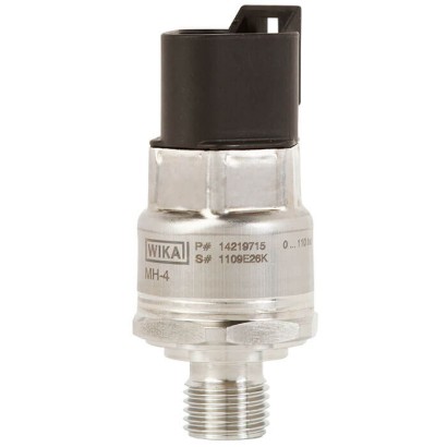
OEM датчик тиску
Опис
Модель MH-4 — це потужний, надійний і надзвичайно стійкий до впливів датчик тиску для мобільних робочих машин. Навіть за складних умов датчик без технічного обслуговування стабільно забезпечує точні вимірювальні дані та гарантує високу експлуатаційну безпеку. Таким чином, це ідеальний вибір для OEM-застосувань.
Особливості
- Розроблено для екстремальних умов експлуатації в мобільних робочих машинах
- Надійність та найвища точність протягом усього життєвого циклу
- Замовницькі адаптації та індивідуалізація
- Великі виробничі потужності
Питання та відповіді
Які діапазони вимірювання доступні для MH-4?
Датчик пропонується з діапазонами від 0 … 6 bar до 0 … 1000 bar, а також у фунтах на квадратний дюйм від 0 … 100 psi до 0 … 10000 psi.
Яка точність датчика MH-4?
Точність становить ≤ ±0,25 % діапазону (BFSL) відповідно до стандарту IEC 62828-1.
Які процесні з'єднання можна обрати?
Доступні різноманітні з'єднання, зокрема M14 x 1.5, O-ring BOSS (7/16-20 UNF, 9/16-18 UNF-2A, 3/4-16 UNF-2A), конус 74° (7/16-20 UNF-2A), NPT (⅛, ¼), метричні та циліндричні різьби G ⅛ B – G ⅜ A/B, а також PT ¼/⅜ і R ¼/⅜.
Для яких середовищ і температур призначений датчик?
Датчик працює за температури середовища та навколишнього середовища від -40 до +125 °C. Деталі, що контактують із середовищем, виготовляються з нержавіючої сталі 304L (1.4307) або PH-сталі, а ущільнення — з NBR, FPM/FKM, міді чи нержавіючої сталі.
Який ступінь захисту має MH-4?
Ступінь захисту — IP67, що забезпечує надійну роботу в брудних і вологих умовах мобільної техніки.
Які вихідні сигнали підтримує датчик?
Аналогові виходи 4 … 20 mA, DC 0 … 5 V, DC 0 … 10 V, DC 1 … 5 V, DC 1 … 10 V та DC 0,5 … 4,5 V за живлення DC 8 … 36 V через круглий роз'єм M12 x 1, код A, 4-контактний.
Чим MH-4 відрізняється від інших датчиків для мобільної техніки?
MH-4 спеціально розроблений для екстремальних умов експлуатації мобільних робочих машин, має типове затвердження KBA та відповідність UN Regulation No. 10, а також допускає адаптацію та індивідуалізацію під конкретного OEM-замовника.
| Модель | MH-4 |
| Підтип | OEM pressure sensor |
| Діапазон тиску | 0…6 bar · 0…10 bar · 0…16 bar · 0…25 bar · 0…40 bar · 0…60 bar · 0…100 bar · 0…160 bar · 0…250 bar · 0…400 bar · 0…600 bar · 0…1000 bar · 0…100 psi · 0…200 psi · 0…300 psi · 0…400 psi · 0…500 psi · 0…1500 psi · 0…2000 psi · 0…3000 psi · 0…5000 psi · 0…8000 psi · 0…10000 psi |
| Клас точності | ≤ ±0.25 % of span (BFSL) |
| Стандарт точності | IEC 62828-1 |
| Технологічне приєднання | M14 x 1.57/16-20 UNF, O-ring BOSS9/16-18 UNF-2A, O-ring BOSS3/4-16 UNF-2A, O-ring BOSS7/16-20 UNF-2A, sealing cone 74°⅛ NPT¼ NPTG ¼ AG ¼ B x 10, form O with collarG ⅜ A, form O with collarPT ¼PT ⅜R ¼R ⅜G ⅛ BG ¼ BG ⅜ BG1/4AG1/4Bx10, form O with collarG3/8A, form O with collar1/8NPT1/4NPTPT1/4PT3/8R1/4R3/8G1/8BG1/4BG3/8B |
| Темп. процесу | −40…+125 °C |
| Вихідний сигнал | 4 ... 20 mA · DC 0 ... 5 V · DC 0 ... 10 V · DC 1 ... 5 V · DC 1 ... 10 V · DC 0.5 ... 4.5 V |
| Живлення | DC 8 ... 36 V |
| Електр. приєднання | Circular connector M12 x 1, code A, 4-pin |
| Матеріал корпусу | Stainless steel 304L (1.4307), glass-fibre reinforced plastic (PBT) |
| Матеріал змочуваних частин | Stainless steel 304L (1.4307), PH grade steel |
| Матеріал ущільнення | NBR, FPM/FKM, Copper, Stainless steel |
| Темп. навколишнього середовища | −40…+125 °C |
| Ступінь захисту IP | IP67 |
| Вага | 0.08 kg |
| Сертифікати | CERoHSEACULUN Regulation No. 10EMC DirectiveComponent approvalType approval by KBAEMC UN Regulation No. 10 |
| Мови datasheet | EN |
| Version | Description |
|---|---|
| MH-4 | OEMpressure sensor |
| MH-4 (E1) | OEMpressure sensor with type approval per UN Regulation No. 10 |
| MH-4 (v) | OEMpressure sensor with pressure compensation element (v = vented) → The pressure compensation element ensures increased accuracy for measuring ranges < 160 bar [< 2,000 psi]. → The pressure compensation element is available for selected electrical connections. → Not suited to applications involving diesel fuels and ambient conditions involving extreme temperature fluctua - tions. |
| Non-linearity per IEC 62828-1 | ≤ ±0.25 %of span (BFSL) 1) 2) |
|---|---|
| Accuracy | → See "Max. measured error per IEC 62828-1" |
| Max. measured error per IEC 62828-1 | ≤ ±1.0 %of span → For measuring ranges < 16 bar, see "Total probable error for measuring ranges ≥ 6 bar ...< 40 bar:" |
| Total probable error per IEC 62828-2 | → See chart "Total probable error" |
| Max. measured error for temperature per IEC 62828-3 | ≤ ±2 K 3) |
| Long-term drift per IEC 62828-1 | ≤ ±0.1 %of span |
| Reference conditions | Per IEC 62828-1 |
| Measuring range | Temperature limit | ||
|---|---|---|---|
| 20 °C [68 °F] 1) | 50 °C [122 °F] | 80 °C [176 °F] | |
| MH-4/MH-4 (E1) | |||
| 0 …6bar | ≤ ±1.7% | ≤ ±3.4% | ≤ ±5.8% |
| 0 …10bar | ≤ ±1.3% | ≤ ±2.3% | ≤ ±3.8% |
| 0 …16bar | ≤ ±1.0% | ≤ ±1.6% | ≤ ±2.7% |
| 0 …25bar | ≤ ±1.0% | ≤ ±1.3% | ≤ ±2.1% |
| MH-4 (v) | |||
| 0 …6bar | ≤ ±1.3% | ≤ ±1.6% | ≤ ±2.2% |
| 0 …10bar | ≤ ±1.0% | ≤ ±1.2% | ≤ ±1.5% |
| 0 …16bar | ≤ ±1.0% | ≤ ±1.0% | ≤ ±1.0% |
| 0 …25bar | ≤ ±1.0% | ≤ ±1.0% | ≤ ±1.0% |
| bar | |
|---|---|
| MH-4/MH-4 (E1) | MH-4 (v) |
| 0 ... 6 | 0 ... 6 |
| 0 ... 10 | 0 ... 10 |
| 0 ... 16 | 0 ... 16 |
| 0 ... 25 | 0 ... 25 |
| 0 ... 40 | 0 ... 40 |
| 0 ... 60 | 0 ... 60 |
| 0 ... 100 | 0 ... 100 |
| 0 ... 160 | - |
| 0 ... 250 | - |
| 0 ... 400 | - |
| 0 ... 600 | - |
| 0 ... 1,000 | - |
Переглянути всі (20)
| Temperature | °C | °F | Temperature steps |
|---|---|---|---|
| Measuring range | -40 ...+125 | -40 ...+257 | - |
| Start of measuring range | -40 ...+0 | -40 ...+32 | In 5 K steps |
| End of measuring range | +85 ...+125 | +185 ...+257 | In 5 K steps |
| Units | ■ bar ■ psi ■ MPa |
|---|---|
| Maximum working pressure | → Corresponds to the upper measuring range value / end value of the measuring range → Any permanent operation above the maximum working pressure is not permissible |
| Overpressure limit per IEC 62828-2 | The overpressure limit is based on the measuring range. Depending on the selected process connection and the seal, restrictions in overpressure limit can result. |
| psi | |
|---|---|
| MH-4/MH-4 (E1) | MH-4 (v) |
| 0 ... 100 | 0 ... 100 |
| 0 ... 200 | 0 ... 200 |
| 0 ... 300 | 0 ... 300 |
| 0 ... 400 | 0 ... 400 |
| 0 ... 500 | 0 ... 500 |
| 0 ... 1,500 | 0 ... 1,500 |
| 0 ... 2,000 | - |
| 0 ... 3,000 | - |
| 0 ... 5,000 | - |
| 0 ... 8,000 | - |
| 0 ... 10,000 | - |
| Measuring ranges ≤ 400 bar [≤ 5,000 psi] | 3 times |
|---|---|
| Measuring ranges > 400 bar and ≤ 600 bar [> 5,000 psi and ≤ 8,000 psi] | 2 times |
| Measuring ranges > 600 bar and ≤ 1,000 bar [> 8,000 psi and ≤ 10,000 psi] | 1.5 times |
| Vacuum resistance | Yes |
| Standard | Thread size | Max. measuring range | Overpressure limit | Seal |
|---|---|---|---|---|
| DIN EN ISO 1179-2 | G¼A | 600 bar [8,000 psi] | 858 bar [12,400 psi] | ■ NBR ■ FPM/FKM |
| DIN EN ISO 9974-2 | M14 x 1.5 | 600 bar [8,000 psi] | 858 bar [12,400 psi] | |
| ISO 6149-2 | M14 x 1.5 | 600 bar [8,000 psi] | 858 bar [12,400 psi] | |
| JIS B2351-1 | G¼Bx10, form Owith collar | 600 bar [8,000 psi] | 858 bar [12,400 psi] | |
| G⅜A,form Owith collar | 600 bar [8,000 psi] | 858 bar [12,400 psi] | ||
| SAE J514 (compatible with SAE J1926 tapped holes) | 7/16-20 UNF, O-ringBOSS | 600 bar [8,000 psi] | 858 bar [12,400 psi] | |
| 9/16-18 UNF-2A, O-ringBOSS | 600 bar [8,000 psi] | 858 bar [12,400 psi] | ||
| 3/4-16 UNF-2A, O-ringBOSS | 600 bar [8,000 psi] | 858 bar [12,400 psi] | ||
| 7/16-20 UNF-2A, sealing cone 74° | 800 bar [10,000 psi] | 1,144 bar [16,500 psi] | - | |
| ANSI/ASME B1.20.1 | ⅛NPT | 400 bar [5,000 psi] | 572 bar [8,200 psi] | |
| ¼NPT | 1,000 bar [13,000 psi] | 1,480 bar [21,400 psi] | ||
| KS | PT¼ | 1,000 bar [13,000 psi] | 1,480 bar [21,400 psi] | |
| PT⅜ | 1,000 bar [13,000 psi] | 1,480 bar [21,400 psi] | ||
| ISO 7 | R¼ | 1,000 bar [13,000 psi] | 1,480 bar [21,400 psi] | |
| R⅜ | 1,000 bar [13,000 psi] | 1,480 bar [21,400 psi] | ||
| EN 837 | G⅛B | 400 bar [5,000 psi] | 572 bar [8,200 psi] | ■ Copper ■ Stainless steel |
| G¼B | 1,000 bar [13,000 psi] | 1,480 bar [21,400 psi] | ||
| G⅜B | 1,000 bar [13,000 psi] | 1,480 bar [21,400 psi] |
| Max. measuring range | → See table "Process connection" |
|---|---|
| Overpressure limit | → See table "Process connection" |
| Seal | → See table "Process connection" |
| Pressure port diameter | For applications that can lead to pressure spikes, a restrictor with a pressure port of 0.3 mmis available. |
| ■ 2.5mm ■ 0.3 mmwith mounted restrictor |
| Output signal | |
|---|---|
| Signal type | |
| Current (2-wire) | 4 ...20mA |
| → Not available with temperature output | |
| Voltage (3-wire) | ■ DC 0 ...5V ■ DC 0 ...10V ■ DC 1 ...5V ■ DC 1 ...10V |
| ■ DC 0.5 ...4.5V → Not available with temperature output | |
| Ratiometric (3-wire) | DC 0.5 ...4.5V |
| Load Ω | |
| Current (2-wire) | ≤ (auxiliary power -7.8 V) / 0.022 A |
| Voltage (3-wire) | ≥ Max. output voltage /1mA |
| Ratiometric (3-wire) | ≥ 4.5 kΩ |
| Signal damping | ■ Without ■ 2 ms ■ 4 ms ■ 9 ms ■ 18 ms ■ 37 ms ■ 75 ms ■ 150 ms |
| Signal clamping | The range of the output signal can be limited. For this purpose, a lower and an upper signal threshold are defined in the sensor electronics. If the output signal reaches these threshold values, the sensor outputs a defined, constant signal value.Therefore, in operation, unwanted pressure or signal ranges are filtered out. |
| ■ Without ■ With |
| Diagnostic function | Permanent errors in the sensor electronics and temporary system overpressures can be output through defined constant output signals.A permanent error signal signifies a sensor defect and cannot be reset.The temporary error signal is reset as soon as the system pressure once again lies under the error threshold. In the application, one can therefore realise an efficient system diagnosis. | |
|---|---|---|
| ■ Without ■ With | ||
| Voltage supply | ||
| Auxiliary power | Current output (2-wire), 4 ...20mA | DC 8 ...36V |
| Voltage output (3-wire), DC 0 ...5V | DC 8 ...36V | |
| Voltage output (3-wire), DC 0 ...10V | DC 12 ...36V | |
| Voltage output (3-wire), DC 1 ...5V | DC 8 ...36V | |
| Voltage output (3-wire), DC 1 ...10V | DC 12 ...36V | |
| Voltage output (3-wire), DC 0.5 ...4.5V | DC 8 ...36V | |
| Voltage output (3-wire), DC0.5 ... 4.5 V, ratiometric | DC 5V ±10% | |
| → Max. auxiliary power with UL approval | DC 35V | |
| Current supply | Current output (2-wire) | ≤ 25mA |
| Voltage output (3-wire) | ≤ 10mA | |
| Ratiometric output (3-wire) | ≤ 10mA | |
| Overvoltage resistance | Current output (2-wire) | DC 48V |
| Voltage output (3-wire) | DC 48V | |
| Ratiometric output (3-wire) | DC 30V | |
| Dynamic behaviour | ||
| Settling time per IEC 62828-1 | Pressure | ≤ 1 ms |
| Temperature | ≤ 10 min | |
| Switch-on time | < 200 ms | - |
| Electrical connection | ||
|---|---|---|
| Connection type | IP code 1) | Permissible temperature range |
| MH-4/MH-4 (E1) | ||
| Circular connector M12 x 1, code A, 4-pin 2) | IP67 per IEC 60529 | -40 ...+125 °C [-40 ...+257 °F] |
| Deutsch connector DT04-2P, 2-pin | ||
| Deutsch connector DT04-3P, 3-pin | ||
| Deutsch connector DT04-4P, 4-pin 2) | ||
| Delphi connector Metri-Pack series 150, 3-pin | ||
| Cable outlet, IP6K9K, 2- or 3-wire | IP6K9K per ISO 20653 | -40 ...+85 °C [-40 ...+185 °F] |
| AMP Micro Quadlok System connector, code A, 3-pin | IP67 per IEC 60529 | -40 ...+125 °C [-40 ...+257 °F] |
| AMP Superseal connector 1.5, 3-pin | ||
| AMP Seal 16 connector, cone, code A, 3-pin | ||
| AMP Econoseal J Mark II series connector, 3-pin | ||
| VWconnector, code I, 4-pin, 2 rows 2) | ||
| MH-4 (v) | ||
| Circular connector M12 x 1, code A, 4-pin 2) | IP67 per IEC 60529 | -40 ...+125 °C [-40 ...+257 °F] |
| Deutsch connector DT04-3P, 3-pin |
| Connection type | → See table "Electrical connection" |
|---|---|
| Pin assignment | → See table "Pin assignment" |
| Ingress protection (IP code) | → See table "Electrical connection" |
| Short-circuit resistance | S+ vs. U- (P vs.U-,T vs.U- for model MH-4 with additional temperature output signal) |
| Reverse polarity protection | U+ vs. U- |
| Insulation voltage | DC 500V (DC 850V optional) |
| 2-wire | 3-wire | ||
|---|---|---|---|
| U+ | A | A | |
| U- | B | B | |
| S+ | - | C |
| 2-wire | 3-wire | ||
|---|---|---|---|
| U+ | 2 | 2 | |
| U- | 1 | 1 | |
| S+ | - | 4 |
| VW connector, code I, 4-pin, 2 rows | 2-wire | 3-wire | |
|---|---|---|---|
| U+ | 2 | 2 | |
| 4 3 2 1 | U- | 1 | 1 |
| S+ | - | 4 |
| AMP Econoseal J Mark II series connector, 3-pin | 2-wire | 3-wire | |
|---|---|---|---|
| U+ | 1 | 1 | |
| 1 2 3 | U- | 3 | 3 |
| S+ | - | 2 |
| Material (wetted) | Stainless steel 304L (1.4307), PH grade steel |
|---|---|
| Material (in contact with the environment) | Stainless steel 304L (1.4307), electrical connection made of highly resistant glass-fibre reinforced plastic (PBT) |
| Operating conditions | |
|---|---|
| Medium temperature limit 1) | -40 ...+125 °C [-40 ...+257 °F] |
| Ambient temperature limit 1) | -40 ...+125 °C [-40 ...+257 °F] |
| Storage temperature limit | -40 ...+70 °C [-40 ...+158 °F] |
| Humidity per EN 60068-2-78 | 93 %at 55 °C [131 °F] relative humidity |
| Condensation | Non-condensing |
| Pollution degree | 2 |
| Vibration resistance per IEC 60068-2-6 | 40g, 10 ... 2,000 Hz |
| Permanent vibration resistance per IEC 60068-2-6 | 10g, 10 ... 2,000 Hz |
| Shock resistance per IEC 60068-2-27 | 100g, 11 ms |
| Free fall in line with IEC 60068-2-31 | |
| Single instrument | 1 m[3.28 ft] |
| Multiple packaging | 0.5 m[1.64 ft] |
| Ingress protection (IP code) | → See "Electrical connection" |
| Service life | 100 million load cycles |
| EMC | |
| ESD per ISO 10605 | ±8 kV contact discharge, ±15 kV air discharge |
| HF field per ISO 11452-2 | 100 V/m |
| BCI per ISO 11452-4 | 200mA |
| Pulse 1 per ISO 7637-2 2) | Level III |
Не знайшли відповіді у документації? Інженер відповість впродовж робочого дня.
Запитати інженера →