
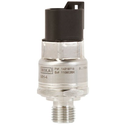
חיישן לחץ OEM
תיאור
הדגם MH-4 הוא חיישן לחץ עוצמתי, אמין ועמיד במיוחד עבור מכונות עבודה ניידות. גם בתנאים תובעניים, החיישן נטול התחזוקה מספק באופן עקבי נתוני מדידה מדויקים ומבטיח רמת בטיחות תפעולית גבוהה. לכן זהו פתרון אידיאלי לשימוש OEM.
תכונות מיוחדות
- פותח לתנאי הפעלה קיצוניים במכונות עבודה ניידות
- אמינות ודיוק מרבי לאורך כל מחזור החיים
- התאמות לפי דרישות הלקוח והתאמה אישית
- כושר ייצור גבוה
שאלות ותשובות
מהו טווח המדידה של ה-MH-4?
החיישן זמין בטווחים מ-0 … 6 bar ועד 0 … 1000 bar, וכן בטווחי psi מ-0 … 100 psi ועד 0 … 10000 psi.
מהי דיוק המדידה?
הדיוק הוא ≤ ±0.25 % of span (BFSL) בהתאם לתקן IEC 62828-1.
אילו אותות פלט זמינים?
החיישן מספק 4 ... 20 mA או אותות מתח: DC 0 ... 5 V, DC 0 ... 10 V, DC 1 ... 5 V, DC 1 ... 10 V ו-DC 0.5 ... 4.5 V, עם אספקת חשמל של DC 8 ... 36 V.
מהו חיבור החשמל?
מחבר עגול M12 x 1, code A, 4-pin.
אילו חיבורי תהליך זמינים?
מגוון רחב של חיבורים, ביניהם M14 x 1.5, 7/16-20 UNF, 9/16-18 UNF-2A, 3/4-16 UNF-2A, ⅛ NPT, ¼ NPT, G ¼ A, G ¼ B x 10, G ⅜ A, PT ¼, PT ⅜, R ¼, R ⅜ ו-G ⅛ B.
מהם חומרי החלקים במגע עם התווך?
Stainless steel 304L (1.4307) או PH grade steel; חומרי האיטום כוללים NBR, FPM/FKM, Copper ו-Stainless steel.
מהו טווח הטמפרטורות המותר?
החיישן מתאים לטמפרטורות סביבה ותווך של -40 … +125 °C, עם דירוג הגנה IP67.
מה מייחד את ה-MH-4 לשימוש OEM?
הוא פותח במיוחד לתנאי ההפעלה הקיצוניים במכונות עבודה ניידות, מציע התאמות לדרישות הלקוח, ומאושר בין היתר לפי UN Regulation No. 10 ו-Type approval by KBA — מה שהופך אותו לפתרון אידיאלי לייצור בנפח גבוה.
| דגם | MH-4 |
| תת-קטגוריה | OEM pressure sensor |
| טווח לחץ | 0…6 bar · 0…10 bar · 0…16 bar · 0…25 bar · 0…40 bar · 0…60 bar · 0…100 bar · 0…160 bar · 0…250 bar · 0…400 bar · 0…600 bar · 0…1000 bar · 0…100 psi · 0…200 psi · 0…300 psi · 0…400 psi · 0…500 psi · 0…1500 psi · 0…2000 psi · 0…3000 psi · 0…5000 psi · 0…8000 psi · 0…10000 psi |
| מחלקת דיוק | ≤ ±0.25 % of span (BFSL) |
| תקן דיוק | IEC 62828-1 |
| חיבור תהליך | M14 x 1.57/16-20 UNF, O-ring BOSS9/16-18 UNF-2A, O-ring BOSS3/4-16 UNF-2A, O-ring BOSS7/16-20 UNF-2A, sealing cone 74°⅛ NPT¼ NPTG ¼ AG ¼ B x 10, form O with collarG ⅜ A, form O with collarPT ¼PT ⅜R ¼R ⅜G ⅛ BG ¼ BG ⅜ BG1/4AG1/4Bx10, form O with collarG3/8A, form O with collar1/8NPT1/4NPTPT1/4PT3/8R1/4R3/8G1/8BG1/4BG3/8B |
| טמפ׳ תהליך | −40…+125 °C |
| אות יציאה | 4 ... 20 mA · DC 0 ... 5 V · DC 0 ... 10 V · DC 1 ... 5 V · DC 1 ... 10 V · DC 0.5 ... 4.5 V |
| הזנה | DC 8 ... 36 V |
| חיבור חשמלי | Circular connector M12 x 1, code A, 4-pin |
| חומר מארז | Stainless steel 304L (1.4307), glass-fibre reinforced plastic (PBT) |
| חומר חלקים רטובים | Stainless steel 304L (1.4307), PH grade steel |
| חומר אטם | NBR, FPM/FKM, Copper, Stainless steel |
| טמפ׳ סביבה | −40…+125 °C |
| דרגת הגנה IP | IP67 |
| משקל | 0.08 kg |
| תקנים | CERoHSEACULUN Regulation No. 10EMC DirectiveComponent approvalType approval by KBAEMC UN Regulation No. 10 |
| שפות גיליון נתונים | EN |
| Version | Description |
|---|---|
| MH-4 | OEMpressure sensor |
| MH-4 (E1) | OEMpressure sensor with type approval per UN Regulation No. 10 |
| MH-4 (v) | OEMpressure sensor with pressure compensation element (v = vented) → The pressure compensation element ensures increased accuracy for measuring ranges < 160 bar [< 2,000 psi]. → The pressure compensation element is available for selected electrical connections. → Not suited to applications involving diesel fuels and ambient conditions involving extreme temperature fluctua - tions. |
| Non-linearity per IEC 62828-1 | ≤ ±0.25 %of span (BFSL) 1) 2) |
|---|---|
| Accuracy | → See "Max. measured error per IEC 62828-1" |
| Max. measured error per IEC 62828-1 | ≤ ±1.0 %of span → For measuring ranges < 16 bar, see "Total probable error for measuring ranges ≥ 6 bar ...< 40 bar:" |
| Total probable error per IEC 62828-2 | → See chart "Total probable error" |
| Max. measured error for temperature per IEC 62828-3 | ≤ ±2 K 3) |
| Long-term drift per IEC 62828-1 | ≤ ±0.1 %of span |
| Reference conditions | Per IEC 62828-1 |
| Measuring range | Temperature limit | ||
|---|---|---|---|
| 20 °C [68 °F] 1) | 50 °C [122 °F] | 80 °C [176 °F] | |
| MH-4/MH-4 (E1) | |||
| 0 …6bar | ≤ ±1.7% | ≤ ±3.4% | ≤ ±5.8% |
| 0 …10bar | ≤ ±1.3% | ≤ ±2.3% | ≤ ±3.8% |
| 0 …16bar | ≤ ±1.0% | ≤ ±1.6% | ≤ ±2.7% |
| 0 …25bar | ≤ ±1.0% | ≤ ±1.3% | ≤ ±2.1% |
| MH-4 (v) | |||
| 0 …6bar | ≤ ±1.3% | ≤ ±1.6% | ≤ ±2.2% |
| 0 …10bar | ≤ ±1.0% | ≤ ±1.2% | ≤ ±1.5% |
| 0 …16bar | ≤ ±1.0% | ≤ ±1.0% | ≤ ±1.0% |
| 0 …25bar | ≤ ±1.0% | ≤ ±1.0% | ≤ ±1.0% |
| bar | |
|---|---|
| MH-4/MH-4 (E1) | MH-4 (v) |
| 0 ... 6 | 0 ... 6 |
| 0 ... 10 | 0 ... 10 |
| 0 ... 16 | 0 ... 16 |
| 0 ... 25 | 0 ... 25 |
| 0 ... 40 | 0 ... 40 |
| 0 ... 60 | 0 ... 60 |
| 0 ... 100 | 0 ... 100 |
| 0 ... 160 | - |
| 0 ... 250 | - |
| 0 ... 400 | - |
| 0 ... 600 | - |
| 0 ... 1,000 | - |
הצגת הכול (20)
| Temperature | °C | °F | Temperature steps |
|---|---|---|---|
| Measuring range | -40 ...+125 | -40 ...+257 | - |
| Start of measuring range | -40 ...+0 | -40 ...+32 | In 5 K steps |
| End of measuring range | +85 ...+125 | +185 ...+257 | In 5 K steps |
| Units | ■ bar ■ psi ■ MPa |
|---|---|
| Maximum working pressure | → Corresponds to the upper measuring range value / end value of the measuring range → Any permanent operation above the maximum working pressure is not permissible |
| Overpressure limit per IEC 62828-2 | The overpressure limit is based on the measuring range. Depending on the selected process connection and the seal, restrictions in overpressure limit can result. |
| psi | |
|---|---|
| MH-4/MH-4 (E1) | MH-4 (v) |
| 0 ... 100 | 0 ... 100 |
| 0 ... 200 | 0 ... 200 |
| 0 ... 300 | 0 ... 300 |
| 0 ... 400 | 0 ... 400 |
| 0 ... 500 | 0 ... 500 |
| 0 ... 1,500 | 0 ... 1,500 |
| 0 ... 2,000 | - |
| 0 ... 3,000 | - |
| 0 ... 5,000 | - |
| 0 ... 8,000 | - |
| 0 ... 10,000 | - |
| Measuring ranges ≤ 400 bar [≤ 5,000 psi] | 3 times |
|---|---|
| Measuring ranges > 400 bar and ≤ 600 bar [> 5,000 psi and ≤ 8,000 psi] | 2 times |
| Measuring ranges > 600 bar and ≤ 1,000 bar [> 8,000 psi and ≤ 10,000 psi] | 1.5 times |
| Vacuum resistance | Yes |
| Standard | Thread size | Max. measuring range | Overpressure limit | Seal |
|---|---|---|---|---|
| DIN EN ISO 1179-2 | G¼A | 600 bar [8,000 psi] | 858 bar [12,400 psi] | ■ NBR ■ FPM/FKM |
| DIN EN ISO 9974-2 | M14 x 1.5 | 600 bar [8,000 psi] | 858 bar [12,400 psi] | |
| ISO 6149-2 | M14 x 1.5 | 600 bar [8,000 psi] | 858 bar [12,400 psi] | |
| JIS B2351-1 | G¼Bx10, form Owith collar | 600 bar [8,000 psi] | 858 bar [12,400 psi] | |
| G⅜A,form Owith collar | 600 bar [8,000 psi] | 858 bar [12,400 psi] | ||
| SAE J514 (compatible with SAE J1926 tapped holes) | 7/16-20 UNF, O-ringBOSS | 600 bar [8,000 psi] | 858 bar [12,400 psi] | |
| 9/16-18 UNF-2A, O-ringBOSS | 600 bar [8,000 psi] | 858 bar [12,400 psi] | ||
| 3/4-16 UNF-2A, O-ringBOSS | 600 bar [8,000 psi] | 858 bar [12,400 psi] | ||
| 7/16-20 UNF-2A, sealing cone 74° | 800 bar [10,000 psi] | 1,144 bar [16,500 psi] | - | |
| ANSI/ASME B1.20.1 | ⅛NPT | 400 bar [5,000 psi] | 572 bar [8,200 psi] | |
| ¼NPT | 1,000 bar [13,000 psi] | 1,480 bar [21,400 psi] | ||
| KS | PT¼ | 1,000 bar [13,000 psi] | 1,480 bar [21,400 psi] | |
| PT⅜ | 1,000 bar [13,000 psi] | 1,480 bar [21,400 psi] | ||
| ISO 7 | R¼ | 1,000 bar [13,000 psi] | 1,480 bar [21,400 psi] | |
| R⅜ | 1,000 bar [13,000 psi] | 1,480 bar [21,400 psi] | ||
| EN 837 | G⅛B | 400 bar [5,000 psi] | 572 bar [8,200 psi] | ■ Copper ■ Stainless steel |
| G¼B | 1,000 bar [13,000 psi] | 1,480 bar [21,400 psi] | ||
| G⅜B | 1,000 bar [13,000 psi] | 1,480 bar [21,400 psi] |
| Max. measuring range | → See table "Process connection" |
|---|---|
| Overpressure limit | → See table "Process connection" |
| Seal | → See table "Process connection" |
| Pressure port diameter | For applications that can lead to pressure spikes, a restrictor with a pressure port of 0.3 mmis available. |
| ■ 2.5mm ■ 0.3 mmwith mounted restrictor |
| Output signal | |
|---|---|
| Signal type | |
| Current (2-wire) | 4 ...20mA |
| → Not available with temperature output | |
| Voltage (3-wire) | ■ DC 0 ...5V ■ DC 0 ...10V ■ DC 1 ...5V ■ DC 1 ...10V |
| ■ DC 0.5 ...4.5V → Not available with temperature output | |
| Ratiometric (3-wire) | DC 0.5 ...4.5V |
| Load Ω | |
| Current (2-wire) | ≤ (auxiliary power -7.8 V) / 0.022 A |
| Voltage (3-wire) | ≥ Max. output voltage /1mA |
| Ratiometric (3-wire) | ≥ 4.5 kΩ |
| Signal damping | ■ Without ■ 2 ms ■ 4 ms ■ 9 ms ■ 18 ms ■ 37 ms ■ 75 ms ■ 150 ms |
| Signal clamping | The range of the output signal can be limited. For this purpose, a lower and an upper signal threshold are defined in the sensor electronics. If the output signal reaches these threshold values, the sensor outputs a defined, constant signal value.Therefore, in operation, unwanted pressure or signal ranges are filtered out. |
| ■ Without ■ With |
| Diagnostic function | Permanent errors in the sensor electronics and temporary system overpressures can be output through defined constant output signals.A permanent error signal signifies a sensor defect and cannot be reset.The temporary error signal is reset as soon as the system pressure once again lies under the error threshold. In the application, one can therefore realise an efficient system diagnosis. | |
|---|---|---|
| ■ Without ■ With | ||
| Voltage supply | ||
| Auxiliary power | Current output (2-wire), 4 ...20mA | DC 8 ...36V |
| Voltage output (3-wire), DC 0 ...5V | DC 8 ...36V | |
| Voltage output (3-wire), DC 0 ...10V | DC 12 ...36V | |
| Voltage output (3-wire), DC 1 ...5V | DC 8 ...36V | |
| Voltage output (3-wire), DC 1 ...10V | DC 12 ...36V | |
| Voltage output (3-wire), DC 0.5 ...4.5V | DC 8 ...36V | |
| Voltage output (3-wire), DC0.5 ... 4.5 V, ratiometric | DC 5V ±10% | |
| → Max. auxiliary power with UL approval | DC 35V | |
| Current supply | Current output (2-wire) | ≤ 25mA |
| Voltage output (3-wire) | ≤ 10mA | |
| Ratiometric output (3-wire) | ≤ 10mA | |
| Overvoltage resistance | Current output (2-wire) | DC 48V |
| Voltage output (3-wire) | DC 48V | |
| Ratiometric output (3-wire) | DC 30V | |
| Dynamic behaviour | ||
| Settling time per IEC 62828-1 | Pressure | ≤ 1 ms |
| Temperature | ≤ 10 min | |
| Switch-on time | < 200 ms | - |
| Electrical connection | ||
|---|---|---|
| Connection type | IP code 1) | Permissible temperature range |
| MH-4/MH-4 (E1) | ||
| Circular connector M12 x 1, code A, 4-pin 2) | IP67 per IEC 60529 | -40 ...+125 °C [-40 ...+257 °F] |
| Deutsch connector DT04-2P, 2-pin | ||
| Deutsch connector DT04-3P, 3-pin | ||
| Deutsch connector DT04-4P, 4-pin 2) | ||
| Delphi connector Metri-Pack series 150, 3-pin | ||
| Cable outlet, IP6K9K, 2- or 3-wire | IP6K9K per ISO 20653 | -40 ...+85 °C [-40 ...+185 °F] |
| AMP Micro Quadlok System connector, code A, 3-pin | IP67 per IEC 60529 | -40 ...+125 °C [-40 ...+257 °F] |
| AMP Superseal connector 1.5, 3-pin | ||
| AMP Seal 16 connector, cone, code A, 3-pin | ||
| AMP Econoseal J Mark II series connector, 3-pin | ||
| VWconnector, code I, 4-pin, 2 rows 2) | ||
| MH-4 (v) | ||
| Circular connector M12 x 1, code A, 4-pin 2) | IP67 per IEC 60529 | -40 ...+125 °C [-40 ...+257 °F] |
| Deutsch connector DT04-3P, 3-pin |
| Connection type | → See table "Electrical connection" |
|---|---|
| Pin assignment | → See table "Pin assignment" |
| Ingress protection (IP code) | → See table "Electrical connection" |
| Short-circuit resistance | S+ vs. U- (P vs.U-,T vs.U- for model MH-4 with additional temperature output signal) |
| Reverse polarity protection | U+ vs. U- |
| Insulation voltage | DC 500V (DC 850V optional) |
| 2-wire | 3-wire | ||
|---|---|---|---|
| U+ | A | A | |
| U- | B | B | |
| S+ | - | C |
| 2-wire | 3-wire | ||
|---|---|---|---|
| U+ | 2 | 2 | |
| U- | 1 | 1 | |
| S+ | - | 4 |
| VW connector, code I, 4-pin, 2 rows | 2-wire | 3-wire | |
|---|---|---|---|
| U+ | 2 | 2 | |
| 4 3 2 1 | U- | 1 | 1 |
| S+ | - | 4 |
| AMP Econoseal J Mark II series connector, 3-pin | 2-wire | 3-wire | |
|---|---|---|---|
| U+ | 1 | 1 | |
| 1 2 3 | U- | 3 | 3 |
| S+ | - | 2 |
| Material (wetted) | Stainless steel 304L (1.4307), PH grade steel |
|---|---|
| Material (in contact with the environment) | Stainless steel 304L (1.4307), electrical connection made of highly resistant glass-fibre reinforced plastic (PBT) |
| Operating conditions | |
|---|---|
| Medium temperature limit 1) | -40 ...+125 °C [-40 ...+257 °F] |
| Ambient temperature limit 1) | -40 ...+125 °C [-40 ...+257 °F] |
| Storage temperature limit | -40 ...+70 °C [-40 ...+158 °F] |
| Humidity per EN 60068-2-78 | 93 %at 55 °C [131 °F] relative humidity |
| Condensation | Non-condensing |
| Pollution degree | 2 |
| Vibration resistance per IEC 60068-2-6 | 40g, 10 ... 2,000 Hz |
| Permanent vibration resistance per IEC 60068-2-6 | 10g, 10 ... 2,000 Hz |
| Shock resistance per IEC 60068-2-27 | 100g, 11 ms |
| Free fall in line with IEC 60068-2-31 | |
| Single instrument | 1 m[3.28 ft] |
| Multiple packaging | 0.5 m[1.64 ft] |
| Ingress protection (IP code) | → See "Electrical connection" |
| Service life | 100 million load cycles |
| EMC | |
| ESD per ISO 10605 | ±8 kV contact discharge, ±15 kV air discharge |
| HF field per ISO 11452-2 | 100 V/m |
| BCI per ISO 11452-4 | 200mA |
| Pulse 1 per ISO 7637-2 2) | Level III |
לא מצאתם תשובה בתיעוד? מהנדס יענה במהלך יום עסקים.
שאלו מהנדס →