
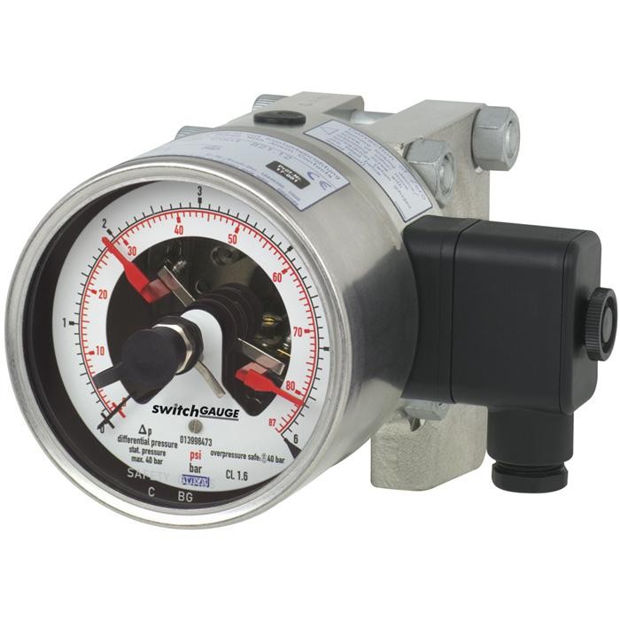
Манометр (датчик) дифференциального давления с контактами переключателя
Описание
Везде, где технологическое давление должно индицироваться локально и при этом требуется переключать электрические цепи, применяется переключающий манометр модели DPGS43HP.1x0 switchGAUGE.
Контакты переключателя (электрические контакты сигнализации) замыкают или размыкают цепи в зависимости от положения стрелки показывающих измерительных приборов. Контакты переключателя регулируются по всей шкале (см. DIN 16085) и устанавливаются преимущественно под циферблатом, хотя частично — и на верхней стороне циферблата. Стрелка прибора (стрелка фактического значения) перемещается свободно по всей шкале, независимо от заданной установки.
Заданная стрелка регулируется с помощью съемного регулировочного ключа через окно.
Особенности
- Высокое рабочее давление (статическое) и высокий запас прочности при перегрузке, выбираемый до 40, 100, 250, 400 или 650 бар [580, 1 450, 3 625, 5 800 или 9 425 psi]
- Гидравлическое демпфирование для защиты от быстрых изменений давления
- Приборы с индуктивными контактами для применения во взрывоопасных зонах
- Приборы с контактным выключателем для применений с ПЛК
- QR-код на шкале ведёт к информации по конкретному прибору
Вопросы и ответы
Какой максимальный статический (рабочий) давление выдерживает прибор?
Перегрузочная стойкость и рабочее давление выбираются при заказе: 40, 100, 250, 400 или 650 бар.
Какие диапазоны измерения перепада давления доступны?
Диапазоны от -1 … 30 бар, а также узкие диапазоны в mbar (например, 0 … 60 mbar), kPa, psi и inHg; полный перечень задаётся при заказе.
Какой класс точности у DPGS43HP.1x0?
Класс точности 1.6 по EN 837-3.
Какие присоединения к процессу предусмотрены?
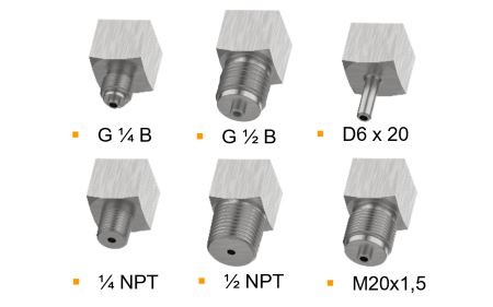
Фланец с дифференциальным присоединением, а также резьбовые варианты: G ½ B (наружная резьба), ½ NPT (наружная резьба) и сдвоенные исполнения 2 x G ½, 2 x G ½ B, 2 x ½ NPT.
Из каких материалов могут быть изготовлены смачиваемые части?
Нержавеющая сталь 316L, Hastelloy C276, Monel 2.4375, Monel 2.4360 или сплав NiCr (Inconel); уплотнение — FPM/FKM. Это позволяет применять прибор в агрессивных средах.
Можно ли использовать прибор во взрывоопасных зонах?
Да, исполнение с индуктивными контактами имеет взрывозащиту ATEX и IECEx: II 2G Ex ia IIC T6/T5/T4 Gb и II 2D Ex ia IIIB T135°C Db.
В каком температурном диапазоне работает прибор?
Температура измеряемой среды: -20 … +100 °C; температура окружающей среды: -20 … +60 °C.
Чем DPGS43HP.1x0 отличается от обычного показывающего дифманометра?
Он сочетает локальную аналоговую индикацию без вспомогательного питания с до трёх коммутируемых контактов (нормально открытый, нормально закрытый, переключающий), что позволяет напрямую сигнализировать и переключать цепи или работать с ПЛК.
Соберите DPGS43HP.1X0 под свою задачу
Артикул собирается автоматически. Если сомневаетесь — напишите инженеру; подскажем по параметрам линии.
- Номинальный размер100
- Переключательконтакт с магнитным поджатием, тип 821
- Действие первого контактазамыкающий (1)
- Действие второго контактабез
- ВзрывозащитаБез
- Электрическое присоединениеразъём сбоку
- Конструкция контактовБез
- Единицы шкалымбар
- Диапазон шкалы0...60 мбар
- Единицы 2-й шкалы или спец. шкалыбез
- Допустимая перегрузка/максимальное рабочее давлениеPN 40 бар
- Присоединение к процессу—
- Материал смачиваемых частейнержавеющая сталь + FPM или нержавеющая сталь + сплав никеля и хрома (Inconel) + FPM
- Расположение присоединениярадиальное
- Гидрозаполнение корпуса—
- Крепежный элемент—
- Фланец для монтажа на панель—
- Дроссельбез
- Конструктивные особенностибез
Завершите конфигурацию
Выберите все параметры, чтобы отправить запрос.
| Модель | DPGS43HP.1x0 |
| Серия | DPGS43HP |
| Подтип | Differential pressure gauge with switch contacts |
| Диапазон давления | 0…0.25 bar · 0…0.4 bar · 0…0.6 bar · 0…1 bar · 0…1.6 bar · 0…2.5 bar · 0…4 bar · 0…6 bar · 0…60 mbar · 0…100 mbar · 0…160 mbar · 0…250 mbar · 0…400 mbar · 0…600 mbar · 0…6 kPa · 0…10 kPa · 0…16 kPa · 0…25 kPa · 0…40 kPa · 0…60 kPa · 0…70 kPa · 0…100 kPa · 0…160 kPa · 0…200 kPa · 0…250 kPa · 0…7 bar · 0…10 bar · 0…14 bar · 0…16 bar · 0…20 bar · 0…25 bar · 0…30 bar · 0…40 bar · 0…1000 mbar · 0…1100 mbar · 0…1200 mbar · 0…1600 mbar · 0…2500 mbar · 0…10 psi · 0…15 psi · 0…30 psi · 0…60 psi · 0…100 psi · 0…150 psi · 0…160 psi · 0…200 psi · 0…250 psi · 0…300 psi · 0…400 psi · 0…500 psi · 0…600 psi · 0…300 kPa · 0…400 kPa · 0…600 kPa · 0…700 kPa · 0…800 kPa · 0…1000 kPa · 0…1400 kPa · 0…1600 kPa · 0…2500 kPa · 0…3000 kPa · 0…4000 kPa · -0.6…0 bar · -1…0 bar · -1…1 bar · -1…1.5 bar · -1…2 bar · -1…3 bar · -1…4 bar · -100…0 kPa · -15…15 kPa · -100…100 kPa · -100…150 kPa · -100…200 kPa · -100…300 kPa · -100…400 kPa · -100…500 kPa · -100…700 kPa · -100…900 kPa · -100…1000 kPa · -100…1500 kPa · -100…2400 kPa · -60…0 mbar · -100…0 mbar · -160…0 mbar · -250…0 mbar · -400…0 mbar · -600…0 mbar · -1000…0 mbar · -1100…0 mbar · -1200…0 mbar · -15…0 inHg · -30…0 inHg · -30…15 inHg · -30…30 inHg · -30…60 inHg · -30…100 inHg · -30…160 inHg · -30…200 inHg · -30…300 inHg · -60…0 kPa · -2…4 kPa · -4…6 kPa · -6…10 kPa · -10…15 kPa · -1…5 bar · -1…7 bar · -1…9 bar · -1…10 bar · -1…15 bar · -1…24 bar · -1…30 bar |
| Класс точности | 1.6 |
| Стандарт точности | EN 837-3 |
| Технологическое присоединение | Flange with differential pressure connectionG ½, female threadG ½ B, male thread½ NPT, male thread2 x G ½, female thread2 x G ½ B, male thread2 x ½ NPT, male thread2xG1/2, female thread2xG1/2B, male thread2x1/2NPT, male thread |
| Темп. процесса | −20…+100 °C |
| Выходной сигнал | Magnetic snap-action contact · Inductive contact · Electronic contact · Reed switch |
| Электр. соединение | Cable socket, black Per VDE 0110 insulation group C/250 V Cable gland M20 x 1.5 |
| Функция переключения | Normally open, Normally closed, Change-over |
| Переключающие контакты | 3 |
| Материал корпуса | Stainless steel 1.4404 (316L), Stainless steel 1.4571 (316Ti), Stainless steel 1.4301 (304) |
| Материал смачиваемых частей | Stainless steel 316L, Hastelloy C276, Monel 2.4375, Monel 2.4360, NiCr alloy (Inconel) |
| Материал уплотнения | FPM/FKM |
| Темп. окружающей среды | −20…+60 °C |
| Степень защиты IP | IP65 |
| Вес | 6.2 kg |
| Сертификаты | CERoHSNACE MR0175/ISO 15156NACE MR0103/ISO 17945EACREACH |
| Взрывозащита | ATEXIECExII 2G Ex ia IIC T6/T5/T4 GbII 2D Ex ia IIIB T135°C DbEx ia IIC T6/T5/T4 GbEx ia IIIB T135°C Db |
| Диаметр шкалы | 100 mm |
| Языки datasheet | EN, DE |
| Accuracy class | ■ 1.6 ■ 2.5 ■ 1.0 (application test required) |
|---|---|
| Zero point setting | |
| Instruments with case filling | External setting |
| Instruments without case filling | Without |
| Influence of static pressure | Depending on scale range and pressure rating →See table 'Influence of static pressure' |
| Temperature error | On deviation from the reference conditions at the measuring system: ≤ ±0.5 %per 10 °C [≤ ±0,5 %per 18 °F] of full scale value |
| Switch hysteresis | Depending on the type of contact used, see from page 6 |
| Reference conditions | |
| Ambient temperature | +20 °C [+68 °F] |
| Span 1) | Measuring deviation relative to the static pressure in %per 10 bar 2) 3) | ||||
|---|---|---|---|---|---|
| PN 40 | PN 100 | PN 250 | PN 400 | PN 650 | |
| 0.06 ... 0.16 bar [0.9 ... 2.3 psi] | ≤ ±0.125 | ≤ ±0.1 | ≤ ±0.12 | - | - |
| 0.25 bar [3.6 psi] | ≤ ±0.125 | ≤ ±0.15 | - | - | - |
| 0.4 bar [5.8 psi] | ≤ ±0.125 | ≤ ±0.1 | ≤ ±0.1 | - | - |
| 0.6 ... 40 bar [8.7 ... 580 psi] | ≤ ±0.125 | ≤ ±0.1 | ≤ ±0.06 | ≤ ±0.063 | ≤ ±0.038 |
| mbar | |
|---|---|
| 0 ... 60 | 0 ... 1,000 |
| 0 ... 100 | 0 ... 1,100 |
| 0 ... 160 | 0 ... 1,200 |
| 0 ... 250 | 0 ... 1,600 |
| 0 ... 400 | 0 ... 2,500 |
| 0 ... 600 | - |
| bar | |
|---|---|
| 0 ... 0.25 | 0 ... 7 |
| 0 ... 0.4 | 0 ... 10 |
| 0 ... 0.6 | 0 ... 14 |
| 0 ... 1 | 0 ... 16 |
| 0 ... 1.6 | 0 ... 20 |
| 0 ... 2.5 | 0 ... 25 |
| 0 ... 4 | 0 ... 30 |
| 0 ... 6 | 0 ... 40 |
Смотреть все (20)
| 0 ... 10 | 0 ... 200 |
|---|---|
| 0 ... 15 | 0 ... 250 |
| 0 ... 30 | 0 ... 300 |
| 0 ... 60 | 0 ... 400 |
| 0 ... 100 | 0 ... 500 |
| 0 ... 150 | 0 ... 600 |
| 0 ... 160 | - |
| kPa | |
|---|---|
| 0 ... 6 | 0 ... 300 |
| 0 ... 10 | 0 ... 400 |
| 0 ... 16 | 0 ... 600 |
| 0 ... 25 | 0 ... 700 |
| 0 ... 40 | 0 ... 800 |
| 0 ... 60 | 0 ... 1,000 |
| 0 ... 70 | 0 ... 1,400 |
| 0 ... 100 | 0 ... 1,600 |
| 0 ... 160 | 0 ... 2,500 |
| 0 ... 200 | 0 ... 3,000 |
| 0 ... 250 | 0 ... 4,000 |
| -60 ... 0 | -10 ...+50 |
|---|---|
| -100 ... 0 | -20 ...+80 |
| -160 ... 0 | -40 ...+120 |
| -250 ... 0 | -50 ...+50 |
| -400 ... 0 | -50 ...+200 |
| -600 ... 0 | -80 ...+80 |
| -1,000 ... 0 | -100 ...+150 |
| -1,100 ... 0 | -200 ...+600 |
| -1,200 ... 0 | -500 ...+500 |
| -0.6 ... 0 | -1 ...+5 |
|---|---|
| -1 ... 0 | -1 ...+7 |
| -1 ...+1 | -1 ...+9 |
| -1 ... +1.5 | -1 ...+10 |
| -1 ...+2 | -1 ...+15 |
| -1 ...+3 | -1 ...+24 |
| -1 ...+4 | -1 ...+30 |
| Unit | ■ mbar ■ bar ■ psi ■ mmH 2 O ■ inH 2 O ■ kg/cm 2 | |
|---|---|---|
| Overload safety and max. operating pressure (static pressure) | ||
| Pressure ratings PN 40 ...PN 400 | Max. 40, 100, 250 or 400 bar [580, 1,450, 3,625 or 5,800 psi] On one, both and alternatingly on the ⊕and ⊖sides | |
| Pressure rating PN 650 | Max. 400 bar [5,800 psi] on one side and alternatingly on the ⊕and ⊖sides Max. 650 bar [9,425 psi] on both sides on the ⊕and ⊖sides | |
| Dial | ||
| Scale layout | ■ Single scale ■ Dual scale | |
| Scale colour | Single scale | Black |
| Dual scale | Black/red | |
| Material | Aluminium | |
| Customer-specific version | ■ Without ■ With special scale, e.g. linear pressure or square root incrementation | |
| → Other scales, e.g. with red mark, circular arcs or circular sectors, on request →Alternatively, adhesive label set for red and green circular arcs; see data sheet AC 08.03 | ||
| Instrument pointer | Aluminium, black | |
| Set pointer | Aluminium, red |
| -60 ... 0 | -100 ...+200 |
|---|---|
| -100 ... 0 | -100 ...+300 |
| -2 ...+4 | -100 ...+400 |
| -4 ...+6 | -100 ...+500 |
| -6 ...+10 | -100 ...+700 |
| -10 ...+15 | -100 ...+900 |
| -15 ...+15 | -100 ... +1,000 |
| -100 ...+100 | -100 ... +1,500 |
| -100 ...+150 | -100 ... +2,400 |
| Output signal | |
|---|---|
| Electronic contact, model 830 E | ■ For direct triggering of a programmable logic controller (PLC) ■ Long service life due to non-contact switching ■ Low influence on the indication accuracy ■ Fail-safe switching at high switching frequency ■ Insensitive to corrosion |
| Reed switch, model 851 | ■ No control unit and no supply voltage required ■ Direct switching up to 250 V, 1 A ■ For direct triggering of a programmable logic controller (PLC) ■ Wear-free, as non-contact |
| Contact setting | ■ Contact(s) adjustable, adjustment key attached to cable socket ■ Contact(s) fixed, without adjustment lock 1) ■ Adjustment lock sealable (tamper-proof) ■ Adjustment lock sealed (tamper-proof) 1) ■ Captive adjustment key with the adjustment lock connected |
| Type of contact | Magnetic snap-action contact |
|---|---|
| Switch technology | ■ No control unit and no supply voltage required ■ Direct switching up to 250 V, 1 A |
| Number of switch contacts | Max. 3 switch contacts With measuring span < 100 mbar, max. 2 switch contacts |
| Switching function | ■ Separate circuits with ≥ 2 switches ■ Cable break monitoring with parallel resistance (47 kΩ or 100 kΩ) |
| The switching function of each switch is indicated by index 1, 2 or 3 | |
| Model 821.1 | Normally open (clockwise pointer motion) |
| Model 821.2 | Normally closed (clockwise pointer motion) |
| Model 821.3 | Change-over; one contact breaks and one contact makes simultaneously when pointer reaches set point |
| Switch point setting | Set pointers of the contact pressure gauges are freely adjustable over the full scale range |
| Setting range (recommended) | 25 ... 75 %of span 1) |
| Distance between switch points | Recommended minimum distance between 2 contacts: 20 %of span |
| Switch hysteresis | 2 ... 5 %(typical) |
| Switching current | 0.02 ... 0.3 A (resistive load) Permissible switch-on and switch-off current: ≤ 0.5 A |
| Switching voltage 1) | AC/DC 24 ...250V |
| Switching power | |
| Instruments without filling | ≤ 30 W, ≤ 50VA |
| Instruments with filling | ≤ 20 W, ≤ 20VA |
| Contact material | Silver-nickel, gold-plated |
| Switching voltage | Instruments without filling | Instruments with filling | ||||
|---|---|---|---|---|---|---|
| Resistive load | Inductive load | Resistive load | Inductive load | |||
| Direct current | Alternating current | cos ϕ>0.7 | Direct current | Alternating current | cos ϕ>0.7 | |
| DC 220 V / AC 230 V | 100mA | 120mA | 65mA | 65mA | 90mA | 40mA |
| DC 110 V / AC 110 V | 200mA | 240mA | 130mA | 130mA | 180mA | 85mA |
| DC 48 V / AC 48 V | 300mA | 450mA | 200mA | 190mA | 330mA | 130mA |
| DC 24 V / AC 24 V | 400mA | 600mA | 250mA | 250mA | 450mA | 150mA |
| Type of contact | Inductive contact |
|---|---|
| Switch technology | ■ Suitable for use in hazardous areas with corresponding control unit (model 904.xx) ■ Long service life due to non-contact switching ■ Low influence on the indication accuracy ■ Fail-safe switching at high switching frequency ■ Insensitive to corrosion |
| Number of switch contacts | Max. 3 switch contacts With measuring span < 100 mbar, max. 2 switch contacts |
| Switching function | Contact versions: ■ 831-N ■ 831-SN, safety version 1) ■ 831-S1N, safety version 1) , inverted signal The switching function of each switch is indicated by index 1 or 2 |
| Model 831.1 | Normally open (clockwise pointer motion) |
| Model 831.2 | Normally closed (clockwise pointer motion) |
| Switch point setting | Set pointers of the contact pressure gauges are freely adjustable over the full scale range |
| Setting range (recommended) | 10 ... 90 %of span 2) |
| Distance between switch points | Up to 2 contacts can be set to an identical set point. For a version with 3 contacts this is not possible.The left (1st contact) or right (3rd contact) contact may not be set to the same set point as the other two contacts.The required displacement is approx. 30°, optionally to the right or to the left. |
| Switching current | Depending on the control unit used, see data sheet AC 08.04 |
| Switching voltage | Depending on the control unit used, see data sheet AC 08.04 |
| Switching power | Depending on the control unit used, see data sheet AC 08.04 |
| Permissible temperature ranges in hazardous areas | |
| T6 | -20 ...+60 °C |
| T4 ...T1 | -20 ...+70 °C |
| T135°C | -20 ...+70 °C |
| Safety-related characteristic values (Ex) 3) | |
| Max. input voltage U i | 16V |
| Max. input current Ii | 25mA |
| Max. input power Pi | 64mW |
| Effective internal capacitance Ci | 30 nF |
| Effective internal inductance Li | 100 µH |
| Model | Version | Ex version |
|---|---|---|
| 904.28 KFU8-SR-Ex1.W | 1 contact | Yes |
| 904.29 KFU8-SR-Ex2.W | 2 contacts | Yes |
| 904.30 KHA6-SH-Ex1 | 1 contact | Yes - Safety version |
| 904.33 KFD2-SH-Ex1 | 1 contact | Yes - Safety version |
| Type of contact | Electronic contact (PNP transistor) |
|---|---|
| Switch technology | ■ For direct triggering of a programmable logic controller (PLC) ■ Long service life due to non-contact switching ■ Low influence on the indication accuracy ■ Fail-safe switching at high switching frequency ■ Insensitive to corrosion |
| Number of switch contacts | Max. 3 switch contacts With measuring span < 100 mbar, max. 2 switch contacts |
| Switching function | Contact versions: ■ 2-wire system ■ 3-wire system |
| The switching function of each switch is indicated by index 1 or 2 | |
| Model 830 E.1 | Normally open (clockwise pointer motion) |
| Model 830 E.2 | Normally closed (clockwise pointer motion) |
| Setting range (recommended) | 10 ... 90 %of span 1) |
| Distance between switch points | Up to 2 contacts can be set to an identical set point. For a version with 3 contacts this is not possible.The left (1st contact) or right (3rd contact) contact may not be set to the same set point as the other two contacts.The required displacement is approx. 30°, optionally to the right or to the left. |
| Switching current | ≤ 100mA |
| Switching voltage | DC 10 ...30V |
| Output signal: Reed switch, model 851 | |
|---|---|
| Type of contact | Bistable reed switch |
| Switch technology | ■ No control unit and no supply voltage required ■ Direct switching up to 250 V, 1 A ■ For direct triggering of a programmable logic controller (PLC) ■ Wear-free, as non-contact |
| Number of switch contacts | |
| NS 100 | Max. 2 switch contacts |
| NS 160 | 1 switch contact |
| Switching function | ■ Separate circuits with ≥ 2 switches ■ Cable break monitoring with parallel resistance (47 kΩ or 100 kΩ) |
| The switching function of this switch is indicated by index 3 | |
| Model 851.3 | 1 x change-over; one contact breaks and one contact makes simultaneously when pointer reaches set point |
| Switch point setting | Set pointers of the contact pressure gauges are freely adjustable within 10 ...90% of span |
| Setting range (recommended) | 10 ... 90 %of span |
| Distance between switch points | When using two contacts, these cannot be set to the same point. Depending on the switching function, a minimum clearance of 15 ... 30° is required. |
| Switch hysteresis | 3 ...5% |
| Switching current | ≤ AC/DC 1 A |
| Switching voltage | ≤ AC/DC 250V |
| Switching power | ≤ 60 W, 60VA |
| Contact material | Rhodium |
| Transport current | AC/DC 2 A |
| Inductive load cosϕ | 1 |
| Contact resistance (static) | 100mΩ |
| Insulation resistance | 10 9 Ω |
| Breakdown voltage | DC 1,000V |
| Switching time incl. contact bounce | 4.5 ms |
| Connection type | ■ Cable socket, black PerVDE 0110 insulation group C/250V Cable gland M20 x 1.5 ■ Connector |
|---|---|
| Wire cross-section | 6 screw terminals + PE for 2.5 mm² |
| Cable diameter | Use cable with a diameter of 7 ... 13 mm[0.276 ... 0.512 in] |
| Pin assignment | The pin assignment is given on the product label of the instrument.The connection and grounding terminals are appropriately marked. |
| Material | PA 6 (polyamide) |
| Medium temperature range | ■ -20 ... 100 °C [-4 ...+212 °F] ■ +200 °C [+392 °F] maximum |
|---|---|
| Ambient temperature range | ■ -20 ...+60 °C [-4 ...+140 °F] |
| Storage temperature range | -20 ...+60 °C [-4 ... 140 °F] |
| Pressure limitation | |
| Steady | Full scale value |
| Fluctuating | 0.9 x full scale value |
| Ingress protection per IEC/EN 60529 | ■ IP54 ■ IP65 1) ■ IP66 (application test required) |
| Description | Region |
|---|---|
| EU declaration of conformity | European Union |
| Pressure Equipment Directive PS > 200 bar, module A, pressure accessory | |
| EMCDirective | |
| LowVoltage Directive | |
| RoHS |
Не нашли ответа в документации? Инженер ответит в течение рабочего дня.
Спросить инженера →122 стандартных артикулов семейства DPGS43HP
Если знаете код — выберите напрямую. Если нет — пользуйтесь конфигуратором в режиме «01».