
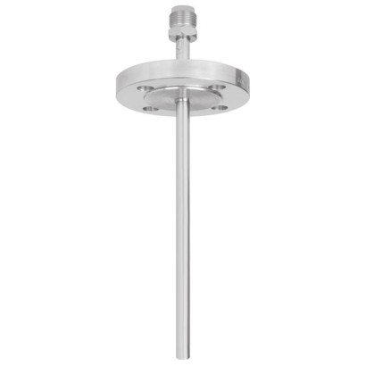
צינור הגנה עם אוגן
תיאור
כל שרוול תרמי/צינור הגנה הוא רכיב חשוב בכל נקודת מדידת טמפרטורה. הוא משמש להפרדת התהליך מהסביבה, ובכך מגן על הסביבה ועל אנשי התפעול, ומונע ממדיה אגרסיבית, לחצים גבוהים וזרימות גבוהות להגיע ישירות לגוף חיישן הטמפרטורה. בכך הוא מאפשר להחליף את המדחום במהלך פעולה.
בהתבסס על אפשרויות היישום כמעט בלתי מוגבלות, קיימים מספר רב של וריאנטים, כגון תכנוני צינור הגנה או חומרי גלם. סוג חיבור התהליך ושיטת הייצור הבסיסית הם קריטריוני בידול תכנוניים חשובים. ניתן לבצע בידול בסיסי בין צינורות הגנה עם הברגה לבין צינורות הגנה להרתכה, וכן בין אלה עם חיבורי אוגן.
בנוסף, ניתן להבחין בין צינורות הגנה לבין שרוולים תרמיים (thermowells). צינורות הגנה בנויים מצינור, אשר בקצהו נסגר באמצעות טיפ מוצק מרותך. שרוולים תרמיים מיוצרים ממוט מלא.
תכונות מיוחדות
- עם ציפוי בעל עמידות גבוהה במיוחד לקורוזיה (דגמים TW40-8, TW40-9)
- יחס מחיר/ביצועים טוב לחומרים מיוחדים
- תכנון בעל תגובה מהירה (דגמים TW40-9, TW40-E)
שאלות ותשובות
לאילו עומסי תהליך מתאים צינור ההגנה TW40?
הדגמים TW40-8 ו-TW40-9 מתאימים לעומסי תהליך נמוכים ובינוניים, בהתאם לתכנון לפי DIN 43772.
אילו חומרים זמינים לצינור ההגנה?
זמינים Stainless steel 1.4571, Alloy C4, Alloy C276, Alloy 400, Titanium grade 2 ו-Tantalum — מה שמאפשר שימוש גם בסביבות בעלות קורוזיה חזקה.
אילו חיבורי תהליך נתמכים?
אוגנים לפי EN 1092-1, DIN 2527 ו-ASME B16.5, וכן הברגות M24 x 1.5, G ½, ½ NPT ו-M20 x 1.5 (כולל גרסאות הברגה נקבה).
מה ההבדל בין הדגמים TW40-8, TW40-9 ו-TW40-E?
TW40-8 ו-TW40-9 מיועדים לציפוי עמיד במיוחד לקורוזיה; TW40-9 ו-TW40-E מציעים תכנון תגובה מהירה.
לאילו תעשיות מיועד ה-TW40?
הוא מיועד לתעשייה הכימית, לטכנולוגיית תהליכים ולייצור ציוד.
מה התקן שלפיו מתוכנן צינור ההגנה?
הגרסה מתוכננת לפי DIN 43772 בטפסים 2F ו-3F.
האם ניתן להחליף את המדחום במהלך הפעולה?
כן — צינור ההגנה מפריד את התהליך מהסביבה ומגן על חיישן הטמפרטורה, ובכך מאפשר החלפת המדחום במהלך פעולה.
הרכיבו TW40 לפי המשימה
המק״ט נבנה אוטומטית. בספק — פנו למהנדס; נסייע לפי פרמטרי הקו.
- Thermowell styleForm 2F (straight)
- MaterialStainless steel 1.4571
- Tube dimensionTube 9x1 mm for sensor 6 mm (DIN 43772)
- Connection to thermometer [N]M24 x 1.5 running nut
- Flange sizeEN 1092-1 DN 25
- Pressure ratingPN 40
- Flange faceEN 1092-1 Form B1
- Insertion length [U1]—
- Total length [L]—
- Certificates—
סיימו את התצורה
בחרו את כל האפשרויות כדי לשלוח בקשה.
| דגם | TW40 |
| תת-קטגוריה | Protection tube with flange |
| חיבור תהליך | Flanges to EN 1092-1Flanges to DIN 2527Flanges to ASME B16.5M24 x 1.5G ½½ NPTM20 x 1.5G½ female thread½NPT female threadM20 x 1.5 female threadG1/21/2 NPT |
| חומר תרמופור | Stainless steel 1.4571, Alloy C4, Alloy C276, Alloy 400, Titanium grade 2, Tantalum |
| משקל | 1.39 kg |
| תרמופור | כן |
| צורת תרמופור | 2F/3F |
| שפות גיליון נתונים | EN, DE |
| Basic information | |
|---|---|
| Protection tube form | ■ Straight ■ Tapered design |
| Design | |
| DesignTW40-8 | Per DIN 43772 form 2F (straight tube) |
| DesignTW40-9 | Per DIN 43772 form 3F (tapered tube) |
| DesignTW40-D | Per DIN 43772 form 2F, special materials |
| DesignTW40-E | Per DIN 43772 form 3F, with tantalum cover |
| Material (wetted) | ■ Stainless steel 1.4571 ■ Alloy C4 ■ Alloy C276 ■ Alloy 400 ■ Titanium grade 2 ■ Tantalum |
| Other materials on request | |
| Coating (only designs TW40-8, TW40-9) | ■ PFA Layer thickness min. 0.4 mm[0.015 in] (standard) or min. 0.6 mm[0.024 in] (special design) ■ ECTFE (Halar ® ) Layer thickness min. 0.6 mm[0.024 in] |
| Process connection | |||
|---|---|---|---|
| Type of process connection | Flanges to valid national or international standards like e.g.EN 1092-1, DIN 2527, ASME B16.5 | ||
| Flange disc (design TW40-E, TW40-D) | ■ Per EN 1092-1 with sealing face form B1 ■ Per DIN 2527 with sealing face form C per DIN 2526 ■ Per ASME B16.5 with sealing face form RF (smooth sealing face with tantalum) | ||
| Connection to thermometer | ■ M24 x 1.5 (rotatable threaded connection, male nut) ■ G½female thread ■ ½NPTfemale thread ■ M20 x 1.5 female thread | ||
| Bore size Ø d 1 | Tube | Inner diameter | For probes |
| DesignTW40-8 | 9 x 1 mm[0.35 x 0.04 in] | 7.0 mm[0.28 in] | 6 mm[0.24 in] |
| 11 x 2 mm[0.43 x 0.08 in] | 7.0 mm[0.28 in] | 6 mm[0.24 in] | |
| 12 x 1.5 mm[0.47 x 0.06 in] | 9.0 mm[0.35 in] | 8 mm[0.31 in] | |
| 12 x 2.5 mm[0.47 x 0.09 in] | 7.0 mm[0.28 in] | 6 mm[0.24 in] | |
| 14 x 2.5 mm[0.55 x 0.10 in] | 9.0 mm[0.35 in] | 8 mm[0.31 in] | |
| 15 x 2 mm[0.59 x 0.08 in] | 11.0 mm[0.43 in] | 10 mm[0.4 in] | |
| DesignTW40-9 | 12 x 2.5 mm[0.47 x 0.09 in] to 9 mm[0.35 in] | 6.1 mm[0.24 in] | 6 mm[0.24 in] |
| DesignTW40-D | 13.7 x 2.2 mm[0.54 x 0.09 in] | 9.3 mm[0.37 in] | 6 mm[0.24 in] or 8 mm[0.31 in] |
| DesignTW40-E | 11 x 2 mm[0.43 x 0.08 in] with tantalum cover | 7.0 mm[0.28 in] | 6 mm[0.24 in] |
| 15 x 3 mm[0.59 x 0.12 in] with tantalum cover | 9.0 mm[0.35 in] | 8 mm[0.31 in] | |
| 12 x 2.5 mm[0.47 x 0.09 in] to 9 mm[0.35 in] with tantalum cover | 6.1 mm[0.24 in] | 6 mm[0.24 in] | |
| Insertion length U 1 | 50 ... 3,500 mm[1.9 ... 137.8 in] |
| length L | Overall | |||
|---|---|---|---|---|
| DesignsTW40-8,TW40-D 1) ,TW40-E 1) | Insertion length U 1 + 80 mm[3.15 in] | |||
| DesignTW40-9 | Insertion length U 1 + 82 mm[3.23 in] | |||
| Suitable stem length l 1 (dial thermometer) | ||||
| Connection design S, 4, 4.1, 5, 6.1, 6.2, 6.3 and 7 | Parallel thread l 1 = L | - 10 mm[0.4 in] or l 1 = U 1 + M- 10 mm[0.4 in] | ||
| Tapered thread l 1 = | U 1 + M- 2 mm[0.08 in] | |||
| Connection design 2 | l 1 = L - 30 mm[1.2 in] or l 1 = U 1 + M- 30 mm[1.2 in] | |||
| Connection design 3 | l 1 = L - 10 mm[0.4 in] or l 1 = U 1 + M- 10 mm[0.4 in] | |||
| Sealing face roughness | Design | AARH in µinch Ra in µm | Rz in µm | |
| ASME B16.5 | Stock finish | 125 ... 250 3.2 ... 6.3 | - | |
| Smooth finish | < 125 < 3.2 | - | ||
| RTJ | < 63 < 1.6 | - | ||
| Groove/tongue | < 125 < 3.2 | - | ||
| EN 1092-1 | Form B1 | - 3.2 ... 12.5 | 12.5 ... 50 | |
| Form B2 | - 0.8 ... 3.2 | 3.2 ... 12.5 | ||
| DIN 2527 | Form C | - - | 40 ... 160 | |
| Form E | - - | < 16 |
| Max. process temperature, process pressure | Depending on: ■ Load diagram DIN 43772 ■ Protection tube design - Dimensions - Material - Coating ■ Process conditions - Flow rate - Density of medium |
|---|---|
| Wake frequency calculation (option) | The calculation in accordance with ASME PTC 19.3 TW-2016 of individual thermowells minimises the risk of dynamic damage that can be caused by the vortex shedding of a Kármán vortex street (Vortex Induced Vibration; VIV). In addition, the static loads due to lateral flow and the process pressure are calculated depending on the temperature. The calculation can be carried out independently using an online tool or as a WIKA engineered service (subject to charges). → For further information, see Technical information IN 00.15 'Wake frequency |
| calculation'. |
הצגת הכול (7)
| Dimensions in mm[in] | Weight in kg [lbs] |
|---|---|
| Ø F 1 x S | Flange DN 25 PN 16 ... 40 U 1 = 225 mm[8.86 in] |
| 9 x 1 [0.35 x 0.04] | 1.39 [3.06] |
| 11 x 2 [0.43 x 0.08] | 1.55 [3.42] |
| 12 x 1,5 [0,47 x 0,06] | 1,61 [3,55] |
| 14 x 2.5 [0.55 x 0.1] | 1.71 [3.77] |
| 12 x 2.5 [0.47 x 0.09] | 1.64 [3.62] |
| 15 x 2 [0.59 x 0.08] | 1.41 [3.11] |
| 9.3 x 2.2 [0.36 x 0.09] | 1.70 [3.75] |
| DN 40 | PN 16 ... 40 | +0.76 kg [+1.68 lbs] |
|---|---|---|
| DN 50 | PN 16 ... 40 | +1.63 kg [+3.59 lbs] |
| 1" | 150 lbs | -0.46 kg [-1.01 lbs] |
| 1" | 300 lbs | +0.04 kg [+0.09 lbs] |
| 1" | 600 lbs | +0.22 kg [+0.49 lbs] |
| 1 ½" | 150 lbs | +0.22 kg [+0.49 lbs] |
| 1 ½" | 300 lbs | +1.34 kg [+2.95 lbs] |
| 1 ½" | 600 lbs | +1.85 kg [+4.08 lbs] |
| Dimensions in mm[in] | Weight DN 25 ...225mm [0.98 ... 8.86 in] | ||
|---|---|---|---|
| Ø F T | Ø F 1 x S | S 1 | |
| 12 x 0.4 [0.47 x 0.02] | 11 x 2 [0.43 x 0.08] | 2.5 [0.1] | 1.65 |
| 16 x 0.4 [0.63 x 0.02] | 15 x 3 [0.59 x 0.12] | 3.5 [0.14] | 1.75 |
| 13 x 0.4 [0.51 x 0.02] | 12 x 2.5 [0.47 x 0.1] | 6 [0.24] | 1.70 |
לא מצאתם תשובה בתיעוד? מהנדס יענה במהלך יום עסקים.
שאלו מהנדס →6 מק״טים סטנדרטיים של משפחת TW40
אם ידוע הקוד — בחרו ישירות. אם לא — השתמשו בתצורה במצב «01».