
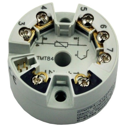
משדר טמפרטורה דיגיטלי, גרסת הרכבה על ראש
תיאור
משדרי הטמפרטורה מדגמים OTMT84 ו-OTMT85 עם תקשורת FOUNDATION™ Fieldbus או PROFIBUS ® PA כוללים כניסה אוניברסלית למדידות טמפרטורה עם מדי טמפרטורה התנגדותיים, צמדים תרמיים, חיישני התנגדות ומקורות מתח, אשר אפשריים עם או בלי ליניאריזציה ייעודית ללקוח. ניתן לבצע מדידות טמפרטורה דיפרנציאליות, ממוצעות או מדידות יתירות.
משדרי הטמפרטורה מאופיינים באמינות, יציבות לטווח ארוך, דיוק גבוה ואפשרויות אבחון מורחבות.
עבור FOUNDATION™ Fieldbus, OTMT85 זמין עם פונקציונליות LAS (Link Active Scheduler) ובקר PID. פונקציונליות זו מאפשרת בקרה ללא תלות במאסטר במכשיר השטח.
ללא אישורים נוספים ראה עמוד 7
תכונות מיוחדות
- Model OTMT84: PROFIBUS® PA profile 3.02
- Model OTMT85: FOUNDATION™ Fieldbus H1
- גרסאות מוגנות מפני פיצוץ Ex ia (בטיחות פנימית/FISCO) ו-Ex ec זמינות
שאלות ותשובות
מה ההבדל בין OTMT84 ל-OTMT85?
OTMT84 מתקשר ב-PROFIBUS® PA (פרופיל 3.02), ואילו OTMT85 מתקשר ב-FOUNDATION™ Fieldbus H1 וזמין עם פונקציונליות LAS ובקר PID לבקרה ללא תלות במאסטר.
אילו חיישני טמפרטורה נתמכים?
Pt100, Pt1000, Ni100, צמדים תרמיים מסוג J, K, L, E, N, T, U, R, S, B, C, D, A, חיישני mV וחיישני התנגדות — עם או בלי ליניאריזציה ייעודית ללקוח.
מה טווח המדידה של המשדר?
הטווח תלוי בחיישן; לדוגמה, עבור צמד תרמי מסוג B: 0 … +2315 °C, ועבור Pt100: -200 … +850 °C.
מהן אפשרויות ההגנה מפני פיצוץ?
זמינה גרסה Ex ia (intrinsically safe/FISCO) עם אישור ATEX PTB 07 ATEX 2056 X ל-Zones 0, 1 (II 1G Ex ia IIC T6...T4 Ga) ואישור IECEx BVS 08.0001X, וכן גרסה Ex ec.
מהו טווח טמפרטורת הסביבה המותר?
-40 … +85 °C.
מהו אות המוצא ואספקת החשמל?
המוצא הוא PROFIBUS® PA או FOUNDATION™ Fieldbus H1, ואספקת החשמל היא DC 9 … 32 V.
מהי דרגת ההגנה מפני חדירה?
IP00 — המשדר מיועד להרכבה בתוך תיבת חיבורים או ראש חיישן מוגן.
מהי דיוק המדידה?
הדיוק מוגדר לפי סטיית המדידה האופיינית לפי DIN EN 60770; יש לעיין בדף הנתונים ds_te8401_en_co_4795e5 לערכים המדויקים.
| דגם | OTMT84 |
| סדרה | OTMT |
| תת-קטגוריה | Fieldbus temperature transmitter |
| טווח טמפרטורה | −50…+1768 °C · +0…+2315 °C · −200…+850 °C · −60…+250 °C · −270…+1372 °C · −260…+400 °C · +40…+1820 °C · +0…+2500 °C · −210…+1200 °C · −200…+900 °C · −270…+1000 °C · −270…+1300 °C · −200…+600 °C |
| מחלקת דיוק | See typical measuring deviation per DIN EN 60770 |
| אות יציאה | PROFIBUS® PA · FOUNDATION™ Fieldbus H1 · PROFIBUS PA · FOUNDATION Fieldbus H1 · FOUNDATION™ Fieldbus |
| הזנה | DC 9 ... 32 V |
| חיבור חשמלי | Screw terminals, ≤ 2.5 mm² (14 AWG) |
| טמפ׳ סביבה | −40…+85 °C |
| דרגת הגנה IP | IP00 |
| משקל | 0.045 kg |
| תקנים | CERoHSNAMUR NE21NAMUR NE89EACREACH |
| הגנת התפוצצות | ATEX: PTB 07 ATEX 2056 X, Zones 0, 1; II 1G Ex ia IIC T6...T4 GaIECEx: BVS 08.0001X, II 1G Ex ia IIC T6...T4 GaEx ia IICT6...T4GaEx ecPTB 07 ATEX 2056 XBVS 08.0001X (IECEx certificate) |
| סוג חיישן | Pt100, Pt1000, Ni100, TC type J, K, L, E, N, T, U, R, S, B, C, D, A, mV sensor, resistance sensor |
| מחלקת חיישן | IEC 60751:2008, JIS C1604:2013, DIN 43760:1987, GOST R8.8585-2001, IEC 60584-1 |
| שפות גיליון נתונים | EN, DE |
| Sensor type | Max. configurable measuring range | Standard | Digital measuring deviation ( ± ) 1) | Non-re- peatability ( ± ) | |
|---|---|---|---|---|---|
| Maximum | Measured value dependent | ||||
| Pt100 | -200 ...+850 °C | IEC 60751: 2008 | ≤ ±0.12 °C | 0.06 °C + 0.006 %x(MV-MRS) | ≤ 0.05 °C |
| JIS C1604: 2013 | ≤ ±0.09 °C | 0.05 °C + 0.006 %x(MV-MRS) | ≤ 0.04 °C | ||
| Pt1000 | -200 ...+850 °C | IEC 60751:2008 | ≤ ±0.09 °C | 0.03 °C + 0.013 %x(MV-MRS) | ≤ 0.05 °C |
| Ni100 | -60 ...+250 °C | DIN 43760: 1987 | ≤ ±0.05 °C | 0.05 °C + 0.006 %x(MV-MRS) | ≤ 0.03 °C |
| Resistance sensor | ■ 10 ...400Ω ■ 10 …2,000Ω | - | ■ 32mΩ ■ 300mΩ | - | ■ 15mΩ ■ ≤ 200mΩ |
| Potentiometer | 0 ...100% | - | 10% | - | ≤ ±0.50% |
| TC type J (Fe-CuNi) | -210 ... +1,200 °C | IEC 60584-1 Cor.1:2015 | ≤ ±0.27 °C | 0.27 °C - 0.005 %x(MV-MRS) | ≤ 0.08 °C |
| TC type K (NiCr-Ni) | -270 ... +1,372 °C | IEC 60584-1 Cor.1:2015 | ≤ ±0.35 °C | 0.35 °C - 0.005 %x(MV-MRS) | ≤ 0.11 °C |
| TC type L (Fe-CuNi) | ■ -200 ...+900 °C ■ -200 ...+800 °C | ■ DIN 43760: 1987 ■ GOST R8.8585-2001 | ■ ≤ ±0.29 °C ■ ≤ ±2.2 °C | ■ 0.29 °C - 0.009 %x(MV-MRS) ■ 2.2 °C - 0.015 %x(MV-MRS) | ■ ≤ 0.07 °C ■ ≤ 0.15 °C |
| TC type E (NiCr-Cu) | -270 ... +1,000 °C | IEC 60584-1: 2014 | ≤ ±0.22 °C | 0.22 °C - 0.006 %x(MV-MRS) | ≤ 0.07 °C |
| TC type N(NiCrSi-NiSi) | -270 ... +1,300 °C | IEC 60584-1: 2014 | ≤ ±0.48 °C | 0.48 °C - 0.014 %x(MV-MRS) | ≤ 0.16 °C |
| TC type T (Cu-CuNi) | -260 ...+400 °C | IEC 60584-1: 2014 | ≤ ±0.36 °C | 0.36 °C - 0.04 %x(MV-MRS) | ≤ 0.11 °C |
| TC type U (Cu-CuNi) | -200 ...+600 °C | - | ≤ ±0.33 °C | 0.33 °C - 0.028 %x(MV-MRS) | ≤ 0.10 °C |
| TC type R (PtRh-Pt) | -50 ... +1,768 °C | IEC 60584-1 Cor.1:2015 | ≤ ±1.12 °C | 1.12 °C - 0.03%xMV | ≤ 0.76 °C |
| TC type S (PtRh-Pt) | -50 ... +1,768 °C | IEC 60584-1: 2014 | ≤ ±1.15 °C | 1.15 °C - 0.022%xMV | ≤ 0.74 °C |
| TC type B (PtRh-Pt) | 40 ... 1,820 °C | IEC 60584-1: 2014 | ≤ ±1.50 °C | 1.5 °C - 0.06 %x(MV-MRS) | ≤ 0.67 °C |
| TC type C (W5Re-W26Re) | 0 ... 2,315 °C | IEC 60584-1: 2014 | ≤ ±0.66 °C | 0.55 °C + 0.0055%xMV | ≤ 0.33 °C |
| TC type D (W3Re-W25Re) | 0 ... 2,315 °C | IEC 60584-1: 2014 | ≤ ±0.75 °C | 0.75 °C - 0.008%xMV | ≤ 0.41 °C |
| TC type A (WRe-WRe) | 0 ... 2,500 °C | IEC 60584-1: 2014 | ≤ ±1.33 °C | 0.8 °C + 0.021%xMV | ≤ 0.52 °C |
| mV sensor | ■ -20 ...100mV ■ -5 ...+30mV | - | 10 µV | - | 4 µV |
| Sensor type | Long-term stability after 1 year (max.) | Ambient temperature: Effect (±) per 1 °C change | Supply voltage: Effect (±) per V change | ||
|---|---|---|---|---|---|
| Maximum (digital 1) ) | Measured value dependent (digital 1) ) | Maximum (digital 1) ) | Measured value dependent (digital 1) ) | ||
| Pt100 | ≤ 0.03 °C + 0.024%x measuring span | ■ ≤ 0.02 °C ■ ≤ 0.01 °C | 0.002 %x(MV-MRS), min. 0.005 °C | ■ ≤ 0.12 °C ■ ≤ 0.01 °C | 0.002 %x(MV-MRS), min. 0.005 °C |
| Pt1000 | ≤ 0.034 °C + 0.02%x measuring span | ≤ 0.01 °C | 0.002 %x(MV-MRS), min. 0.005 °C | ≤ 0.01 °C | 0.002 %x(MV-MRS), min. 0.004 °C |
| Ni100 | ≤ 0.026 °C + 0.015%x measuring span | ≤ 0.05 °C | - | ≤ 0.005 °C | - |
| Resistance sensor | ■ ≤ 10 mΩ+0.022%x measuring span ■ ≤ 144 mΩ+0.009% x measuring span | ■ ≤6mΩ ■ ≤30mΩ | 0.0015 %x(MV-MRS), min.1.5mΩ 0.015 %x(MV-MRS), min.15mΩ | ■ ≤6mΩ ■ ≤30mΩ | ■ 0.0015 %x(MV-MRS), min.1.5mΩ ■ 0.015 %x(MV-MRS), min.15mΩ |
| Potentiometer | - | - | - | - | - |
| TC type J (Fe-CuNi) | ≤ 0.06 °C + 0.019%x measuring span | ≤ 0.02 °C | 0.0028 %x(MV-MRS), min. 0.02 °C | ≤ 0.02 °C | 0.0028 %x(MV-MRS), min. 0.02 °C |
| TC type K (NiCr-Ni) | ≤ 0.09 °C + 0.022%x (MV + 150 °C) | ≤ 0.04 °C | 0.003 %x(MV-MRS), min. 0.013 °C | ≤ 0.04 °C | 0.003 %x(MV-MRS), min. 0.013 °C |
| Sensor type | Long-term stability after 1 year (max.) | Ambient temperature: Effect (±) per 1 °C change | Supply voltage: Effect (±) per V change | ||
|---|---|---|---|---|---|
| Maximum (digital 1) ) | Measured value dependent (digital 1) ) | Maximum (digital 1) ) | Measured value dependent (digital 1) ) | ||
| TC type L (Fe-CuNi) | ■ ≤ 0.06 °C + 0.017% x measuring span ■ ≤ 0.08 °C + 0.015% x measuring span | ≤ 0.02 °C | - | ≤ 0.02 °C | - |
| TC type E (NiCr-Cu) | ≤ 0.06 °C + 0.018%x measuring span | ≤ 0.03 °C | 0.003 %x(MV-MRS), min. 0.016 °C | ≤ 0.03 °C | 0.003 %x(MV-MRS), min. 0.016 °C |
| TC type N(NiCrSi-NiSi) | ≤ 0.13 °C + 0.015%x (MV + 150 °C) | ≤ 0.04 °C | 0.0028 %x(MV-MRS), min. 0.020 °C | ≤ 0.04 °C | 0.0028 %x(MV-MRS), min. 0.020 °C |
| TC type T (Cu-CuNi) | ≤ 0.09 °C + 0.011%x measuring span | ≤ 0.01 °C | - | ≤ 0.01 °C | - |
| TC type U (Cu-CuNi) | ≤ 0.09 °C + 0.013%x measuring span | ≤ 0.01 °C | - | ≤ 0.01 °C | - |
| TC type R (PtRh-Pt) | ≤ 0.31 °C + 0.011%x (MV - 50 °C) | ≤ 0.06 °C | 0.0035 %x(MV-MRS), min. 0.047 °C | ≤ 0.06 °C | 0.0035 %x(MV-MRS), min. 0.047 °C |
| TC type S (PtRh-Pt) | ≤ 0.31 °C + 0.011%x measuring span | ≤ 0.05 °C | - | ≤ 0.05 °C | - |
| TC type B (PtRh-Pt) | ≤ ±0.50 °C | ≤ 0.06 °C | - | ≤ 0.06 °C | - |
| TC type C (W5Re-W26Re) | ≤ 0.15 °C + 0.018%x measuring span | ≤ 0.09 °C | 0.0045 %x(MV-MRS), min. 0.03 °C | ≤ 0.09 °C | 0.0045 %x(MV-MRS), min. 0.03 °C |
| TC type D (W3Re-W25Re) | ≤ 0.21 °C + 0.015%x measuring span | ≤ 0.08 °C | 0.004 %x(MV-MRS), min. 0.035 °C | ≤ 0.08 °C | 0.004 %x(MV-MRS), min. 0.035 °C |
| TC type A (WRe-WRe) | ≤ 0.17 °C + 0.021%x measuring span | ≤ 0.14 °C | 0.0055 %x(MV-MRS), min. 0.03 °C | ≤ 0.14 °C | 0.0055 %x(MV-MRS), min. 0.03 °C |
| mV sensor | ≤ 2 µV + 0.022%x measuring span | ≤ 3 µV | - | ≤ 3 µV | - |
| Measuring current during measurement | Max. 0.3 mA(Pt100) |
|---|---|
| Connection methods | |
| Resistance thermometer (RTD) | 1 sensor in 2-/3-/4-wire connection or 2 sensors in 2-/3-wire connection →For further information, see 'Designation of connection terminals' |
| Thermocouples (TC) | 1 sensor or 2 sensors →For further information, see 'Designation of connection terminals' |
| Max. lead resistance | |
| Resistance thermometer (RTD) | 50 Ωeach wire, 3-/4-wire |
| Thermocouples (TC) | 5 kΩ each wire |
| Cold junction compensation, configurable | Internal cold junction (Pt100) External cold junction:Value adjustable -40 ...+85 °C [-40 ...+185 °F] |
הצגת הכול (20)
| Typical measuring deviation (per DIN EN 60770, 25 °C ±3 °C, supply voltage 24 V DC) | |||
|---|---|---|---|
| Input sensor type | Standard | Measuring range | Typical measuring deviation (±) Digital value 1) |
| Pt100 | IEC 60751: 2008 | 0 ... 200 °C | 0.08 °C |
| Pt1000 | IEC 60751: 2008 | 0 ... 200 °C | 0.08 °C |
| TC type K (NiCr-Ni) | IEC 60584-1 | 0 ... 800 °C | 0.31 °C |
| TC type S (PtRh-Pt) | IEC 60584-1 | 0 ... 800 °C | 0.97 °C |
| TC type L (Fe-CuNi) | GOST R8.8585-2001 | 0 ... 800 °C | 2.18 °C |
| Measuring deviation | 0.084 °C |
|---|---|
| 0.06 °C + 0.006 %x(200 °C - (-200 °C)) |
| Measuring deviation 0.06 °C + 0.006 %x(200 °C - (-200 °C)) | 0.084 °C |
|---|---|
| Influence of ambient temperature (35 - 25) x (0.002 %x200 °C - (-200 °C)) min. 0.005 °C | 0.08 °C |
| Influence of supply voltage (30 - 24) x (0.002 %x200 °C - (-200 °C)) min. 0.005 °C | 0.048 °C |
| Measuring deviation (typical) √(measuring deviation² + influence of ambient temperature² + influence of supply voltage² | 0.126 °C |
| Output signal | |
|---|---|
| Analogue output | ■ FOUNDATION™ Fieldbus ■ PROFIBUS ® PA |
| Version of analogue output | |
| FOUNDATION™ Fieldbus | H1, IEC 61158-2 |
| PROFIBUS ® PA | EN 50170 vol. 2 / profile 3.02 |
| Residual current FDE (Fault Disconnection Electronic) | 0mA |
| Data transfer rate (supported baud rate) | 31.25 kBit/s |
| Signal coding | Manchester |
| Functionality | Basic or LAS |
| Function blocks | |
| FOUNDATION™ Fieldbus | 2 x 3 analogue input (AI) 1 x standard PID controller 1 x input selector (ISEL) |
| PROFIBUS ® PA | 4x analogue input (AI) |
| Execution time, PID controller | < 200 ms |
| Response time (programmable) | 1 ... 60 s |
| Updating time | < 400 ms |
| Execution time, analogue input block | < 50 ms |
| Factory configuration | |
| Sensor | Pt100 |
| Connection method | 3-wire connection |
| Measuring range ('Limit Handling') | 0 ... 100 °C |
| Communication | |
| Communication protocol | Model OTMT84 PROFIBUS ® PA profile 3.02 Model OTMT85 FOUNDATION™ Fieldbus H1 |
| Configuration software | Endress+Hauser FieldCare (DTM) SIMATIC PDM (EDD) |
| Configuration | |
| User linearisation | Store customer-specific sensor characteristics in the transmitter using software (other sensor types can be used in this way) Number of data points: min. 2 / max. 30 |
| Monitoring functions | |
| Test current for sensor monitoring 3) | Nom.20 µA during test cycle, otherwise 0 µA |
| Sensor break monitoring | Always active |
| Sensor short-circuit monitoring | Active (only for resistance thermometers) |
| Self-monitoring | Active permanently, e.g.RAM/ROM test, logical program operating checks and validity check |
| Measuring range monitoring | Monitoring of the set measuring range for upper/lower deviations Standard: Deactivated |
| Output signal | ||
|---|---|---|
| Monitoring functionality when 2 sensors have been connected (dual sensor) | Redundancy | In the case of a sensor error (sensor break, lead resistance too high or outside the measuring range of the sensor) of one of the two sensors, the process value will be only based on the error-free sensor.Once the error is rectified, the process value will again be based on the two sensors, or on sensor 1. |
| Ageing control (sensor drift monitoring) | An error signalling on the output is activated if the value of the temperature difference between sensor 1 and sensor 2 is higher than a set value, which can be selected by the user. This monitoring only generates a signal if two valid sensor values can be determined and the temperature difference is higher than the selected limit value. (Cannot be selected for the 'Difference' sensor functionality, since the output signal already indicates the difference value). | |
| Voltage supply | C C | |
| Supply voltage U B | DC 9 ...32V Not dependant on polarity (max. 35 V) |
| Connection type B B | Screw terminals |
|---|---|
| Wire cross-section | ≤ 2.5 mm² (14 AWG) |
| Cable design | Rigid or flexible |
| Max. lead resistance 24.1 24.1 | |
| Resistance thermometer (RTD) | 50 Ωeach wire, 3-/4-wire |
| Thermocouples (TC) | 5 kΩ each wire |
| Insulation voltage (input to analogue output) | AC 2 kV, (50 Hz / 60 Hz); 1 s |
| Sensor input 2 | Sensor input 1 | |||
|---|---|---|---|---|
| RTD or resistance sensor, 2-wire | RTD or resistance sensor, 3-wire | RTD or resistance sensor, 4-wire | Thermocouple (TC), voltage source | |
| RTD or resistance sensor, 2-wire | x | x | - | x |
| RTD or resistance sensor, 3-wire | x | x | - | x |
| RTD or resistance sensor, 4-wire | - | - | - | - |
| Thermocouple (TC), voltage source | x | x | x | x |
| Non-wetted parts | Case: Polycarbonate (PC) Screw terminals: Nickel-plated brass, gold-plated contact Potting:WEVOPU403 FP/FL |
|---|
| Ambient temperature | -40 ...+85 °C |
|---|---|
| Storage temperature | -40 ...+100 °C |
| Max. relative humidity per IEC 60068-2-30 | 95% |
| Condensation per IEC 60068-2-33 | Condensation allowed |
| Climate class per IEC 654-1: 1993 | Cx (-40 ...+85 °C, 5 ... 95 %r.h.) |
| Shock and vibration resistance per DIN EN 60068-2-6 | 10 …2,000 Hz at 5 g |
| Ingress protection of the complete instrument (per IEC/EN 60529) | IP00 (with screw terminals) |
| Service life | Max. service life of 20 years (in line with ISO 13849-1) |
| Logo | Description | Country |
|---|---|---|
| EU declaration of conformity | European Union | |
| EMCdirective EN 61326 emission (group 1, class B) and immunity (industrial application), and also NAMUR NE21 | ||
| RoHS directive |
| Logo | Description | Country |
|---|---|---|
| EU declaration of conformity ATEX directive Hazardous areas | European Union | |
| IECEx Hazardous areas | International |
| Logo | Description |
|---|---|
| - | China RoHS directive |
| NAMUR | NAMUR ■ EMCper NAMUR NE21 ■ Sensor break monitoring per NAMUR NE89 |
| Certificates | ■ 2.2 test report ■ 3.1 inspection certificate |
|---|---|
| Calibration | DAkkS calibration certificate |
| Safety-related characteristic values (Ex) | PTB 07 ATEX 2056 X | |
|---|---|---|
| Zones 0, 1 II 1G Ex ia IICT6…T4Ga | ||
| Connection values / Intrinsically safe supply and signal circuit (4 ... 20 mA current loop) | ||
| Terminals | + / - | |
| Supply voltage U B | DC 9 ... 32 V, not dependant on polarity | |
| Maximum voltage U i | DC 24V (or DC 17.5 V) | |
| Maximum current I i | 250 mA(or 380 mA) | |
| Maximum power P i | ≤ 1,400mW | |
| Effective internal capacitance C i | 5 nF | |
| Effective internal inductance L i | 2.75 µH | |
| Sensor circuit connection values | ||
| Terminals | 3 - 7 | |
| Maximum voltage U 0 | DC 7.2V | |
| Maximum current I 0 | 25.9mA | |
| Maximum power P 0 | 46.7mW | |
| Effective internal capacitance C i | 5 nF | |
| Effective internal inductance L i | Negligibly small | |
| Maximum external capacitance C 0 | Gas, category 1 and 2, group IIC | 0.97 µF |
| Gas, category 1 and 2, group IIB | 4.6 µF | |
| Gas, category 1 and 2, group IIA | 6 µF | |
| Maximum external inductance L 0 | Gas, category 1 and 2, group IIC | 20mH |
| Gas, category 1 and 2, group IIB | 50mH | |
| Gas, category 1 and 2, group IIA | 100mH | |
| Characteristic curve | Linear |
| Application | Ambient temperature range | Temperature class |
|---|---|---|
| Group II | -20 ...+60 °C | T4 |
| Gas, category 1 | -20 ...+50 °C | T5 |
| -20 ...+40 °C | T6 | |
| Group II | -40 ...+85 °C | T4 |
| Gas, category 2 | -40 ...+70 °C | T5 |
| -40 ...+55 °C | T6 |
| Model | Description | Order number | |
|---|---|---|---|
| Adapter | Suitable forTS 35 per DIN EN 60715 (DIN EN 50022) or TS 32 per DIN EN 50035 Material: Plastic / stainless steel Dimensions: 60 x 20 x 41.6mm | - 2 3593789 | |
| Adapter | Suitable forTS 35 per DIN EN 60715 (DIN EN 50022) Material: Steel, tin-plated Dimensions:49x8x14mm | 3619851 |
לא מצאתם תשובה בתיעוד? מהנדס יענה במהלך יום עסקים.
שאלו מהנדס →