
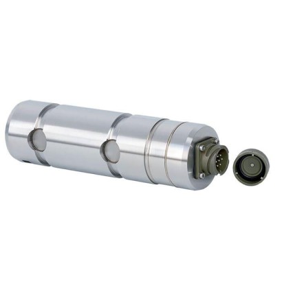
סיכת עומס
תיאור
סיכות עומס מדגמים F5308, F53C8 ו-F53S8 מתאימות למשימות מדידה סטטיות ודינמיות כתחליף לברגים שאינם מיועדים למדידה. הן משמשות לקביעת כוחות מתיחה ו/או דחיסה בתנאי עבודה קשים.
סיכות עומס כאלה נעשה בהן שימוש לעיתים קרובות במערכות הרמה ובמערכות מנופים, למשל במנופי בנייה או במנופי נמל ובמנופים ימיים.
האישורים הטכניים והאזוריים המתאימים של משדרי כוח אלה זמינים כמובן כאפשרויות.
לאישורים נוספים ראה עמוד 4
סיכות עומס, דגמים F5308 (איור תחתון), F53S8 (איור עליון)
סיכות העומס עשויות מפלדת אל-חלד 1.4542 בעלת חוזק גבוה ועמידות בפני קורוזיה, שתכונותיה אידיאליות לאזורי היישום.
כאותות מוצא זמינים היציאות הסטנדרטיות של זרם ומתח פעילים (4 … 20 mA, 0 … 10 V). ניתן גם להציע אותות מוצא כפולים ופרוטוקולי CANopen ®.
ניתן לשלב את סיכות העומס בתוך מערכת הגנת עומס יתר מוסמכת של WIKA מדגם ELMS1 (DIN EN ISO 13849-1 עם PL d/cat. 3).
תזכורת: שמור בדיוק על 9 פסקאות המופרדות בשורה ריקה אחת, אל תאחד או תפצל פסקאות
תכונות מיוחדות
- טווחי מדידה מ- 0 ... 10 kN [מ- 0 ... 2,248 lbf]
- גרסה מפלדת אל-חלד עמידה לקורוזיה
- מגבר מובנה
- יציבות ארוכת טווח גבוהה, עמידות גבוהה לזעזועים ורעידות
- יכולת חזרה טובה, התקנה קלה
שאלות ותשובות
מהו טווח המדידה של סיכות העומס הללו?
טווחי המדידה מתחילים מ-0 … 10 kN [0 … 2,248 lbf].
מהם אותות המוצא הזמינים?
היציאות הסטנדרטיות הן זרם ומתח פעילים (4 … 20 mA, 0 … 10 V). ניתן להציע גם אותות מוצא כפולים ופרוטוקול CANopen®.
ממה עשויות סיכות העומס?
הסיכות עשויות מפלדת אל-חלד 1.4542 בעלת חוזק גבוה ועמידות בפני קורוזיה.
האם ניתן לשלב את הסיכות במערכת בטיחות?
כן. ניתן לשלב את סיכות העומס במערכת הגנת עומס יתר מוסמכת של WIKA מדגם ELMS1 לפי DIN EN ISO 13849-1 עם PL d/cat. 3.
מה מבדיל דגמים אלה מסיכות עומס אחרות?
מדובר בגרסת Heavy Duty עם טכנולוגיית שכבה דקה ומגבר מובנה, המתאימה כתחליף ישיר לברגים קיימים שאינם מיועדים למדידה, גם במשימות מדידה דינמיות ובתנאי עומס קשים.
האם הסיכות מתאימות למדידה סטטית ודינמית?
כן, הדגמים F5308, F53C8 ו-F53S8 מתאימים הן למשימות מדידה סטטיות והן לדינמיות, וכוללים יציבות ארוכת-טווח ועמידות גבוהה לזעזועים ורעידות.
| Model | F5308 and F53C8 with UL | F53S8 |
|---|---|---|
| Rated force F nom kN [lbf] | From 10 [ab 2,248] | |
| Relative linearity error d lin 1) | ±1%F nom / ±1.5%F nom | |
| Relative repeatability error in unchanged mounting position b rg | ±0.2%F nom | |
| Temperature effect on | ||
| the characteristic valueTK c | 0.2%F nom / 10 K | |
| the zero signalTK 0 | 0.2%F nom / 10 K | |
| Force limit F L | 200%F nom | |
| Breaking force F | 500%F nom | |
| B Transverse force effect d Q (signal at 100%F nom under 90°) | ±5%F nom | |
| Rated displacement (typical) s nom | < 0.1 mm[< 0.004 in] | |
| Material of the measuring body | ■ Corrosion-resistant stainless steel, 1.4542, ultrasound-tested 3.1 material ■ Version with 3.2 material available | |
| Rated temperature B T, nom | ■ -20 …+80 °C [-4 ...+176 °F] ■ -40 …+120 °C [-40 ...+248 °F] | -20 …+80 °C [-4 ...+176 °F] |
| Service temperature B T, G | ■ -30 …+80 °C [-22 ...+176 °F] ■ -40 …+80 °C [-40 ...+176 °F] | -30 …+80 °C [-22 ...+176 °F] |
| Storage temperature B T, S | -40 …+85 °C [-40 ...+185 °F] | |
| Electrical connection | ■ Circular connector M12 x 1, 4- or 5-pin ■ CANopen ® M12 x 1 circular connector, 5-pin ■ MIL connector | ■ 2-connector version M12 x 1, 4-pin ■ MIL connector |
| Output signal (rated characteristic value) C nom | ■ 4 …20mA, 2-wire ■ 4 …20mA, 3-wire ■ 2 x 4 …20mAredundant ■ DC 0 …10V, 3-wire ■ 2 x DC 0 …10Vredundant ■ Signal jump 4 ... 16 mA, 2-wire 4) DC 2 ... 8 V, 3-wire 4) ■ CANopen ® Protocol in accordance with CiA ® 301, device profile CiA ® 404, communication services LSS (CiA ® 305), configuration of the instrument address and baud rate Sync/Async, Node/ Lifeguarding, heartbeat; zero and span ±10% | Redundant, opposing 4…20mA/20…4mA Version in accordance with requirements for functional safety per machinery directive 2006/42/EC asWIKA overload protection with model ELMS1 (DIN EN ISO 13849-1 with PL d/cat. 3). |
| Current/power consumption | ■ Current output 4 …20mA, 2-wire: signal current ■ Current output 4 ...20 mA, 3-wire:<8mA ■ Voltage output:<8mA ■ CANopen ® :<1W | Voltage output: < 8 mAper channel |
| Supply voltage UB | ■ DC 9 ...36V for current output ■ DC 13 ...36V for voltage output ■ DC 9 ...36V for CANopen ® | DC10…30V |
| Load | ■ ≤ (UB-10 V)/0.024 A for current output ■ > 10 kΩ for voltage output | ■ ≤ (UB - 10 V) / 0.020 A (channel 1) ■ ≤ (UB - 7 V) / 0.020 A (channel 2) |
| Reponse time | ≤ 2 ms (within 10 ...90%F nom ) 3) | |
| Ingress protection (per IEC/EN 60529) | ||
| Unplugged | IP66, IP67 | IP67 |
| state Plugged-in state | IP68, IP69, IP69K | |
| Electrical protection | Reverse polarity protection, overvoltage and short-circuit | resistance |
| Vibration resistance | 20 g, 100 h, 50 ... 150 Hz (in accordance with DIN EN 60068-2-6) | |
| Shock resistance | In accordance with DIN EN 60068-2-27 | |
| Immunity | In accordance with DIN EN 61326-1/DIN EN 61326-2-3 (optional | EMC-strengthened versions) |
| Intended use | Indoor and outdoor use, typically at altitudes of up to 2,500 | m[8,202.5 ft] above sea level. |
| Model | F53C8 ATEX/IECEx EX ib 1) | F53C8 ATEX/IECEx Ex d |
|---|---|---|
| Rated force F nom kN [lbf] | From 10 [ab 2,248] | |
| Relative linearity error d lin 2) | ±1%F nom / ±1.5%F nom | |
| Relative repeatability error in unchanged mounting position b rg | ±0.2%F nom | |
| Temperature effect on | ||
| the characteristic valueTK c | 0.2%F nom / 10 K | |
| the zero signalTK 0 | 0.2%F nom / 10 K | |
| Force limit F L | 200%F nom | |
| Breaking force F B | 500%F nom | |
| Transverse force effect d Q (signal at 100%F nom under 90°) 3) | ±5%F nom | |
| Rated displacement (typical) s nom | < 0.1 mm[< 0.004 in] | |
| Material of the measuring body | ■ Corrosion-resistant stainless steel, 1.4542, ultrasound-tested 3.1 material ■ Version with 3.2 material available | |
| Rated temperature B T, nom | -20 …+80 °C [-4 ...+176 °F] | |
| Service temperature B T, G | Ex II 2G Ex ib IIC T4 Gb -25 °C <Tamb < +85 °C Ex II 2G Ex ib IIC T3 Gb -25 °C <Tamb < +100 °C Ex I M2 Ex ib I Mb -25 °C <Tamb < +85 °C | Ex II 2G Ex d IICT4 Gb -40 °C <Tamb < +85 °C |
| Storage temperature B T, S | -40 …+85 °C [-40 ...+185 °F] | |
| Electrical connection | ■ Circular connector M12 x 1, 4-pin ■ MIL connector ■ Cable gland | Cable gland (only with ATEX/IECEx-Ex d - certified cable) |
| Output signal (rated characteristic value) C nom | ■ 4 …20mA, 2-wire | ■ 4 …20mA, 2-wire ■ 4 …20mA, 3-wire |
| Current/power consumption | ■ Current output 4 …20mA, 2-wire: signal current | ■ Current output 4 …20mA, 2-wire: signal current ■ Current output 4 …20mA, 3-wire:<8mA |
| Supply voltage UB | DC 10 ...30V for current output | |
| Load | ■ ≤ (UB - 10 V) / 0.024 A for current output ■ > 10 kΩ for voltage output | |
| Reponse time | ≤ 2 ms (within 10 ...90%F nom ) 4) | |
| Ingress protection (per IEC/EN 60529) | IP67 | |
| Electrical protection | Reverse polarity protection, overvoltage and short-circuit resistance | |
| Vibration resistance | 20 g, 100 h, 50 ... 150 Hz (in accordance with DIN EN 60068-2-6) | |
| Shock resistance | In accordance with DIN EN 60068-2-27 | |
| Immunity | In accordance with DIN EN 61326-1/DIN EN 61326-2-3 (optional EMC-strengthened versions) |
| Logo | Description | Region |
|---|---|---|
| EU declaration of conformity EMCdirective | European Union |
| Signal | Description |
|---|---|
| UB | Voltage source for the sensor |
| UB+ | Sensor voltage supply (+) |
| UB- | Sensor voltage supply (-) |
| S+ | Output signal (+) |
| S- | Output signal (-) |
| 0V | 0V potential |
הצגת הכול (20)
| Signal | Description |
|---|---|
| A | Ammeter |
| V | Voltmeter |
| + - | Voltage source |
| Switch | |
| Shield [ground] |
| Signal | 4 ... 20 mA, 2-wire | Cable colour |
|---|---|---|
| UB+/S+ | 1 | Brown |
| 0V/S- | 3 | Black |
| Shield | Case / Connector | - |
| Signal | Description |
|---|---|
| UB | Voltage source for the sensor |
| UB+ | Sensor voltage supply (+) |
| UB- | Sensor voltage supply (-) |
| S+ | Output signal (+) |
| S- | Output signal (-) |
| 0V | 0V potential |
| Signal | Description |
|---|---|
| A | Ammeter |
| V | Voltmeter |
| + - | Voltage source |
| Switch | |
| Shield [ground] |
| Signal | 4 ... 20 mA, 3-wire | Cable colour |
|---|---|---|
| UB+ | 1 | Brown |
| S+ | 4 | Black |
| 0V/S- | 3 | Blue |
| Shield | Case / Connector | - |
| Signal | 0 ... 10 V, 3-wire | Cable colour |
|---|---|---|
| UB+ | 1 | Brown |
| S+ | 4 | Black |
| 0V/S- | 3 | Blue |
| Shield | Case / Connector | - |
| Signal | ATEX/IECEx EX ib and Ex d 4 ... 20 mA, 2-wire | Cable colour |
|---|---|---|
| UB+/S+ | 1 | Brown |
| 0V/S- | 3 | Blue |
| Shield | Case / Connector | - |
| Signal | ATEX/IECEx Ex d 4 ... 20 mA, 3-wire | Cable colour |
|---|---|---|
| UB+ | 1 | Brown |
| 0V/S- | 3 | Blue |
| S+ | 4 | Black |
| Shield | Case / Connector | - |
| Signal | Description |
|---|---|
| UB | Voltage source for the sensor |
| UB+ | Sensor voltage supply (+) |
| UB- | Sensor voltage supply (-) |
| UR | Voltage source for the signal jump |
| UR+ | Signal jump supply voltage (+) |
| UR- | Signal jump supply voltage (-) |
| S+ | Output signal (+) |
| S- | Output signal (-) |
| 0V | 0V potential |
| Signal | Description |
|---|---|
| A | Ammeter |
| V | Voltmeter |
| + - | Voltage source |
| Switch | |
| Shield [ground] |
| Signal | 4 ... 20 mA, 2-wire | Cable colour |
|---|---|---|
| UB+/S+ | 1 | Brown |
| 0V/S- | 3 | Blue |
| UR+ | 2 | White |
| UR- | 4 | Black |
| Shield | Case / Connector | - |
| Signal | 4 ... 20 mA, 3-wire | Cable colour |
|---|---|---|
| UB+ | 1 | Brown |
| 0V/S- | 3 | Blue |
| UR+ | 2 | White |
| UR- | 3 | Blue |
| S+ | 4 | Black |
| Shield | Case / Connector | - |
| Signal | 0 ... 10 V, 3-wire | Cable colour |
|---|---|---|
| UB+ | 1 | Brown |
| 0V/S- | 3 | Blue |
| UR+ | 2 | White |
| UR- | 3 | Blue |
| S+ | 4 | Black |
| Shield | Case / Connector | - |
| Signal | Description |
|---|---|
| UB | Voltage source for the sensor |
| UB+ | Sensor voltage supply (+) |
| UB- | Sensor voltage supply (-) |
| S+ | Output signal (+) |
| S- | Output signal (-) |
| CH1 | Channel 1 |
| CH2 | Channel 2 |
| CH1+2 | Channel 1 and channel 2 |
| 0V | 0V potential |
| Signal | Description |
|---|---|
| A | Ammeter |
| V | Voltmeter |
| + - | Voltage source |
| Switch | |
| Shield [ground] |
| Signal | 4 ... 20 mA, 2-wire | Cable colour |
|---|---|---|
| UB+/S+ (CH1) | 1 | Brown |
| UB+/S+ (CH2) | 2 | White |
| 0V/S- (CH1) | 3 | Blue |
| 0V/S- (CH2) | 4 | Black |
| Shield | Case / Connector | - |
לא מצאתם תשובה בתיעוד? מהנדס יענה במהלך יום עסקים.
שאלו מהנדס →