
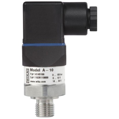
חיישן לחץ
תיאור
משדר הלחץ (חיישן לחץ) מדגם A-10, מוכח בשטח, הוא הפתרון הרב-תכליתי למדידת לחץ בסביבות תעשייתיות. בנוי בצורה קומפקטית, ניתן לשלב אותו במגוון רחב של תכנוני מכונות. טווחי המדידה הרבים, וכן טווחי מדידה ייעודיים, תורמים להתאמתו האוניברסלית.
תכונות מיוחדות
- איכות מעולה וטכנולוגיה מוכחת
- מגוון רחב במיוחד המכסה כמעט את כל היישומים
- כל הגרסאות הניתנות להגדרה זמינות בזמן קצר החל מכמות 1
- חסכוני במיוחד מבחינת עלות
שאלות ותשובות
מהו טווח המדידה של חיישן ה-A-10?
ה-A-10 מוצע במגוון רחב של טווחים: לחץ יחסי מ-0 … 0.05 bar ועד 0 … 1000 bar, טווחי ואקום ומשולבים (למשל -1 … 0 bar), טווחים מוחלטים עד 0 … 25 bar abs., וכן טווחים ב-inWC, inHg ו-psi.
מהי הדיוק של המשדר?
הדיוק הוא ≤ ±0.25 % of span, בהתאם לתקן IEC 61298-2.
אילו חיבורי תהליך זמינים?
בין היתר: M14 x 1.5, M20 x 1.5, G 1/8 B, G 1/4 B, G 1/2 B, 1/4 NPT, 1/2 NPT, R 1/2, PT 1/2, 7/16-20 UNF O-ring BOSS וחיבור פלנג'ה (Flange connection).
אילו אותות מוצא תומך המשדר?
4-20 mA, 0-10 V, 0-5 V, 1-5 V ו-0.5-4.5 V ratiometric, עם אספקת מתח של 10...30 V DC.
מהם גבולות הטמפרטורה המותרים?
הטמפרטורה המותרת הן לסביבה והן לתהליך היא -40 … +100 °C.
מהי דרגת ההגנה מפני חדירה?
דרגת ההגנה היא IP65.
מה מבדיל את ה-A-10 מדגמים אחרים?
ה-A-10 מיועד ליישומים תעשייתיים כלליים, עם מגוון חריג של טווחי מדידה, חיבורי תהליך ואותות מוצא הניתנים להגדרה, וזמינות מהירה החל מכמות 1 — בעלות תחרותית במיוחד.
| דגם | A-10 |
| תת-קטגוריה | Pressure transmitter |
| טווח לחץ | 0…0.05 bar · 0…0.1 bar · 0…0.16 bar · 0…0.25 bar · 0…0.4 bar · 0…0.6 bar · 0…1 bar · 0…1.6 bar · 0…2.5 bar · 0…4 bar · 0…6 bar · 0…10 bar · 0…16 bar · 0…25 bar · 0…40 bar · 0…60 bar · 0…100 bar · 0…160 bar · 0…250 bar · 0…400 bar · 0…600 bar · 0…1000 bar · -0.05…0 bar · -0.05…0.05 bar · -0.05…0.15 bar · -0.05…0.2 bar · -0.05…0.25 bar · -0.1…0 bar · -0.1…0.1 bar · -0.15…0.15 bar · -0.16…0 bar · -0.2…0.2 bar · -0.25…0 bar · -10…10 inWC · -20…0 inWC · -20…20 inWC · -40…0 inWC · -40…40 inWC · -50…50 inWC · -60…0 inWC · -75…75 inWC · 0…0.1 bar abs. · 0…0.16 bar abs. · 0…0.25 bar abs. · 0…0.4 bar abs. · 0…0.6 bar abs. · 0…1 bar abs. · 0…1.6 bar abs. · 0…5 psi abs. · 0…15 psi abs. · 0…25 psi abs. · 0…30 psi abs. · 0…50 psi abs. · 0…40 inWC abs. · 0…60 inWC abs. · 0…80 inWC abs. · 0…100 inWC abs. · 0…120 inWC abs. · 0…20 inWC · 0…40 inWC · 0…60 inWC · 0…80 inWC · 0…100 inWC · 0…120 inWC · 0…150 inWC · 0…200 inWC · 0…250 inWC · 0…400 inWC · -0.025…0.025 bar · -80…0 inWC · -100…0 inWC · -100…100 inWC · -120…0 inWC · -125…125 inWC · -150…0 inWC · -200…200 inWC · -250…0 inWC · 0…2.5 bar abs. · 0…4 bar abs. · 0…6 bar abs. · 0…10 bar abs. · 0…16 bar abs. · 0…25 bar abs. · 0…100 psi abs. · 0…150 psi abs. · 0…200 psi abs. · 0…300 psi abs. · 0…150 inWC abs. · 0…200 inWC abs. · 0…250 inWC abs. · 0…400 inWC abs. · 0…2.5 inWC abs. · 0…4 inWC abs. · 0…6 inWC abs. · 0…10 inWC abs. · 0…16 inWC abs. · 0…25 inWC abs. · 0…1 psi · 0…5 psi · 0…15 psi · 0…25 psi · 0…30 psi · 0…50 psi · 0…100 psi · 0…160 psi · 0…200 psi · 0…300 psi · 0…500 psi · 0…1000 psi · 0…1500 psi · 0…2000 psi · 0…3000 psi · 0…5000 psi · 0…10000 psi · 0…15000 psi · -1…0 psi · -30…0 inHg · -30…15 inHg · -30…30 inHg · -30…60 inHg |
| מחלקת דיוק | ≤ ±0.25 % of span |
| תקן דיוק | IEC 61298-2 |
| חיבור תהליך | M14 x 1.5M20 x 1.5G 1/4 AG 1/2 AG 1/8G 1/4G 3/8G 1/27/16-20 UNFG 1/8 BG 1/4 BG 1/4 female threadG 3/8 BG 1/2 B1/8 NPT1/4 NPT1/4 NPT, female thread1/2 NPTR 1/4R 3/8R 1/2PT 1/4PT 1/2PT 3/87/16-20 UNF O-ring BOSSFlange connection |
| טמפ׳ תהליך | −40…+100 °C |
| אות יציאה | 4-20 mA · 0-10 V · 0-5 V · 1-5 V · 0.5-4.5 V ratiometric · 0.5-4.5V |
| הזנה | 10...30 V DC |
| חיבור חשמלי | M12 4-pin, cable gland PG7/PG9/PG11/PG13.5 |
| חומר מארז | Stainless steel, Stainless steel 316L, PA and PBT, TPU and PUR |
| חומר חלקים רטובים | Stainless steel, Stainless steel 316L, PH grade steel, Synthetic oil, Dry measuring cell |
| חומר אטם | NBR, FPM/FKM, EPDM, Copper, Stainless steel, HNBR |
| טמפ׳ סביבה | −40…+100 °C |
| דרגת הגנה IP | IP65 |
| משקל | 0.08 kg |
| תקנים | CERoHSEACULNSF/ANSI/CAN 61China RoHS |
| שפות גיליון נתונים | EN, DE, ES, FR |
| Accuracy specifications | Non-linearity ≤ ±0.5 %of span | Non-linearity ≤ ±0.25 %of span |
|---|---|---|
| Non-linearity per BFSL per IEC 61298-2 | ||
| Measuring range ≤ 0.1 bar [≤ 1.45 psi] | ≤ ±0.5 %of span | - |
| Measuring range > 0.1 bar [> 1.45 psi] | ≤ ±0.5 %of span | ≤ ±0.25 %of span 1) |
| Accuracy | → See 'Max. measured error per IEC 61298-2' | |
| Max. measured error per IEC 61298-2 | ||
| Measuring range ≥ 0.6 bar [≥ 8.7 psi] | ≤ ±1 %of span | ≤ ±0.5 %of span |
| Measuring range ≥ 0.4 bar [≥ 5.8 psi] | ≤ ±1.2 %of span | ≤ ±0.7 %of span |
| Measuring range ≥ 0.25 bar [≥ 3.6 psi] | ≤ ±1.3 %of span | ≤ ±0.8 %of span |
| Measuring range ≥ 0.16 bar [≥ 2.3 psi] | ≤ ±1.5 %of span | ≤ ±1 %of span |
| Measuring range ≥ 0.1 bar [≥ 1.45 psi] | ≤ ±1.8 %of span | - |
| Measuring range ≥ 0.05 bar [≥ 0.73 psi] | ≤ ±2.4 %of span | - |
| Zero point error 2) 3) | ||
| 4 ... 20 mA/ DC 1 ...5V / DC 0.5 ...4.5V / DC 0.5 ...4.5V ratiometric | ≤ ±0.3 %of span | ≤ ±0.2 %of span |
| DC 0 ...10V | ≤ ±0.5 %of span | ≤ ±0.4 %of span |
| DC 0 ...5V 4) | ≤ ±0.6 %of span | - |
| Signal noise | ≤ 0.2 %of span | |
|---|---|---|
| Non-repeatability per IEC 61298-2 | ||
| Measuring range < 0.1 bar [< 1.45 psi] | ≤ 0.2 %of span | |
| Measuring range > 0.1 bar [> 1.45 psi] | ≤ 0.1 %of span | |
| Temperature error at 0 ... 80 °C [32 ... 176 °F] | ||
| - | Typical | ≤ ±1 %of span |
| Measuring range < 1 bar [< 14.5 psi] | Maximum | ≤ ±2.5 %of span |
| Measuring range ≥ 1 bar [≥ 14.5 psi] | Maximum | ≤ ±1.5 %of span |
| Measuring range ≥ 10 bar [≥ 145 psi] | Maximum | ≤ ±2 %of span |
| Measuring range > 25 bar [> 360 psi] | Maximum | ≤ ±1.5 %of span |
| Temperature hysteresis -30 ... +100°C [-22 ... +212 °F] for measuring ranges < 0.6 bar [< 8.7 psi] | ||
| Measuring range < 0.6 bar [< 8.7 psi] | Gauge pressure | ≤ 0.2 %of span |
| Absolute pressure | ≤ 0.2 %of span | |
| Measuring range < 0.4 bar [< 5.8 psi] | Gauge pressure | ≤ 0.3 %of span |
| Absolute pressure | ≤ 0.3 %of span | |
| Measuring range < 0.25 bar [< 3.6 psi] | Gauge pressure | ≤ 0.5 %of span |
| Absolute pressure | ≤ 0.5 %of span | |
| Measuring range < 0.16 bar [< 2.3 psi] | Gauge pressure | ≤ 0.7 %of span |
| Absolute pressure | ≤ 0.8 %of span | |
| Measuring range < 0.1 bar [< 1.45 psi] | Gauge pressure | ≤ 1.4 %of span |
| Long-term drift per IEC 61298-2 | |
|---|---|
| Measuring range ≤ 0.1 bar [≤ 1.45 psi] | ≤ ±0.5 %of span 1) |
| Measuring range ≤ 0.4 bar [≤ 5.8 psi] | ≤ ±0.2 %of span |
| Measuring range > 0.4 bar [> 5.8 psi] | ≤ ±0.1 %of span |
| Additional zero point error depending on the mounting position for measuring ranges ≤ 1 bar [≤ 15 psi] | |
| Mounting position 180°, vertical, top process connection | ≤ 1 mbar [≤ 0.015 psi] |
| Mounting position 90°, horizontal | ≤ 0.6 mbar [≤ 0.009 psi] |
| Reference conditions | Per IEC 61298-1 |
| bar | |
|---|---|
| 0 ... 0.05 | 0 ... 10 1) |
| 0 ... 0.1 | 0 ... 16 1) |
| 0 ... 0.16 | 0 ... 25 1) |
| 0 ... 0.25 | 0 ... 40 |
| 0 ... 0.4 | 0 ... 60 |
| 0 ... 0.6 | 0 ... 100 |
| 0 ... 1 | 0 ... 160 |
| 0 ... 1.6 | 0 ... 250 |
| 0 ... 2.5 | 0 ... 400 |
| 0 ... 4 | 0 ... 600 |
| 0 ... 6 | 0 ... 1,000 |
הצגת הכול (20)
| 0 ... 1 | 0 ... 300 1) |
|---|---|
| 0 ... 5 | 0 ... 500 |
| 0 ... 15 | 0 ... 1,000 |
| 0 ... 25 | 0 ... 1,500 |
| 0 ... 30 | 0 ... 2,000 |
| 0 ... 50 | 0 ... 3,000 |
| 0 ... 100 | 0 ... 5,000 |
| 0 ... 160 1) | 0 ... 10,000 |
| 0 ... 200 1) | 0 ... 15,000 |
| inWC | |
|---|---|
| 0 ... 20 | 0 ... 120 |
| 0 ... 40 | 0 ... 150 |
| 0 ... 60 | 0 ... 200 |
| 0 ... 80 | 0 ... 250 |
| 0 ... 100 | 0 ... 400 |
| 0 ... 0.1 | 0 ... 2.5 |
|---|---|
| 0 ... 0.16 | 0 ... 4 |
| 0 ... 0.25 | 0 ... 6 |
| 0 ... 0.4 | 0 ... 10 |
| 0 ... 0.6 | 0 ... 16 |
| 0 ... 1 | 0 ... 25 |
| 0 ... 1.6 | - |
| 0 ... 5 | 0 ... 100 |
|---|---|
| 0 ... 15 | 0 ... 150 |
| 0 ... 25 | 0 ... 200 |
| 0 ... 30 | 0 ... 300 |
| 0 ... 50 | - |
| 0 ... 40 | 0 ... 150 |
|---|---|
| 0 ... 60 | 0 ... 200 |
| 0 ... 80 | 0 ... 250 |
| 0 ... 100 | 0 ... 400 |
| 0 ... 120 | - |
| bar | |
|---|---|
| -0.025 ... +0.025 | -0.3 ... +0.3 |
| -0.05 ... 0 | -0.4 ... 0 |
| -0.05 ... +0.05 | -0.5 ... +0.5 |
| -0.05 ... +0.15 | -0.6 ... 0 |
| -0.05 ... +0.2 | -1 ... 0 |
| -0.05 ... +0.25 | -1 ... +0.6 |
| -0.1 ... 0 | -1 ... +1.5 |
| -0.1 ... +0.1 | -1 ...+3 |
| -0.15 ... +0.15 | -1 ...+5 |
| -0.16 ... 0 | -1 ...+9 1) |
| -0.2 ... +0.2 | -1 ...+15 1) |
| -0.25 ... 0 | -1 ...+24 1) |
| -10 ...+10 | -80 ... 0 |
|---|---|
| -20 ... 0 | -100 ... 0 |
| -20 ...+20 | -100 ...+100 |
| -40 ... 0 | -120 ... 0 |
| -40 ...+40 | -125 ...+125 |
| -50 ...+50 | -150 ... 0 |
| -60 ... 0 | -200 ...+200 |
| -75 ...+75 | -250 ... 0 |
| Units | ■ bar ■ psi ■ inWC ■ mbar ■ kg/cm² ■ MPa | |
|---|---|---|
| Maximum working pressure | → Corresponds to the upper measuring range value / measuring range full scale value → Any permanent operation above the maximum working pressure is not permis - sible | |
| Overpressure limit | The overpressure limit is based on the measuring range. Depending on the select - ed process connection and the seal, restrictions in overpressure limit can result. | |
| bar | Measuring ranges ≤ 0.1 bar | 0.2 bar |
| Measuring ranges ≤ 0.4 bar | 1 bar | |
| Measuring ranges < 1.6 bar | 3 bar | |
| Measuring ranges ≥ 1.6 bar | 2 times | |
| Measuring range 1,000 bar | 1.43 times | |
| bar abs. | Measuring ranges ≤ 0.4 bar abs. | 1 bar abs. |
| Measuring ranges < 1.6 bar abs. | 3 bar abs. | |
| Measuring ranges ≥ 1.6 bar abs. | 2 times | |
| psi | Measuring ranges ≤ 1 psi | 3 psi |
| Measuring ranges ≤ 5 psi | 14.5 psi | |
| Measuring ranges < 25 psi | 45 psi | |
| Measuring ranges ≥ 25 psi | 2 times | |
| Measuring ranges 160 psi, 1,000 psi, 1,500 psi and 10,000 psi | 1.7 times | |
| Measuring range 15,000 psi | 1.43 times | |
| psi abs. | Measuring ranges ≤ 5 psi abs. | 14.5 psi abs. |
| Measuring ranges < 25 psi abs. | 45 psi abs. | |
| Measuring ranges ≥ 25 psi abs. | 2 times |
| inWC | Measuring ranges ≤ 40 inWC | 80 inWC |
|---|---|---|
| Measuring ranges ≤ 200 inWC | 400 inWC | |
| Measuring ranges ≤ 400 inWC | 1,200 inWC | |
| inWC abs. | Measuring ranges ≤ 200 inWC abs. | 400 inWC abs. |
| Measuring ranges ≤ 400 inWC abs. | 1,200 inWC abs. | |
| Vacuum resistance | Yes (restriction with measuring ranges ≤ 0.1 bar [≤ 1 psi, 40 inWC]: -0.2 bar [-3 psi, -80 | |
| Leakage rate | ■ < 5*10 -3 mbar*l/s ■ < 1*10 -6 mbar*l/s 1) 2) |
| Standard | Thread size | Max. measuring range | Overpressure limit | Seal |
|---|---|---|---|---|
| EN 837 | G⅛B | 400 bar [5,000 psi] | 572 bar [8,290 psi] | Copper |
| G¼B | 1,000 bar [15,000 psi] | 1,480 bar [21,400 psi] | ■ Copper ■ Stainless steel | |
| G¼female thread | 1,000 bar [15,000 psi] | 1,480 bar [21,400 psi] | Without | |
| G⅜B | 1,000 bar [15,000 psi] | 1,480 bar [21,400 psi] | ■ Copper ■ Stainless steel | |
| G½B | 1,000 bar [15,000 psi] | 1,480 bar [21,400 psi] | ■ Copper ■ Stainless steel | |
| DIN EN ISO 1179-2 | G¼A | 600 bar [8,000 psi] | 858 bar [12,440 psi] | ■ NBR ■ EPDM |
| 1,000 bar [15,000 psi] | 1,480 bar [21,400 psi] | FPM/FKM | ||
| G½A | 600 bar [8,000 psi] | 858 bar [12,440 psi] | ■ NBR ■ FPM/FKM | |
| DIN EN ISO 9974-2 | M14 x 1.5 | 600 bar [8,000 psi] | 858 bar [12,440 psi] | ■ NBR ■ FPM/FKM ■ EPDM |
| ANSI/ASME B1.20.1 | ⅛NPT | 400 bar [5,000 psi] | 572 bar [8,290 psi] | - |
| ¼NPT | 1,000 bar [15,000 psi] | 1,480 bar [21,400 psi] | ||
| ¼NPT, female thread | 1,000 bar [15,000 psi] | 1,480 bar [21,400 psi] | ||
| ½NPT | 1,000 bar [15,000 psi] | 1,480 bar [21,400 psi] | ||
| DIN 16288 | M20 x 1.5 | 1,000 bar [15,000 psi] | 1,480 bar [21,400 psi] | ■ Copper ■ Stainless steel |
| ISO 7 | R¼ | 1,000 bar [15,000 psi] | 1,480 bar [21,400 psi] | - |
| R⅜ | 1,000 bar [15,000 psi] | 1,480 bar [21,400 psi] | ||
| R½ | 1,000 bar [15,000 psi] | 1,480 bar [21,400 psi] | ||
| KS | PT¼ | 1,000 bar [15,000 psi] | 1,480 bar [21,400 psi] | - |
| PT½ | 1,000 bar [15,000 psi] | 1,480 bar [21,400 psi] | ||
| PT⅜ | 1,000 bar [15,000 psi] | 1,480 bar [21,400 psi] | ||
| SAE J514 | 7/16-20 UNF O-ring BOSS | 600 bar [8,000 psi] | 858 bar [12,440 psi] | FPM/FKM |
| - | Flange connection | 100 bar [1,000 psi] | 143 bar [2,070 psi] | Without |
| Output signal | ||
|---|---|---|
| Signal type | ||
| Current (2-wire) | 4 ...20mA | |
| Voltage (3-wire) | ■ DC 0 ...10V ■ DC 0 ...5V ■ DC 1 ...5V ■ DC 0.5 ...4.5V | |
| Ratiometric (3-wire) | DC 0.5 ...4.5V | |
| Load Ω | ||
| Current (2-wire) | ≤ (auxiliary power - 8 V) / 0.02 A | |
| Voltage (3-wire) | > Maximum output signal /1mA | |
| Ratiometric (3-wire) | > 10k | |
| Voltage supply | ||
| Auxiliary power | Output signal 4 ...20mA | ■ DC 8 ...30V ■ DC 8 ...35V 1) 2) |
| Output signal DC 0 ...5V 1) 3) | ■ DC 8 ...30V ■ DC 8 ...35V | |
| Output signal DC 1 ...5V | ■ DC 8 ...30V ■ DC 8 ...35V | |
| Output signal DC 0.5 ...4.5V | ■ DC 8 ...30V ■ DC 8 ...35V | |
| Output signal DC 0 ...10V | ■ DC 14 ...30V ■ DC 14 ...35V | |
| Output signal DC 0.5 ... 4.5 V, ratiometric | DC 5V ±10% | |
| Current supply | Current (2-wire) | Signal current, max.25mA |
| Voltage (3-wire) | 8mA | |
| Ratiometric (3-wire) | 8mA |
| Dynamic behaviour | ||
|---|---|---|
| Settling time per IEC 61298-2 | Measuring range ≥ 0.4 bar [≥ 5.8 psi] | < 1 ms ⁴⁾ |
| Measuring range < 0.4 bar [< 5.8 psi] | < 1 min | |
| Switch-on time | Measuring range ≥ 0.4 bar [≥ 5.8 psi] | < 15 ms |
| Measuring range < 0.4 bar [< 5.8 psi] | < 1 min |
| Connection type | IP code 1) | Wire cross-section | Cable diameter | Cable material |
|---|---|---|---|---|
| Angular connector DIN EN 175301-803 A | ||||
| With mating connector, PG9 (stand - ard) | IP65 | To max. 1.5 mm² | 6 ...8mm | - |
| With mating connector, PG11 | IP65 | To max. 1.5 mm² | 8 ...10mm | |
| With mating connector, PG13.5 2) | IP65 | To max. 1.5 mm² | 10 ...14mm | |
| With moulded cable 3) | IP65 | 3 x 0.75 mm² | 6mm | PUR |
| Angular connector DIN EN 175301-803 C 3) | ||||
| With mating connector | IP65 | To max. 0.75 mm² | 4.5 ...6mm | - |
| Circular connector M12 x 1 (4-pin) | ||||
| Without mating connector | IP67 | - | - | - |
| Straight with moulded cable 3) | IP67 | 3 x 0.34 mm² | 4.3mm | PUR |
| Angled with moulded cable 3) | IP67 | 3 x 0.34 mm² | 4.3mm | PUR |
| Cable outlet | ||||
| Unshielded 3) | IP67 | 3 x 0.34 mm² | 4mm | PUR |
| OEMversion, unshielded 4) | IP67 | 3 x 0.14 mm² | 2.85mm | TPU |
| Connection type | → See table 'Electrical connection' on page 7 |
|---|---|
| Wire cross-section | → See table 'Electrical connection' on page 7 |
| Cable diameter | → See table 'Electrical connection' on page 7 |
| Pin assignment | → See table 'Pin assignment' |
| Ingress protection (IP code) per IEC 60529 | → See table 'Electrical connection' on page 7 |
| Short-circuit resistance | S+ vs. U- |
| Reverse polarity protection | U+ vs. U- No reverse polarity protection with ratiometric output signal |
| Insulation voltage | DC 500V |
| 2-wire | 3-wire | ||
|---|---|---|---|
| U + | 1 | 1 | |
| U- | 2 | 2 | |
| S+ | - | 3 |
| 2-wire | 3-wire | ||
|---|---|---|---|
| 1 2 3 | U + | 1 | 1 |
| U- | 2 | 2 | |
| S+ | - | 3 |
לא מצאתם תשובה בתיעוד? מהנדס יענה במהלך יום עסקים.
שאלו מהנדס →1 מק״טים סטנדרטיים של משפחת A-10
אם ידוע הקוד — בחרו ישירות. אם לא — השתמשו בתצורה במצב «01».