
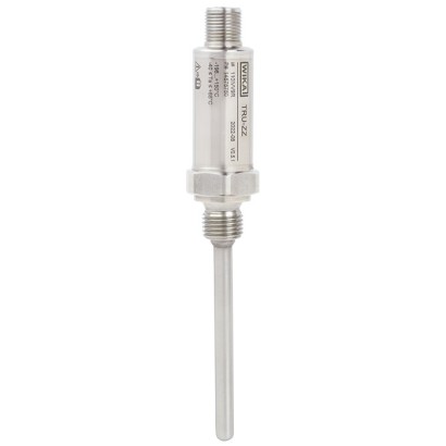
Miniature resistance thermometer for connection to WIKA radio unit
Description
The model TRU miniature resistance thermometer in combination with the model NETRIS ® 3 radio unit is used wherever web-based remote monitoring of the process pressure is desired. Condition-based and preventive maintenance through centralised big data analysis is thus possible.
Resistance thermometers in this series can be installed directly into the process or combined with a large number of thermowell designs. Surface temperature measurements, e.g. on a tubeskin, can be performed using a tightening strap. The instruments are intrinsically safe and suitable for use in hazardous areas.
for further approvals, see page 5
Special features
- IIoT-capable measuring instrument in combination with WIKA radio unit, model NETRIS ® 3
- Sensor range from -196 ... +500 °C [-321 ... +932 °F]
- For direct installation into the process or common thermowell designs
- Intrinsically safe version Ex i
- Very compact design
| Model | TRU |
| Subcategory | Miniature resistance thermometer with integrated transmitter |
| Temperature ranges | −196…+300 °C · −50…+300 °C · −50…+500 °C |
| Accuracy class | ±1.9 K (≤ 300 °C), ±2.9 K (> 300 °C) |
| Process connection | M12 x 1.5M20 x 1.57/16-20 UNF-2AwithoutM24 x 1.5 female thread, spring-loaded sensorG ¼ BG ⅜ BG ½ B¼ NPT½ NPTG ¼ B compression fitting (metal ferrule)G ⅜ B compression fitting (metal ferrule)G ½ B compression fitting (metal ferrule)¼ NPT compression fitting (metal ferrule)½ NPT compression fitting (metal ferrule)G ¼ B compression fitting (PTFE ferrule)G ⅜ B compression fitting (PTFE ferrule)G ½ B compression fitting (PTFE ferrule)¼ NPT compression fitting (PTFE ferrule)½ NPT compression fitting (PTFE ferrule)G ⅜ union nut, spring-loaded sensorTightening strap7/16-20 UNF-2A with O-ringM24x1.5 female thread1/4 NPT1/2 NPTCompression fittingSpring-loadedTubeskin with tightening strap |
| Process temperature | −196…+500 °C |
| Output signal | Unified WIKA interface (UWI) · Digital interface (UWI) |
| Electrical connection | M12 x 1 circular connector |
| Probe material | 1.4435 (316L), Stainless steel 1.4571 (316 Ti), Stainless steel 1.4435 (316L), 1.4571 (316 Ti) |
| Thermowell material | 1.4571 (316 Ti), 1.4435 (316L) |
| Ambient temperature | −40…+105 °C |
| IP rating | IP66/IP67 |
| Weight | 0.05 kg |
| Certifications | CERoHSATEXIECEx |
| Explosion protection | II 1D Ex ia IIIC * DaII 1/2D Ex ia IIIC * Da/DbII 2D Ex ia IIIC * DbII 1G Ex ia IIC T1 - T6 GaII 1/2G Ex ia IIC T1 - T6 Ga/GbII 2G Ex ia IIC T6 GbII 2G Ex ia IIC T1 - T6 Gb |
| Sensor type | Pt100 |
| Probe length | 50 mm |
| Probe diameter | 3 mm |
| Thermowell | No |
| Thermowell form | fabricated |
| Datasheet languages | EN, DE |
| Process connection | |
|---|---|
| Type of process connection | ■ G¼B ■ G⅜B ■ G½B ■ ¼NPT ■ ½NPT ■ M12 x 1.5 ■ M20 x 1.5 ■ 7/16-20 UNF-2A ■ without ■ G¼Bcompression fitting (metal ferrule) ■ G⅜Bcompression fitting (metal ferrule) ■ G½Bcompression fitting (metal ferrule) ■ ¼4 NPT compression fitting (metal ferrule) ■ ½NPTcompression fitting (metal ferrule) ■ G¼Bcompression fitting (PTFE ferrule) ■ G⅜Bcompression fitting (PTFE ferrule) ■ G½Bcompression fitting (PTFE ferrule) ■ ¼NPTcompression fitting (PTFE ferrule) ■ ½NPTcompression fitting (PTFE ferrule) ■ G⅜union nut, spring-loaded sensor (for additional thermowell) ■ M24 x 1.5 female thread, spring-loaded sensor (for additional thermowell / neck tube) |
| Sensor | |
| Sensor diameter | ■ 3 mm[0.12 in] ■ 6 mm[0.24 in] |
| Insertion length 1) | ■ 50 mm[1.97 in] ■ 75 mm[2.95 in] ■ 100 mm[3.94 in] ■ 120 mm[4.72 in] ■ 150 mm[5.91 in] ■ 200 mm[7.87 in] ■ 250 mm[9.84 in] ■ 300 mm[11.81 in] ■ 350 mm[13.78 in] ■ 400 mm[15.75 in] Other insertion lengths on request |
| Signal type | UnifiedWIKA interface (UWI) |
|---|---|
| Digital signal resolution | 10mK |
| Connection type | M12 x 1 circular connector, pin assignment suitable for use withWIKA radio unit model NETRIS ® 3 |
| Accuracy | Overall accuracy incl.WIKA radio unit (NETRIS ® 3): ■ Measuring range ≤ 300 °C: +/- 1.9 °K ■ Measuring range > 300 °C: +/- 2.9 °K |
| Materials (wetted) | |
|---|---|
| Sheath material | ■ Stainless steel 1.4571 (316 Ti) ■ Stainless steel 1.4435 (316L) |
| Process connection | ■ Stainless steel 1.4571 (316 Ti) ■ Stainless steel 1.4435 (316L) |
| Ambient and storage temperature range | -40 ...+105 °C [-40 ...+221 °F] |
|---|---|
| Version with FKM O-ring -20 ...+105 °C [-4 ...+221 °F] | |
| Climate class per IEC 60654-1 | Cx (-40 ...+105 °C [-40 ...+221 °F], 5 ... 95 %r.h.) |
| Version with FKM O-ring: -20 °C [-4 °F] | |
| Maximum permissible humidity, condensation | 100 %r.h., condensation allowed |
| Maximum operating pressure 1) 2) | |
| With sensor diameter 3 mm[0.12 in] | 140 bar [2,030 psi] |
| With sensor diameter 6 mm[0.24 in] | 270 bar [3,916 psi] |
| Salt mist | IEC 60068-2-11 |
| Vibration resistance per IEC 60751 | 10 ... 2,000 Hz, max. 10 g amplitude / 20 g peak-to-peak 3) |
| Shock resistance per IEC 60068-2-27 | 50 g, 6 ms, 3 axes, 3 directions, three times per direction |
| Ingress protection (IP code) | |
| Case with connected connector | ■ IP66 per IEC/EN 60529 ■ IP67 per IEC/EN 60529 |
| The stated ingress protection only applies when plugged in using line connec- tors that have the appropriate ingress protection. | |
| Coupler connector, not connected | IP67 per IEC/EN 60529 |
| Weight | Approx. 0.05 ... 0.7 kg [0.11 ... 1.54 lbs] - depending on version |
View all (8)
| Hazardous gas atmos- phere | Temperature class | Ambient temperature range (T a ) | Process temperature |
|---|---|---|---|
| II 1G Ex ia IIC T1 - T6 Ga II 1/2G Ex ia IIC T1 - T6 Ga/Gb II 2G Ex ia IIC T1 - T6 Gb | T6 | -40 ...+50 °C [-40 ...+122 °F] | -196 ... +72.5 °C [-321 ...+163 °F] |
| T5 | -40 ...+75 °C [-40 ...+167 °F] | -196 ... +87.5 °C [-321 ...+190 °F] | |
| T4 | -40 ...+105 °C [-40 ...+221 °F] | -196 ... +122.5 °C [-321 ...+253 °F] | |
| T3 | -40 ...+105 °C [-40 ...+221 °F] | -196 ... +187.5 °C [-321 ...+370 °F] | |
| T2 | -40 ...+105 °C [-40 ...+221 °F] | -196 ... +282.5 °C [-321 ...+541 °F] | |
| T1 | -40 ...+105 °C [-40 ...+221 °F] | -196 ... +432.5 °C [-321 ...+811 °F] |
| Hazardous dust/air atmos- pheres | Temperatur class / maximum surface temperature | Ambient temperature range (T a ) | Process temperature |
|---|---|---|---|
| II 1D Ex ia IIIC * Da II 1/2D Ex ia IIIC * Da/Db II 2D Ex ia IIIC * Db | T135 °C T 200 xxx °C | -40 ...+100 °C [-40 ... 212 °F] | -196 ... xxx °C - 9 K 1) |
| Logo | Description | Region | |
|---|---|---|---|
| EU declaration of conformity | European Union | ||
| RoHS directive ATEX directive Hazardous areas - | |||
| Ex i Zone 0 gas Zone 1 mounting to zone 0 gas Zone 1 gas Zone 20 dust Zone 21 mounting to zone 20 dust Zone 21 dust | II 1G Ex ia IIC T1 ...T6 Ga II 1/2G Ex ia IIC T1 ...T6 Ga/Gb II 2G Ex ia IIC T1 ...T6 Gb II 1D Ex ia IIIC * Da II 1/2D Ex ia IIIC * Da/Db II 2D Ex ia IIIC * Db | ||
| IECEx - in combination with ATEX Hazardous areas | International | ||
| - Ex i Zone 0 gas Zone 1 mounting to zone 0 gas Zone 1 gas Zone 20 dust Zone 21 mounting to zone 20 dust Zone 21 dust | Ex ia IIC T1 ...T6 Ga Ex ia IIC T1 ...T6 Ga/Gb Ex ia IIC T1 ...T6 Gb Ex ia IIIC * Da Ex ia IIIC * Da/Db Ex ia IIIC * Db |
| Description | Relevant data sheet | Further information |
|---|---|---|
| NETRIS ® 3 radio unit | AC 40.03 | on request |
Couldn't find the answer in the documentation? An engineer will reply within a business day.
Ask an engineer →1 standard articles of family TRU
If you know the code — pick directly. If not — use the configurator in mode “01”.