
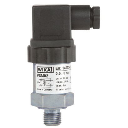
WIKA · Pressure measurement · Family PSM
Compact pressure switch
For industrial applications, adjustable switch hysteresis
Range
-0.85…320 bar
Accuracy
≤ 2 %
Protection
IP65
CEEACRoHSEMCLow voltage directive
Price
From €64
Confirm at order time
Description
Model PSM02 screw-in pressure switches in a diaphragm or piston design open or close a circuit, depending on whether the pressure is falling or rising. With one adjustment screw, respectively, the required switch point and the switch hysteresis can also be easily and conveniently set on-site. Optionally, WIKA offers its customers the factory setting of
the switch point.
Special features
- Adjustable switch hysteresis
- Setting ranges: 0.2 … 2 bar [3 ... 30 psi] to 30 ... 320 bar [450 ... 4,600 psi] and -0.85 ... -0.15 bar [-25 inHg ... -5 inHg]
- Non-repeatability of the switch point: ≤ 2 %
- Switching functions: Normally closed, normally open or change-over contact
- Media: Compressed air, neutral and self-lubricating fluids and neutral gases
Configurator · Step by step
Build a PSM02 for your task
The article number is assembled automatically. If unsure — ask an engineer; we'll match the line's parameters.
Step 1 of 2
Your configuration
- ModelPSM02
- Material process connectionsteel galvanised
- Case materialsteel galvanised
- Switching functionSPDT
- Setting of switching pointAdjustable
- Unitbar
- Setting range-0.85 ... -0.15 bar
- Maximum system pressure20 bar (Vacuum)
- measuring principleMembrane
- Process connection WN02.062G 1/8 B acc. to ISO228-1
- diaphragm/sealing material—
- Diaphragm/sealing material—
- Electrical connectorDIN EN 175301-803 with cable box
- Cable length0
- Unit of switching pointwithout
- Switch point0
- Switching directionwithout
- Switching hysteresiswithout
AI suggestion by parameters
Finish your configuration
Select every option to submit the request.
Identification
| Model | PSM02 |
| Product family | PSM |
| Subcategory | Mechanical pressure switch |
Measuring range
| Pressure ranges | 0.2…2 bar · 0.5…8 bar · 1…16 bar · 10…30 bar · 10…80 bar · 10…120 bar · 20…200 bar · 20…250 bar · 30…320 bar · 3…30 psi · 7…115 psi · 15…225 psi · 150…425 psi · 150…1150 psi · 150…1700 psi · 150…2300 psi · 300…2900 psi · 300…3600 psi · 450…4600 psi · -25…-5 inHg · -0.85…-0.15 bar |
Accuracy
| Accuracy class | ≤ 2 % |
| Accuracy standard | ISO 10771-1 |
Process conditions
| Process connection | M10 x 17/16-20 UNF BOSSG ¼ B¼ NPTR ¼G ⅛ BG ½ B⅛ NPTR ⅛G 1/8 BG 1/4 BG 1/2 B1/8 NPT1/4 NPTR 1/8R 1/4 |
| Process temperature | −40…+100 °C |
Electrical characteristics
| Electrical connection | Angular connector DIN 175301-803 A (4-pin), Circular connector M12 x 1 (4-pin), Cable outlet |
| Switching function | Normally open, normally closed, change-over contact |
| Switching contacts | 1 |
Materials
| Case material | Galvanised steel, Stainless steel |
| Wetted parts material | Galvanised steel, Stainless steel 303, PTFE |
| Sealing material | NBR, FKM, EPDM, TNBR, FVMQ |
Operating environment
| Ambient temperature | −20…+80 °C |
| IP rating | IP65 |
| Weight | 0.14 kg |
Certifications and approvals
| Certifications | CEEACRoHSEMCLow voltage directive |
Additional details
| Datasheet languages | EN |
Tables from datasheet
| Unit | Max. working pres- sure | Setting range | Non-repeatability 1) | Measurement principle |
|---|---|---|---|---|
| bar | 20 | -0.85 …-0.15 | ±0.05 | Diaphragm |
| 60 | 0.2…2 | ±0.04 | ||
| 0.5…8 | ±0.16 | |||
| 1…16 | ±0.32 | |||
| 350 | 10…30 | ±0.6 | Piston | |
| 10…80 | ±1.6 | |||
| 10 …120 | ±2.4 | |||
| 20 …200 | ±4 | |||
| 20 …250 | ±5 | |||
| 30 …320 | ±6.4 | |||
| psi | 300 | -25 …-5 inHg | ±1.4 inHg | Diaphragm |
| 870 | 3…30 | ±0.6 | ||
| 7 …115 | ±2.3 | |||
| 15 …225 | ±4.5 | |||
| 5,000 | 150 …425 | ±8.5 | Piston | |
| 150 …1,150 | ±23 | |||
| 150 …1,700 | ±34 | |||
| 150 …2,300 | ±46 | |||
| 300 …2,900 | ±58 | |||
| 300 …3,600 | ±72 | |||
| 450 …4,600 | ±92 |
| Electrical connection | Normally open | Normally closed | Change-over contact |
|---|---|---|---|
| Angular connector DIN 175301-803 A (4-pin) | - | - | x |
| Circular connector M12 x 1 (4-pin) | - | - | x |
| Cable outlet | x | x | x |
| Utilization category 1) | Voltage | Current | ||
|---|---|---|---|---|
| Angular connector | M12 x 1, cable | All | ||
| Resistive load AC-12, DC 12 | AC 250V | AC 48V | DC 24V | 4 A |
| Inductive load AC-14, DC 14 | AC 250V | AC 48V | DC 24V | 2 A |
| Min. switching power | 25 mWwith solid silver contacts |
| Non-repeatability (guideline value) | Switch point setting |
|---|---|
| ≤ 2 %of setting range end value | No factory setting, adjustable |
| Factory setting, adjustable | |
| ≤ 4 %of set switch point 2) | Fixed factory setting, not adjustable |
View all (11)
| Measurement principle | Switch hysteresis (guideline value) |
|---|---|
| Diaphragm (vacuum) | 250 mbar |
| Diaphragm (gauge pressure) | 0.1 bar [1.4 psi] + 5 ... 20 %of switch point Example:With a switch point of 3 bar [42 psi], the switch hysteresis is 0.25 ... 0.7 bar [3.5 ... 9.8 psi]. |
| Piston | 5 bar [70 psi] + 5 ... 15 %of switch point Example:With a switch point of 100 bar [1,500 psi], the switch hysteresis is 10 ... 20 bar [145 ... 290 psi]. |
| Medium temperature | Sealing material |
|---|---|
| -20 …+80 °C [-4 ... +176 °F] | NBR |
| 0 …100 °C [32 ... 212 °F] | FKM |
| -40 …+100 °C [-40 ... +212 °F] | EPDM |
| -40 …+80 °C [-40 ... +176 °F] | TNBR |
| -40 ... +100 °C [-40 ... +212 °F] | FVMQ |
| Thread | Process connection standard | Material of wetted parts |
|---|---|---|
| G⅛B | DIN EN ISO 228-1 | ■ Galvanised steel ■ Stainless steel |
| G ¼ B | DIN EN ISO 228-1 | Stainless steel |
| G½B | DIN EN ISO 228-1 | Stainless steel (only with measurement principle: Diaphragm) |
| M10 x 1 | DIN 13-5 | Galvanised steel |
| 7/16-20 UNF BOSS | SAE J514 E | ■ Galvanised steel ■ Stainless steel |
| ⅛NPT | ANSI/ASME B1.20.1 | ■ Galvanised steel ■ Stainless steel |
| ¼ NPT | ANSI/ASME B1.20.1 | ■ Galvanised steel ■ Stainless steel |
| R⅛ | ISO 7 | ■ Galvanised steel ■ Stainless steel |
| R ¼ | ISO 7 | ■ Galvanised steel ■ Stainless steel |
| Designation | Ingress protection 1) | Wire cross-section | Cable ∅ |
|---|---|---|---|
| Angular connector DIN 175301-803 A (4-pin) | IP65 | - | - |
| Circular connector M12 x 1 (4-pin) | IP67 | - | - |
| Cable outlet, 2-wire 2) | IP67 | 2 x 0.75 mm² [1.16 x 10 -3 in²] | 5.0 mm[0.2 in] |
| Cable outlet, 3-wire 2) | IP67 | 3 x 0.5 mm² [7.75 x 10 -4 in²] | 5.3 mm[0.21 in] |
| Logo | Description | Country |
|---|---|---|
| EU declaration of conformity ■ Pressure equipment directive ■ Low voltage directive ■ RoHS directive | European Union | |
| EAC ■ EMCdirective ■ Low voltage directive | Eurasian Economic Community |
| Designation | Order number | |||
|---|---|---|---|---|
| without cable | with 2 mcable | with 5 mcable | with 10 mcable | |
| Circular connector M12 x 1 (4-pin) | ||||
| ■ straight | 2421262 | 14086880 | 14086883 | 14086884 |
| ■ angled | 2421270 | 14086889 | 14086891 | 14086892 |
| G | L1 |
|---|---|
| ⅛NPT | 10 [0.4] |
| ¼NPT | 12 [0.47] |
| R⅛ | 10 [0.4] |
| R¼ | 12 [0.47] |
Industry
Chemistry / Pharma
Plastics injection moulding machines
Industry
Machinery
Hydraulics and mobile hydraulics · Pneumatics
Couldn't find the answer in the documentation? An engineer will reply within a business day.
Ask an engineer →All variants · Article table
4 standard articles of family PSM
If you know the code — pick directly. If not — use the configurator in mode “01”.
Stock:
SKUConfigurationPriceStockAction
PSM02-11-30B0110-P081Z-Z-3ZZ-ZZZZZZZ2Model: PSM02 · Material process connection: 1 · Case material: 1+ 15 moreOn requestOn orderRequest →
PSM02-11-30B0110-P082Z-Z-3ZZ-ZZZZZZZ2Model: PSM02 · Material process connection: 1 · Case material: 1+ 15 moreOn requestOn orderRequest →
PSM02-11-30B0110-P084Z-Z-3ZZ-ZZZZZZZ2Model: PSM02 · Material process connection: 1 · Case material: 1+ 15 moreOn requestOn orderRequest →
PSM02-11-30B0110-P088Z-Z-3ZZ-ZZZZZZZ2Model: PSM02 · Material process connection: 1 · Case material: 1+ 15 moreOn requestOn orderRequest →
Showing 4 of 4. Price on request — an engineer will quote your configuration.