
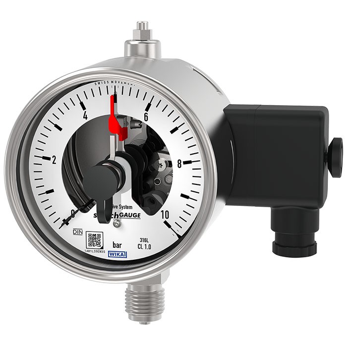
Bourdon tube pressure gauge with switch contacts
Description
Wherever the process pressure has to be indicated locally and, at the same time, circuits need to be switched, this switchGAUGE finds its use.
Switch contacts (electrical switch contacts) make or break an electric control circuit dependent upon the pointer position of the indicating measuring instrument. The switch contacts are adjustable over the full extent of the scale range (see DIN 16085), and are mounted predominantly below the dial, though also partly on top of the dial. The instrument pointer (actual value pointer) moves freely across the entire scale range, independent of the setting.
The set pointer can be adjusted using a removable adjustment key in the window.
Special features
- Also available with case filling for high dynamic pressure loads or vibrations
- Instruments with inductive contacts for use in hazardous areas
- Instruments with contacts for PLC applications
- Safety version with solid baffle wall (Solidfront) available
- QR code on dial links to instrument-specific information
Build a PGS23.1X0 for your task
The article number is assembled automatically. If unsure — ask an engineer; we'll match the line's parameters.
- ModelPGS23
- Nominal size100
- switchmagnetic snap action switch, model 821
- first switch operationmakes (1)
- second switch operationwithout
- third switch operationwithout
- Explosion protectionwithout
- Electrical connectionplug sidewise
- Contact designwithout
- Unit of outer Scalebar
- Measuring rangegauge pressure range
- Scale range—
- 2nd Scale or Special Scalewithout
- Process connectionG 1/2 B
- Connection locationlower mount
- Liquid Damping (case filling)without filling
- Casewith pressure blowout disk
- Mounting optionwithout
- Restrictorwithout
- Special design featureswithout
- Certificateswithout
Finish your configuration
Select every option to submit the request.
| Model | PGS23.100 |
| Product family | PGS23 |
| Subcategory | Switch gauge with electrical contacts |
| Pressure ranges | 0…0.6 bar · 0…1 bar · 0…1.6 bar · 0…2.5 bar · 0…4 bar · 0…6 bar · 0…10 bar · 0…16 bar · 0…25 bar · -1…0 bar · -1…0.6 bar · -1…1.5 bar · -1…3 bar · -0.6…0 bar · 0…60 psi · 0…100 psi · 0…160 psi · 0…400 psi · 0…600 psi · 0…800 psi · 0…60 kPa · 0…100 kPa · 0…160 kPa · 0…250 kPa · 0…400 kPa · 0…600 kPa · 0…1000 kPa · 0…1600 kPa · 0…2500 kPa · 0…0.06 MPa · 0…0.1 MPa · 0…0.16 MPa · 0…0.25 MPa · 0…0.4 MPa · 0…0.6 MPa · 0…1 MPa · 0…1.6 MPa · 0…2.5 MPa · -0.06…0 MPa · -0.1…0 MPa · -0.1…0.06 MPa · -0.1…0.15 MPa · -0.1…0.3 MPa · 0…60 bar · 0…100 bar · 0…160 bar · 0…250 bar · 0…400 bar · 0…600 bar · 0…1000 bar · 0…1600 bar · -1…9 bar · 0…1000 psi · 0…1500 psi · 0…2000 psi · 0…3000 psi · 0…4000 psi · 0…5000 psi · 0…6000 psi · 0…7500 psi · 0…10000 psi · 0…15000 psi · 0…20000 psi · 0…0.6 kg/cm² · 0…1 kg/cm² · 0…1.6 kg/cm² · 0…2.5 kg/cm² · 0…4 kg/cm² · 0…6 kg/cm² · 0…10 kg/cm² · 0…16 kg/cm² · 0…25 kg/cm² · 0…40 kg/cm² · 0…60 kg/cm² · 0…100 kg/cm² · 0…160 kg/cm² · 0…250 kg/cm² · 0…400 kg/cm² · 0…600 kg/cm² · 0…1000 kg/cm² · 0…1600 kg/cm² · 0…4000 kPa · 0…6000 kPa · 0…10000 kPa · 0…16000 kPa · 0…25000 kPa · 0…40000 kPa · 0…60000 kPa · 0…100000 kPa · 0…160000 kPa · 0…4 MPa · 0…6 MPa · 0…10 MPa · 0…16 MPa · 0…25 MPa · 0…40 MPa · 0…60 MPa · 0…100 MPa · 0…160 MPa · -0.1…0.5 MPa · -0.1…0.9 MPa · -0.1…1.5 MPa · -0.1…2.4 MPa · -0.1…3 MPa · 0…200 psi · 0…300 psi · -30…0 inHg · -30…100 inHg · -30…15 inHg · -30…30 inHg · -30…60 inHg |
| Accuracy class | 1.0 |
| Accuracy standard | EN 837-1 |
| Process connection | R ¼R ½G ¼ BG ½ B¼ NPT½ NPTG 1/4 BG 1/2 BR 1/4R 1/21/4 NPT1/2 NPT |
| Process temperature | −20…+200 °C |
| Output signal | Magnetic snap-action contact · Inductive contact · Electronic contact · Reed switch |
| Electrical connection | Cable socket, black Per VDE 0110 insulation group C/250 V Cable gland M20 x 1.5 |
| Switching function | Adjustable over full scale range |
| Switching contacts | 3 |
| Case material | Stainless steel 1.4301 (304), Stainless steel 1.4571 (316 Ti) |
| Wetted parts material | Stainless steel 1.4404 (316L), Monel 400 (2.4360), Stainless steel |
| Sealing material | Silicone oil, M50 |
| Ambient temperature | −20…+60 °C |
| IP rating | IP65/IP66 |
| Weight | 1.3 kg |
| Certifications | CEUKCARoHSEN 837-1ASME B40.100DIN 16085NACE MR0175 / ISO 15156NACE MR0103 / ISO 17945 |
| Explosion protection | II 2G Ex ia IIC T6/T5/T4 GbII 2D Ex ia IIIB T135°C DbEx approval (for instruments with inductive contacts)Gas II2G Exia IIC T6/T5/T4 GbDust II2D Exia IIIB T135℃ Db |
| Dial size | 100 mm |
| Datasheet languages | EN, DE |
| Temperature error | On deviation from the reference conditions at the measuring system: ≤ ±0.4 %per 10 °C [≤ ±0.4 %per 18 °F] of full scale value |
|---|---|
| Switch hysteresis | Depending on the type of contact used, see page 8 |
| Reference conditions | |
| Ambient temperature | +20 °C [+68 °F] |
| bar | |
|---|---|
| 0 ... 0.6 | 0 ... 40 |
| 0 ... 1 | 0 ... 60 |
| 0 ... 1.6 | 0 ... 100 |
| 0 ... 2.5 | 0 ... 160 |
| 0 ... 4 | 0 ... 250 |
| 0 ... 6 | 0 ... 400 |
| 0 ... 10 | 0 ... 600 |
| 0 ... 16 | 0 ... 1,000 |
| 0 ... 25 | 0 ... 1,600 |
| kPa | |
|---|---|
| 0 ... 60 | 0 ... 4,000 |
| 0 ... 100 | 0 ... 6,000 |
| 0 ... 160 | 0 ... 10,000 |
| 0 ... 250 | 0 ... 16,000 |
| 0 ... 400 | 0 ... 25,000 |
| 0 ... 600 | 0 ... 40,000 |
| 0 ... 1,000 | 0 ... 60,000 |
| 0 ... 1,600 | 0 ... 100,000 |
| 0 ... 2,500 | 0 ... 160,000 |
| psi | |
|---|---|
| 0 ... 10 | 0 ... 1,000 |
| 0 ... 15 | 0 ... 1,500 |
| 0 ... 30 | 0 ... 2,000 |
| 0 ... 60 | 0 ... 3,000 |
| 0 ... 100 | 0 ... 4,000 |
| 0 ... 160 | 0 ... 5,000 |
| 0 ... 200 | 0 ... 6,000 |
| 0 ... 300 | 0 ... 7,500 |
| 0 ... 400 | 0 ... 10,000 |
| 0 ... 600 | 0 ... 15,000 |
| 0 ... 800 | 0 ... 20,000 |
View all (20)
| 0 ... 0.6 | 0 ... 40 |
|---|---|
| 0 ... 1 | 0 ... 60 |
| 0 ... 1.6 | 0 ... 100 |
| 0 ... 2.5 | 0 ... 160 |
| 0 ... 4 | 0 ... 250 |
| 0 ... 6 | 0 ... 400 |
| 0 ... 10 | 0 ... 600 |
| 0 ... 16 | 0 ... 1,000 |
| 0 ... 25 | 0 ... 1,600 |
| 0 ... 0.06 | 0 ... 4 |
|---|---|
| 0 ... 0.1 | 0 ... 6 |
| 0 ... 0.16 | 0 ... 10 |
| 0 ... 0.25 | 0 ... 16 |
| 0 ... 0.4 | 0 ... 25 |
| 0 ... 0.6 | 0 ... 40 |
| 0 ... 1 | 0 ... 60 |
| 0 ... 1.6 | 0 ... 100 |
| 0 ... 2.5 | 0 ... 160 |
| bar | |
|---|---|
| -0.6 ... 0 1) | -1 ...+5 |
| -1 ... 0 | -1 ...+9 |
| -1 ... +0.6 | -1 ...+15 |
| -1 ... +1.5 | -1 ...+24 |
| -1 ...+3 | -1 ...+30 |
| -60 ... 0 1) | -100 ...+500 |
|---|---|
| -100 ... 0 | -100 ...+900 |
| -100 ...+60 | -100 ... +1,500 |
| -100 ...+150 | -100 ... +2,400 |
| -100 ...+300 | -100 ... +3,000 |
| -0.06 ... 0 1) | -0.1 ... +0.5 |
|---|---|
| -0.1 ... 0 | -0.1 ... +0.9 |
| -0.1 ... +0.06 | -0.1 ... +1.5 |
| -0.1 ... +0.15 | -0.1 ... +2.4 |
| -0.1 ... +0.3 | -0.1 ...+3 |
| -30 inHg ... 0 | -30 inHg ...+100 |
|---|---|
| -30 inHg ...+15 | -30 inHg ...+160 |
| -30 inHg ...+30 | -30 inHg ...+200 |
| -30 inHg ...+60 | -30 inHg ...+300 |
| Process connection | ||
|---|---|---|
| Standard | ■ EN 837-1 ■ ISO 7 ■ ANSI/B1.20.1 | |
| Size | ||
| EN 837-1 | ■ G¼B,male thread ■ G½B,male thread | |
| ISO 7 | ■ R ¼, male thread ■ R ½, male thread | |
| ANSI/B1.20.1 | ■ ¼NPT, male thread ■ ½NPT, male thread | |
| Restrictor | ■ Without ■ ∅0.6 mm[0.024"], stainless steel ■ ∅0.3 mm[0.012"], stainless steel ■ ∅0.6 mm[0.024"], Monel | |
| Material (wetted) | ||
| Process connection | Model PGS23 | Stainless steel 1.4404 (316L) |
| Model PGS26 | Monel 400 (2.4360) | |
| Bourdon tube | Model PGS23 | Stainless steel 1.4404 (316L) |
| Model PGS26 | Monel 400 (2.4360) |
| Output signal | |
|---|---|
| Type of contact | ■ Magnetic snap-action contact, model 821, see page 6 ■ Inductive contact, model 831, see page 7 ■ Electronic contact, model 830 E, see page 8 ■ Reed switch, model 851, see page 9 |
| Switching technology | |
| Magnetic snap-action contact, model 821 | ■ No control unit and no supply voltage required ■ Direct switching up to 250 V, 1 A |
| Inductive contact, model 831 | ■ Suitable for use in hazardous areas with corresponding control unit (model 904.xx) ■ Long service life due to non-contact sensor ■ Low influence on the indication accuracy ■ Fail-safe switching at high switching frequency ■ Insensitive to corrosion ■ Also available in safety version |
| Electronic contact, model 830 E | ■ For direct triggering of a programmable logic controller (PLC) ■ Long service life due to non-contact sensor ■ Low influence on the indication accuracy ■ Fail-safe switching at high switching frequency ■ Insensitive to corrosion |
| Reed switch, model 851 | ■ No control unit and no supply voltage required ■ Direct switching up to 250 V, 1 A ■ For direct triggering of a programmable logic controller (PLC) ■ Free from wear as without contact |
| Contact setting | ■ Contact(s) adjustable, adjustment key attached to cable socket ■ Contact(s) fixed, without adjustment lock 1) ■ Adjustment lock sealable (tamper-proof) ■ Adjustment lock sealed (tamper-proof) 1) ■ Captive adjustment key with the adjustment lock connected |
| Type of contact | Magnetic snap-action contact |
|---|---|
| Switching technology | ■ No control unit and no supply voltage required ■ Direct switching up to 250 V, 1 A |
| Number of switch contacts | Max. 3 switch contacts |
| Switching function | ■ Separate circuits with ≥ 2 switches ■ Cable break monitoring with parallel resistance (47 kΩ or 100 kΩ) The switching function of each switch is indicated by index 1, 2 or 3 |
| Model 821.1 | Normally open (clockwise pointer motion) |
| Model 821.2 | Normally closed (clockwise pointer motion) |
| Model 821.3 | Change-over contact; one contact breaks and one contact makes simultaneously when pointer reaches set point |
| Switch point setting | Set pointers of the contact pressure gauges are freely adjustable over the full scale range |
| Setting range (recommended) | 25 ... 75 %of span 1) |
| Distance between switch points | Recommended minimum distance between 2 contacts: 20 %of span |
| Switch hysteresis | 2 ... 5 %(typical) |
| Switching current | 0.02 ... 0.3 A (resistive load) Permissible switch-on and switch-off current: ≤ 0.5 A |
| Switching voltage 2) | AC/DC 24 ...250V |
| Switching power | |
| Unfilled instruments | ≤ 30 W, ≤ 50VA |
| Filled instruments | ≤ 20 W, ≤ 20VA |
| Contact material | Silver-nickel, gold-plated |
| Switching voltage | Unfilled instruments | Filled instruments | ||||
|---|---|---|---|---|---|---|
| Resistive load | Inductive load | Resistive load | Inductive load | |||
| Direct current | Alternating current | cos ϕ>0.7 | Direct current | Alternating current | cos ϕ>0.7 | |
| DC 220 V / AC 230 V | 100mA | 120mA | 65mA | 65mA | 90mA | 40mA |
| DC 110 V / AC 110 V | 200mA | 240mA | 130mA | 130mA | 180mA | 85mA |
| DC 48 V / AC 48 V | 300mA | 450mA | 200mA | 190mA | 330mA | 130mA |
| DC 24 V / AC 24 V | 400mA | 600mA | 250mA | 250mA | 450mA | 150mA |
| Type of contact | Inductive contact |
|---|---|
| Switching technology | ■ Suitable for use in hazardous areas with corresponding control unit (model 904.xx) ■ Long service life due to non-contact sensor ■ Low influence on the indication accuracy ■ Fail-safe switching at high switching frequency ■ Insensitive to corrosion ■ Safety version available |
| Number of switch contacts | Max. 3 switch contacts |
| Switching function | Contact versions: ■ 831-N ■ 831-SN, safety version 1) ■ 831-S1N, safety version 1) , inverted signal |
| The switching function of each switch is indicated by index 1 or 2 | |
| Model 831.1 | Normally open (clockwise pointer motion) |
| Model 831.2 | Normally closed (clockwise pointer motion) |
| Switch point setting | Set pointers of the contact pressure gauges are freely adjustable over the full scale range |
| Setting range (recommended) | 10 ... 90 %of span 2) |
| Distance between switch points | Up to 2 contacts can be set to an identical set point. For a version with 3 contacts this is not possible.The left (no. 1) or right (no. 3) contact may not be set to the same set point as the other 2 contacts.The required displacement is approx. 30°, optionally to the right or to the left. |
| Switching current | Depending on the control unit used, see data sheet AC 08.04 |
| Switching voltage | Depending on the control unit used, see data sheet AC 08.04 |
| Switching power | Depending on the control unit used, see data sheet AC 08.04 |
| Permissible temperature ranges in hazardous areas | |
| T6 | -20 ...+60 °C |
| T5 ...T1 | -20 ...+70 °C |
| T135°C | -20 ...+70 °C |
| Model | Version | Ex version |
|---|---|---|
| 904.28 KFU8-SR-Ex1.W | 1 contact | Yes |
| 904.29 KFU8-SR-Ex2.W | 2 contacts | Yes |
| 904.30 KHA6-SH-Ex1 | 1 contact | Yes - Safety version |
| 904.33 KFD2-SH-Ex1 | 1 contact | Yes - Safety version |
| 904.25 MSR 010-I | 1 contact | No |
| 904.26 MSR 020-I | 2 contacts | No |
| 904.27 MSR 011-I | Two-point control | No |
| Type of contact | Electronic contact (PNP transistor) |
|---|---|
| Switching technology | ■ For direct triggering of a programmable logic controller (PLC) ■ Long service life due to non-contact sensor ■ Low influence on the indication accuracy ■ Fail-safe switching at high switching frequency ■ Insensitive to corrosion |
| Number of switch contacts | Max. 3 switch contacts |
| Switching function | Contact versions: ■ 2-wire system ■ 3-wire system |
| Model 830 E.1 | Normally open (clockwise pointer motion) |
| Model 830 E.2 | Normally closed (clockwise pointer motion) |
| Setting range (recommended) | 10 ... 90 %of span (0 ... 100 %onrequest) |
| Distance between switch points | Up to 2 contacts can be set to an identical set point. For a version with 3 contacts this is not possible.The left (no. 1) or right (no. 3) contact may not be set to the same set point as the other 2 contacts.The required displacement is approx. 30°, optionally to the right or to the left. |
| Switching current | ≤ 100mA |
| Switching voltage | DC 10 ...30V |
| Output signal: reed switch, model 851 | |
|---|---|
| Type of contact 1) | Bistable reed switch |
| Switching technology | ■ No control unit and no supply voltage required ■ Direct switching up to 250 V, 1 A ■ For direct triggering of a programmable logic controller (PLC) ■ Free from wear as without contact |
| Number of switch contacts | |
| NS 100 | Max. 2 switch contacts |
| NS 160 2) | 1 switch contact |
| Switching function | ■ Separate circuits with ≥ 2 switches ■ Cable break monitoring with parallel resistance (47 kΩ or 100 kΩ) |
| The switching function of each switch is indicated by index 1, 2 or 3 | |
| Model 851.1 | Normally open (clockwise pointer motion) |
| Model 851.2 | Normally closed (clockwise pointer motion) |
| Model 851.3 | Change-over contact; one contact breaks and one contact makes simultaneously when pointer reaches set point |
| Switch point setting | Set pointers of the contact pressure gauges are freely adjustable over the full scale range |
| Setting range (recommended) | 10 ... 90 %of span |
| Distance between switch points | When using two contacts, these cannot be set to the same point. Depending on the switching function, a minimum clearance of 15 ... 30° is required. |
| Switch hysteresis | 3 ...5% |
| Switching current | ≤ AC/DC 1 A |
| Switching voltage | ≤ AC/DC 250V |
| Switching power | ≤ 60 W, 60VA |
| Contact material | Rhodium |
| Transport current | AC/DC 2 A |
| Inductive load cosϕ | 1 |
| Contact resistance (static) | 100mΩ |
| Insulation resistance | 10 9 Ω |
| Breakdown voltage | DC 1,000V |
| Switching time incl. contact chatter | 4.5 ms |
| Connection type | ■ Cable socket, black PerVDE 0110 insulation group C/250V Cable gland M20 x 1.5 ■ Connector |
|---|---|
| Wire cross-section | 6 screw terminals + PE for 2.5 mm² |
| Cable diameter | Use cable with a diameter of 7 ... 13 mm[0.276 ... 0.512 in] |
| Pin assignment | Connection details are given on the product label of the instrument. Connection terminals and ground terminals are appropriately marked. |
| Material | PA 6 (polyamide) |
| Medium temperature | |
|---|---|
| Unfilled instruments | -20 ...+200 °C [-4 ...+392 °F] |
| Instruments with silicone oil filling | -20 ...+100 °C [-4 ...+212 °F] |
| Ambient temperature | -20 ...+60 °C [-4 ...+140 °F] |
| Pressure limitation | |
| Steady | Full scale value |
| Fluctuating | 0.9 x full scale value |
| Short time | 1.3 x full scale value |
| Ingress protection per IEC/EN 60529 | ■ IP65 ■ IP66 |
Couldn't find the answer in the documentation? An engineer will reply within a business day.
Ask an engineer →27 standard articles of family PGS23
If you know the code — pick directly. If not — use the configurator in mode “01”.