
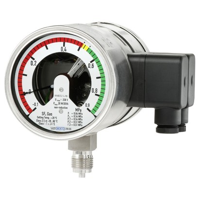
Hybrid gas density monitor
Description
Gas density is a crucial operating parameter for high-voltage plants. If the required gas density is not present, safe operation of the plant cannot be guaranteed.
The WIKA gas density measuring instruments provide reliable warnings against dangerously low gas levels, even under extreme ambient conditions. If the gas density drops as a result of a leakage, the switch contacts will switch. In addition to the traditional gas density monitor, with the model GDM-100-T high-precision sensors and evaluation electronics are incorporated.
Via the on-site display, the pressure based on 20 °C [68 °F] can be read directly on the instrument. With the integrated switch contacts, simple switching tasks can be realised quickly and without complication. The integrated 4 ... 20 mA or Modbus ® sensors integrated or attached to the instrument enable remote monitoring of the plant.
Left: Hybrid gas density monitor with integrated transmitter, model GDM-100-T
Right: Hybrid gas density monitor with attached transmitter, model GDM-100-T
The measured data for pressure, temperature and gas density are transmitted using the standardised Modbus ® RTU protocol. The model GDM-100-T can also be configured for alternative gases consisting of N₂, CF₄, O₂, CO₂, 3M™, Novec™ 4710, He and Ar.
The analogue version of the GDM-100-T uses the proven technology of the 4 ... 20 mA analogue signal and outputs the absolute pressure at 20 °C [68 °F] or the gas density in g/l for SF₆ gas as an analogue signal.
The data storage enables trend analysis to be carried out, so that critical SF6 gas conditions can be predicted and rectified in time. An optimisation of the maintenance strategy from time-based (TBM) to condition-based (CBM) is possible through the use of the gas density monitor.
Special features
- Ideally suited for smart grid or modernisation projects
- Modbus ® delivers measured values for pressure, temperature and gas density as digital signal
- The 4 ... 20 mA version outputs the absolute pressure at 20 °C [68 °F] or the gas density in g/l as an analogue signal for SF 6 gas
- Compact design with only one process connection
- Suitable for alternative gases
| Model | GDM-100-T |
| Product family | GDM |
| Subcategory | Hybrid gas density monitor with integrated/attached transmitter |
| Pressure ranges | 1.6…16 bar · 0…2.4 bar · 0…3.7 bar · 0…7.5 bar · 0…10.1 bar · 0…12.9 bar · 0…15.7 bar · 0…21.3 bar · 0…2 bar · 0…3 bar · 0…6 bar · 0…8 bar · 0…10 bar · 0…12 bar · 0…16 bar |
| Density reference temperature | 20 °C |
| Accuracy class | ±1 % at 20 °C, ±2.5 % from -20 ... +60 °C |
| Process connection | G 1/2 B per EN 837G 1/2 B |
| Output signal | 4 ... 20 mA · Modbus® RTU · Modbus RTU |
| Switching contacts | 3 |
| Wetted parts material | Stainless steel |
| Ambient temperature | −20…+60 °C |
| IP rating | IP65 |
| Weight | 1.4 kg |
| Certifications | RoHSCEEMC directive EN 61326EMC |
| Temperature compensation | Yes |
| Datasheet languages | EN |
| Option 1 | Laminated safety glass |
|---|---|
| Option 2 | Acrylic glass |
| Option 1 | 1 magnetic snap-action contact |
|---|---|
| Option 2 | 2 magnetic snap-action contacts |
| Option 3 | 3 magnetic snap-action contacts |
| Option 1 | Falling pressure |
|---|---|
| Option 2 | Rising pressure |
| Option 1 | Normally closed |
|---|---|
| Option 2 | Normally open |
View all (20)
| Option 1 | Galvanically connected |
|---|---|
| Option 2 | Galvanically isolated |
| Compensated pressure in bar abs. at 20 °C [68 °F] (g/l SF₆) | Pressure in bar abs. | Temperature | Output parameters | Output signal |
|---|---|---|---|---|
| 0 …2(12.28) | 0 …2.4 | -40 …+80 °C [-40 ...+176 °F] | ■ Density ■ Pressure at 20 °C [68 °F] ■ Pressure ■ Temperature | Modbus ® RTU |
| 0 …3(18.65) | 0 …3.7 | |||
| 0 ... 6 (38.87) | 0 ... 7.5 | |||
| 0 …8(53.4) | 0 …10.1 | |||
| 0 …10(68.96) | 0 …12.9 | |||
| 0 …12(85.79) | 0 …15.7 | |||
| 0 …16(124.64) | 0 …21.3 |
| Accuracy 1) | ||
|---|---|---|
| Compensated pressure ranges in bar abs. at 20 °C [68 °F] (g/l SF₆) 0 …2(12.28) 0 ... 6 (38.87) 0 …3(18.65) | For -40 ... -20 °C [-40 ... -4 °F] | ■ ±2 %(standard) ■ ±1.5 %(option) |
| Compensated pressure ranges in bar abs. at 20 °C [68 °F] (g/l SF₆) 0 …8(53.4) 0 …10(68.96) 0 …12(85.79) | For -20 ...+80 °C [-4 ...+176 °F] | ■ ±1.25 %(standard) ■ ±0.75 %(option) |
| 0 …16(124.64) | For -40 ...+80 °C [-40 ...+176 °F] | ■ ±1.25 %(standard) ■ ±0.6 %(option) |
| Pressure accuracy | ■ ±1 %at 20 °C [68 °F] (standard) ■ ±0.2 %at 20 °C [68 °F] (option) | |
| Temperature accuracy | ±1.5 K | |
| Reference conditions | Per IEC 61298-1 |
| Compensated pressure range in bar abs. at 20 °C [68 °F] (g/l SF₆) | Accuracy 1) | Output parameters | Output signal |
|---|---|---|---|
| 0 …2(12.28) | ■ ±2 %(standard) | Absolute pressure at 20 °C [68 °F] | 4 ...20mA |
| 0 …3(18.65) | ■ ±1.5 %(option) | ||
| 0 ... 6 (38.87) | |||
| 0 …8(53.4) | |||
| 0 …10(68.96) | |||
| 0 …12(85.79) | |||
| 0 …16(124.64) |
| Density range in g/l SF 6 (compensated pressure in bar abs. at 20 °C [68 °F]) | Accuracy 1) | Output parameters | Output signal |
|---|---|---|---|
| 0 …10(1.64) | ■ ±2 %(standard) ■ ±1.5 %(option) | SF₆ gas density in g/l | 4 ...20mA |
| 0 …16(2.59) | |||
| 0 ... 25 (3.97) | |||
| 0 …40(6.16) | |||
| 0 …60(8.87) | |||
| 0 …80(11.33) |
| Compensated pressure range in bar abs. at 20 °C [68 °F] (g/l SF₆) | Overload safety in bar abs. | Burst pressure in bar abs. |
|---|---|---|
| 0 ... 2 (12.28) | 6.2 | 10 |
| 0 ... 3 (18.65) | 14.5 | 24 |
| 0 ... 6 (38.87) | 14.5 | 24 |
| 0 ... 8 (53.4) | 31 | 52 |
| 0 ... 10 (68.96) | 31 | 52 |
| 0 ... 12 (85.79) | 31 | 52 |
| 0 ... 16 (124.64) | 62 | 103 |
| Case material | 316L |
|---|---|
| Case options | ■ Cable outlet ■ Metal cable outlet, shield optionally connected (heavy-duty version) |
| Voltage supply | DC10…30V |
|---|---|
| Power consumption | |
| Model GD-20-A | ≤ 0.75W |
| Model GD-20-D | ≤ 0.45W |
| Maximum permissible load R A (model GD-20-A) | R A ≤ (U B - 9.5 V) / 0.023 A with R A in ohm and U B inV |
| Time response | |
| Settling time 1) | < 10 ms |
| Switch-on time 2) | ≤ 500 ms |
| 1 | - | - |
|---|---|---|
| 2 | U + | DC 10 ...30V |
| 3 | U - | Mass |
| 4 | A | RS-485 signal |
| 5 | B | RS-485 signal |
| 6 | - | - |
| 1 | U + | DC 10 ...30V |
|---|---|---|
| 2 | - | - |
| 3 | U - | Mass |
| 4 | - | - |
| 5 | - | - |
| 6 | - | - |
| Electrical safety | |
|---|---|
| Model GD-20-D | Reverse polarity voltage U + vs.U - |
| Model GD-20-A | Reverse polarity voltage U + vs.U - |
| Immunity to EMF | 30 V/m (at 80 MHz to 6 GHz) |
|---|---|
| Immunity against surge voltages (surge) per IEC 61000-4-5 | 1 kV, non-symmetrical, cables to ground, RS485A to RS485B, U + vs.U - |
| ESD per IEC 61000-4-2 | 8 kV contact discharge, 15 kV indirect discharge, 8 kV indirect discharge |
| Immunity against conducted HF signals in accordance with IEC 61000-4-6 | 10V at 150 kHz to 80 MHz |
| Immunity against fast transients (burst) per IEC 61000-4-4 | 4 kV |
| Logo | Description | Country |
|---|---|---|
| EU declaration of conformity | European Union |
| Designation | Case ingress protection | Temperature range in | °C Shield provided customer | Shield connected on the instrument | Assignment | |
|---|---|---|---|---|---|---|
| side | U + | U - | ||||
| Cable outlet 2 m, plastic | IP67 | -40 ...+80 °C [-40 ...+176 °F] | Yes | - | Brown | Blue |
| Cable outlet 5 m, plastic | Yes | - | ||||
| Cable outlet 10 m, plastic | Yes | - | ||||
| Cable outlet 2 m, SS | Yes | - | ||||
| Cable outlet 5 m, SS | Yes | - | ||||
| Cable outlet 10 m, SS | Yes | - | ||||
| Cable outlet 2 m, shield connected, SS | Yes | Yes | ||||
| Cable outlet 5 m, shield connected, SS | Yes | Yes | ||||
| Cable outlet 10 m, shield connected, SS | Yes | Yes |
| Model | Description | Order number |
|---|---|---|
| Modbus ® start-up kit | ■ Power supply unit for sensor ■ Connection cable ■ Interface converter (RS-485 to USB) ■ USB cable type A to type B ■ Modbus ® tool software on USB stick | 14075896 |
| WIKAsoft-GD for configuration and testing of the digital sensor | Free download from: www.wika.com/download | - |
| Optional accessories | ||
| Recalibration valve | Model GLTC-CV ■ Enables easy recalibration of the gas density monitor without dismounting ■ Welded permanently to the instrument or available as loose valve for retrofitting | - |
| Connection cable for Switching outputs | ■ Terminal without wiring ■ Connector mounted on the instrument side, cable with loose ends | - |
| Description | Order number |
|---|---|
| Adapter from test connection (M26 x 1.5) to quick coupling | 14146937 |
| Protective cap for test connection (M26 x 1.5) | 14193772 |
| Calibration system for SF₆ gas density measuring instruments, model BCS-10 | SeeWIKA data sheet SP 60.08 |
| Calibration system for SF₆ gas density measuring instruments, model ACS-10 | SeeWIKA data sheet SP 60.15 |
Couldn't find the answer in the documentation? An engineer will reply within a business day.
Ask an engineer →