
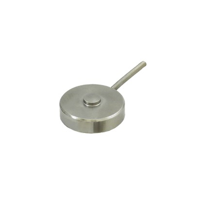
Compression force transducer with strain gauges
Description
The model F1226 compression force transducer in miniature design with strain gauges is suitable for both static and dynamic force measurement in the direct force flow.
The spherical cap with spherical surface, also known as load introduction button, serves to absorb compression forces and ensures axial, perpendicular and centred force introduction. The force is thus transmitted centrally and evenly into the instrument. This enables precise measurement of the actual compression forces in a wide variety of applications.
The measuring spring is elastically deformed by a compression force introduced in the force direction. The resulting mechanical tensions are measured by the strain gauges, converted into an electrical output signal and output as an mV/V signal.
Special features
- Rated forces from 0 ... 5 lb to 0 ... 50,000 lb [0 ... 22.24 N to 0 ... 222.41 kN]
- For static and dynamic measurement
- Force introduction via the spherical cap
- Compression calibration
- Compact miniature design, low installation height
| Model | F1226 |
| Subcategory | Compression force transducer |
| Force ranges | 0…5 lb · 0…50000 lb · 0…22.24 N · 0…222.41 kN · 0…2.268 kg · 0…22680 kg · 5…50000 lb · 2.268…22680 kg · 22.24…222.41 kN · 22.24…444.82 N |
| Accuracy class | ±0.25 % Fnom |
| Process temperature | −54…+121 °C |
| Mounting type | Compression |
| Output signal | 2 mV/V |
| Cell material | Stainless steel |
| Ambient temperature | −54…+121 °C |
| IP rating | IP67 |
| Weight | 0.454 kg |
| Certifications | EACRoHSEU declaration of conformity |
| Overload protection | 150 % |
| Cable length | 1.5 m |
| Datasheet languages | EN |
| Standard | In accordance with directive VDI/VDE/DKD 2638 |
|---|---|
| Material of the measuring body | Stainless steel |
| Ingress protection (per DIN IEC/EN 60529) | IP67 |
| Weight | Approx. 1 lb [approx. 453.5 g] |
| Type of measuring element | Strain gauges |
|---|---|
| Range of use | For static and dynamic measurement |
| Input resistance R e | 350Ω |
| Output resistance R a | 350Ω |
| Rated displacement s nom | < 0.004 in [ < 0.1mm ] |
| Force introduction | Compression force on spherical cap |
| Relative linearity error d lin | ±0.25%F nom |
|---|---|
| Relative reversibility error v | ±0.15%F nom |
| Relative repeatability error in unchanged mounting position b rg | ±1%F nom |
| Relative deviation of zero signal d S, 0 | ±2%F nom |
| Temperature effect on zero signal TC 0 | ≤ ±0.09 %/ 10 K |
| Temperature effect on characteristic value TC C | ≤ ±0.18 %/ 10 K |
| lb | |
|---|---|
| 5 | 3,000 |
| 10 | 5,000 |
| 50 | 7,500 |
| 100 | 15,000 |
| 250 | 20,000 |
| 1,000 | 30,000 |
| 2,000 | 50,000 |
View all (12)
| kg | |
|---|---|
| 2.268 | 1,361 |
| 4.536 | 2,268 |
| 22.68 | 3,402 |
| 45.36 | 6,804 |
| 113.4 | 9,073 |
| 453.59 | 13,608 |
| 907 | 22,680 |
| Force limit F L | 150%F nom |
|---|---|
| Breaking force F B | > 300%F nom |
| Vibration stress F rb per DIN 50100 | 70%F nom |
| 0.0222 [22.24 N] | 13.35 |
|---|---|
| 0.0445 [44.48 N] | 22.24 |
| 0.222 [222.41 N] | 33.36 |
| 0.445 [444.82 N] | 66.72 |
| 1.112 | 88.96 |
| 4.448 | 133.45 |
| 8.896 | 222.41 |
| Rated temperature range B T, nom | --65 ...+250 °F [-54 …+121 °C] |
|---|---|
| → Other rated temperature ranges on request | |
| Compensated rated temperature range | 59 ... 159,8 °F [15 …71°C] |
| Operating temperature range B T, G | -65 ...+250 °F [-54 ...+121 °C] |
| Reference temperature T ref | 73 °F [23 °C] |
| Storage temperature range | -65 ...+250 °F [-54 ...+121 °C] |
| Humidity | 35 ... 85 %relative humidity |
| Condensation | Non-condensing |
| Operating altitude | ≤ 8,202 ft [2,500 m] above sea level |
| Packaging | Individual packaging |
|---|---|
| Instrument labelling (product label) | → See operating instructions 14505085 |
| Logo | Description | Region |
|---|---|---|
| EU declaration of conformity | European Union | |
| EAC RoHS directive | Eurasian Economic Com- munity |
| Rated load/force F nom | Dimensions in inch | ||||||||
|---|---|---|---|---|---|---|---|---|---|
| lb | kg | kN/N | ØA | B | C | ØD | E | F | ØG |
| 5 ... 100 | 2.268 ... 45.36 | 22.24 N ... 444.82 N | 0.21 | 0.62 | 0.05 | 1.00 | 4-40 UNC | 0.22 | 0.750 |
| 250 ... 2,000 | 113.4 ... 907 | 1.112 ... 8.896 kN | 0.32 | 0.39 | 0.07 | 1.25 | 6-32 UNC | 0.19 | 1.000 |
| 3,000 ... 5,000 | 1,361 ... 2,268 | 13.35 ... 22.24 kN | 0.43 | 0.63 | 0.08 | 1.50 | 6-32 UNC | 0.25 | 1.250 |
| 7,500 ... 15,000 | 3,402 ... 6,804 | 33.36 ... 66.72 kN | 0.43 | 0.63 | 0.08 | 1.75 | 6-32 UNC | 0.25 | 1.500 |
| 20,000 ... 30,000 | 9,0723 ... 13,608 | 88.96 ... 133.45 kN | 0.60 | 1.00 | 0.12 | 2.00 | 6-32 UNC | 0.25 | 1.625 |
| 50,000 | 22,680 | 222.41 kN | 0.78 | 1.50 | 0.18 | 3.00 | 6-32 UNC | 0.25 | 2.375 |
| Rated load/force F nom | Dimensions inmm | ||||||||
|---|---|---|---|---|---|---|---|---|---|
| lb | kg | kN/N | ØA | B | C | ØD | E | F | ØG |
| 5 ... 100 | 2.268 ... 45.36 | 22.24 N ... 444.82 N | 5.33 | 15.75 | 1.27 | 25.40 | M4 | 5.59 | 19.05 |
| 250 ... 2,000 | 113.4 ... 907 | 1.112 ... 8.896 kN | 8.13 | 9.91 | 1.78 | 31.75 | M4 | 4.83 | 25.40 |
| 3,000 ... 5,000 | 1,361 ... 2,268 | 13.35 ... 22.24 kN | 10.92 | 16.00 | 2.03 | 38.10 | M4 | 6.35 | 31.75 |
| 7,500 ... 15,000 | 3,402 ... 6,804 | 33.36 ... 66.72 kN | 10.92 | 16.00 | 2.03 | 44.45 | M4 | 6.35 | 38.10 |
| 20,000 ... 30,000 | 9,0723 ... 13,608 | 88.96 ... 133.45 kN | 15.24 | 25.40 | 3.05 | 50.80 | M4 | 6.35 | 41.275 |
| 50,000 | 22,680 | 222.41 kN | 19.81 | 38.10 | 4.57 | 76.20 | M4 | 6.35 | 60.325 |
Couldn't find the answer in the documentation? An engineer will reply within a business day.
Ask an engineer →