
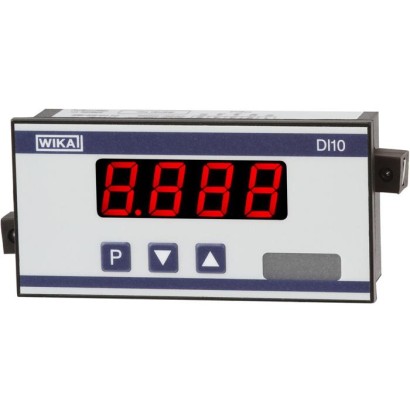
Digital indicator for panel mounting
Description
The DI10 digital indicator, with its small mounting depth, is ideally suited for mounting in applications with limited mounting space. As a result of this small insertion depth, it can be used in applications where other indicators would be too large.
The digital indicator is suitable for industry-standard 4 ... 20 mA current loop signals. The power supply for the display comes directly from the current loop, so no additional power supply is needed.
The display is parameterised through a logically-structured menu which enables intuitive operation. The settings can be made using the control keys on the front.
The parameterisation enables the setting of the indication range and an offset. In addition, a sensor signal can be
Digital indicator model DI10
Fig. top: for panel mounting
Fig. bottom: for wall mounting
linearised with up to 10 programmable points. The display time can be varied between 0.1 and 10 seconds. In order to prevent unintentional changes by the operator within the menu system, a programming lock can be activated.
The retrieval of the Min/Max values is made through the simple operation of the control keys.
Two PhotoMOS outputs are available as options, with adjustable hysteresis independent of each other.
For convenient installation outside of electrical panels, the display is also available in a practical wall-mount enclosure, which offers an ingress protection of IP 65.
Special features
- Suitable for 4 ... 20 mA current loops
- Min/Max value memory
- Linearisation with up to 10 programmable points
- 2 optional potential-free switch contacts
- Minimal mounting depth: 25 mm without plug-in terminal
| Model | DI10 |
| Product family | DI |
| Subcategory | Digital indicator |
| Accuracy class | ±0.3 % of the measuring span ±1 digit |
| Accuracy standard | EN 61326, EN 61010 |
| Output signal | 4-20 mA |
| Power supply | Powered from 4-20 mA loop |
| Electrical connection | 5-pin terminal block, screw terminals up to 2.5 mm² |
| Switching function | Adjustable hysteresis, galvanically isolated |
| Switching contacts | 2 |
| Case material | PC polycarbonate, black, ASA, black, PG gland |
| Ambient temperature | +0…+60 °C |
| IP rating | IP65/IP00 |
| Weight | 0.05 kg |
| Certifications | CE |
| Datasheet languages | EN |
| Display | |
|---|---|
| Principle | 7-segment LED, red, 4-digit |
| Character size | 14mm |
| Indication range | -1999 ... 9999 |
| Display rate | 0.1 ... 10 sec |
| Memory | Flash memory (independent of power supply), data retention > 100 years |
| Input | |
| Number and type | 1 x 4 ... 20 mAcurrent input |
| Accuracy | ±0.3 %of the measuring span ±1 digit |
| Measuring time | 0.1 ... 10.0 sec |
| Voltage drop | approx.DC 5.1 V, max.150mW {approx.DC 8.0V for the option with two switching outputs, max. 200 mW} |
| Power supply | Not required, since the digital indicator is powered from the 4 ... 20 mAloop |
| Electrical connection | screw terminals, conductor cross-section up to 2.5 mm² |
| {Switching output} | |
| Number and type | 2 PhotoMOS outputs, galvanically isolated max.AC/DC 30 V, max. 0.4 A |
| Material | PC polycarbonate, black |
|---|---|
| Ingress protection | Front: IP 65; Rear: IP 00 |
| Dimensions | 96 x 48 x 41 mm(WxHxD)including screw terminals |
| Weight | approx. 50 g |
| Mounting | Screw elements for wall thicknesses up to3mm |
| {Wall-mount enclosure} | |
| Material | ASA, black, PG gland |
| Ingress protection | IP 65 |
| Dimensions | 160x90x60mm(WxHxD) |
| Weight | approx. 300 g |
| Mounting | Fixing holes for screws |
| Operating temperature | 0 ... 60 °C |
|---|---|
| Storage temperature | -20 ...+80 °C |
| Relative humidity | 0 ... 80 %mean annual relative humidity, non-condensing |
| EMCdirective | 2004/108/EC, EN 61326 emission (group 1, class B) and interference immunity (industrial application) |
|---|---|
| Safety regulations | EN 61010 |
View all (6)
| Model | Panel-mount unit | Wall-mount unit |
|---|---|---|
| Without switching outputs | 14019785 | 14024082 |
| With 2 switching outputs | 14019786 | 14024084 |
| 1 | IB | internal bridge within instrument |
|---|---|---|
| 2 | + I rel | Measuring signal current input (only in conjunction with switch outputs) |
| 3 | + I in | Current measuring signal |
| 4 | - I in | Current measuring signal |
| 5 | IB | internal bridge within instrument |
Couldn't find the answer in the documentation? An engineer will reply within a business day.
Ask an engineer →4 standard articles of family DI
If you know the code — pick directly. If not — use the configurator in mode “01”.