
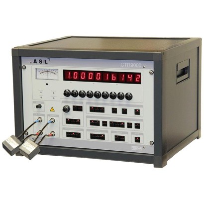
Primary-standard resistance thermometry bridge
Description
In metrology, the most important consideration is the quality of the fundamental measurement. The bridge technology from ASL represents the peak of performance in resistance thermometer measurement. It exploits the inherent advantages of AC bridge technology to maintain repeatable measurements of highest precision under practical operating conditions.
The model CTR9000 primary-standard resistance thermometry bridge is designed specifically for resistance thermometry to provide the best possible accuracy.
Model CTR9000 primary-standard resistance thermometry bridge, version 20 ppb accuracy
The 25/30 2) Hz or 75/90 2) Hz operating frequency provides fast, continuous measurement with high immunity to thermal EMF errors and supply frequency noise sources.
Practical measurements involve cables, connectors and imperfect operating environments. The CTR9000 achieves its full specification under a wide range of real operating conditions.
AC bridge technology will always outperform measurements made using DC technology with slow current reversal. These benefits are inherent to the fundamentals of electrical measurement and not just the implementation.
2) 60 Hz supply frequency Page 1 of 7
Special features
- Accuracy: < ±20 ppb [±5 μK], optional < ±0.1 ppm [±25 μK] (25 Ω SPRT referred to a 25 Ω reference resistor)
- Resolution: 1 ppb [0.25 μK], optional 0.1 ppm [25 μK] (25 Ω SPRT referred to a 25 Ω reference resistor)
- Fast measurement time (2 seconds balance)
- Differential and absolute measurement
- Warm-up time < 30 seconds
| Model | CTR9000 |
| Product family | CTR |
| Subcategory | Resistance thermometry bridge |
| Temperature ranges | −189…+660 °C |
| Uncertainty | < ±20 ppb (±5 μK) or optional < ±0.1 ppm (±25 μK) |
| Calibration type | temperature_bath |
| Output signal | DC +10 V · DC -10 ... +10 V · DC +10 V max · DC -10 ... +10 V max |
| Ambient temperature | +15…+25 °C |
| Weight | 46 kg |
| Certifications | CE |
| Portable | No |
| Datasheet languages | EN |
| Specifications | Model CTR9000 |
|---|---|
| Input channels | 2 on the main device (one platinum resistance thermometer (PRT) or standard platinum resistance thermometer (SPRT) or resistor + one reference resistor) 60; over multiplexer CTS9000 |
| Input connections | 4 x BNC + shield (front panel) |
| Data entry format | ITS 90 and CVD for calibrated probes; or EN 60751 for uncalibrated probes |
| Accuracy 1) | 0.1 ppm ratio error over full range or 20 ppb ratio error over full range, dependent on configuration |
| Measuring ranges | |
| Sense current | 1 mA, 2 mA,5mA |
| Sense current mulitpliers | 0.1, 10 and √2 |
| Sense current accuracy | Accuracy option 0.1 ppm:±1% Accuracy option 20 ppb:±0.1% |
| Carrier frequency | 50 Hz supply frequency: low 25 Hz, high 75 Hz 60 Hz supply frequency: low 30 Hz, high 90 Hz Phase locked to the local supply frequency |
| Bandwidth | Accuracy option 0.1 ppm: 0.5 Hz, 0.1 Hz, 0.02 Hz Accuracy option 20 ppb: 0.5 Hz, 0.2 Hz, 0.1 Hz, multiplier x 0.1, x 0.01 |
| Measuring range | 0 ...260Ω |
| Rated accuracy range | 0 ...130Ω |
| Rs range | 1 ...200Ω |
| Display | |
| Range | Accuracy option 0.1 ppm: 1.299 999 9 ratio of two resistors Accuracy option 20 ppb: 1.299 999 999 ratio of two resistors |
| Resolution | The digital resolution is typically 0.01 ppm with a Pt100 at 1 mA. |
| Voltage supply | |
| Power supply | AC 240 V, AC 220V AC 120 V, AC 100V User selectable on rear panel |
| Supply frequency | 50 or 60 Hz |
| Power consumption | max.250VA |
| Permissible ambient conditions | |
| Operating temperature | 15 ... 25 °C |
| Communication | |
| Interface CTR9000 | IEEE-488.2 |
| Interface via driver module CTS9000 (optional) | RS-232 or IEEE-488.2 |
| Case | |
| Dimensions | Approx. 545 x 382 x 500mm(WxHxD) |
| Weight | 46 kg |
| Model | Dimensions | Temperature range | Detector length |
|---|---|---|---|
| CTP5000-T25 | Pt25, d = 6.5 ... 7.5 mm, l = 480mm | -189 ...+660 °C | 45mm |
| Parameter | Parameter selection |
|---|---|
| SOURCE IMPEDANCE | |
| 1, 10, 100 | Select to match the bridge pre-amp input impedance to the source impedance for optimum noise performance.The source impedance depends on the standard resistor, SPRT resistance and lead resistance. Default setting is 100 . |
| FREQUENCY | |
| Low, High | Set as required.Make measurements at both frequencies if AC effects are to be evaluated.The normal setting is High . |
| GAIN (switched) | |
| x1, x10, x10² x10³, x10 4 | Set gain to achieve required resolution in manual or automatic modes. 10 4 gives resolution of 0.1 ppm 10³ gives resolution of 1 ppm etc. The normal setting is 10 4 (accuracy 0.1 ppm) and 10 5 (accuracy 20 ppb). |
| Sensitivity | For normal manual or automatic modes set to x5.0 (0.1 ppm), x3.2 (20 ppb). Make fine adjustments to optimise balancing in Auto mode. |
| REFERENCE AMP / QUAD GAIN | |
| x1, x10², x10 4 | Set to a minimum which does not result in saturation of the quad servo. Check that the reference amplifier is not saturated. Normal setting x10 . |
| CARRIER | |
| Current | Select maximum carrier current that does not exceed the ratio transformer saturation limits or cause excessive self-heating of the PRT. Refer to the PRT manufacturer's instructions.Check self-heating with x√2 facility. Default setting is 1 mA . |
| CHECK | |
| Zero, Unity | The bridge operation can be verified by performing a zero and unity check. Suitable resistors should be connected to Rt and Rs with appropriate bridge settings. Default setting is normal operation. |
| METER | |
| In-Phase, Quad, Residual | Use front panel meter to measure the amount of in-phase, quadrature and residual signals coming through the detector. Default setting is In-Phase . (Both LEDs off.) |
| BANDWIDTH (Hz) | |
| 0.5, 0.1, 0.02 (option 0.1 ppm) 0.5, 0.1, 0.2 x0.1/x0.01 (option 20 ppb) | Set to the maximum bandwidth to achieve the required resolution in automatic balance mode.This does not affect manual operation. |
Couldn't find the answer in the documentation? An engineer will reply within a business day.
Ask an engineer →